Imagine a company where two teams, Sales and Technical, share the same network. Both are connected to the same switch, and their traffic flows together without any separation. All network traffic moves freely between every device, with no boundaries or restrictions. At first, it feels simple and convenient, one big network for everyone.
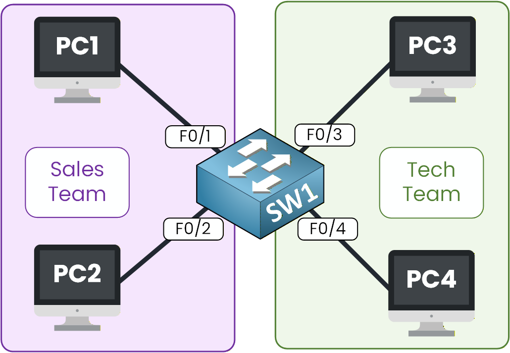
Figure 1 - The switch connected to the sales and tech teams
The Need for VLANs
But under the surface, this setup is far from ideal. When one PC sends an ARP request, the switch forwards it to every other connected device, even those that don't need it. As the number of devices grows, the network becomes noisier, slower, and harder to manage.
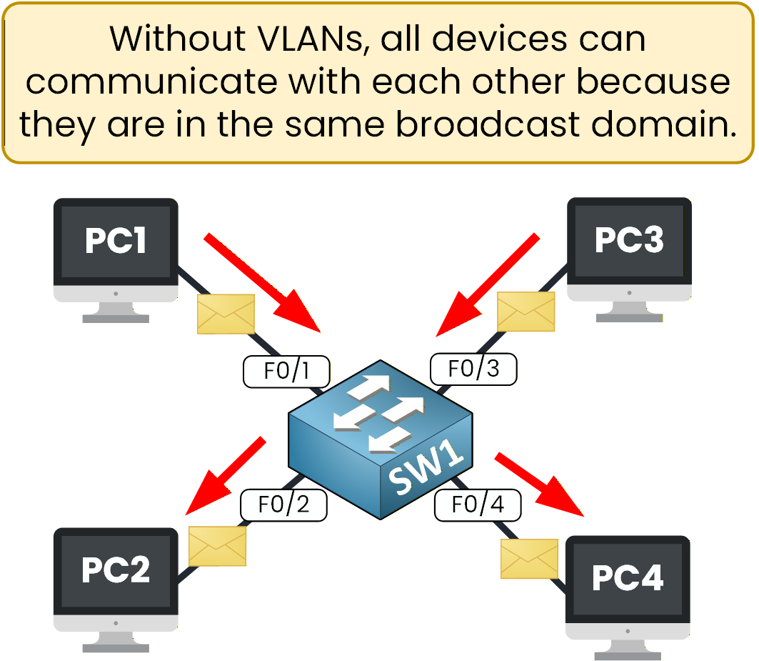
Figure 2 – Default switch behavior: all devices can communicate freelySecurity and Efficiency Risks
There's also a security concern. Sales and Technical users share the same broadcast domain, meaning they can potentially capture each other's traffic. Sensitive data, internal files, or credentials might circulate across the same network without restriction. In short, everyone is “in the same room,” and anyone can overhear the conversation.
This situation is neither secure nor practical.
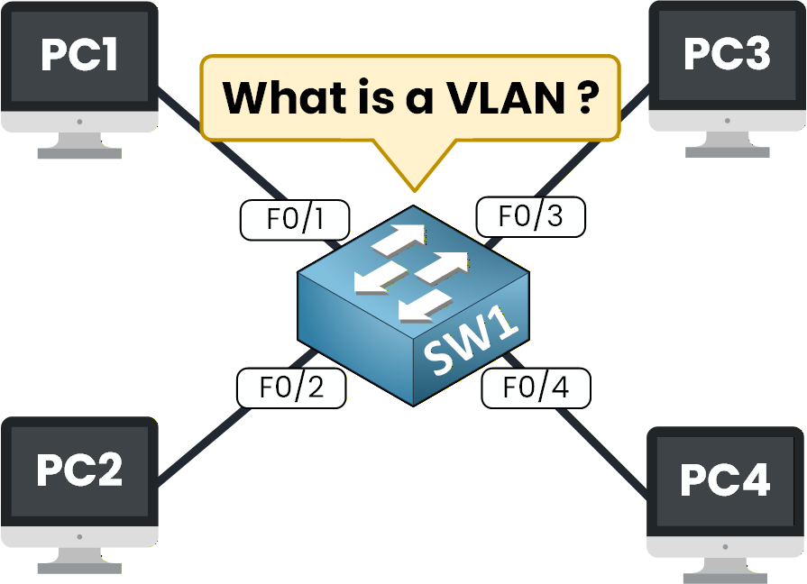
Figure 3 – Illustration of a switch connecting many PCs to explain VLAN concepts.
Why VLANs Were Created
To solve this, network engineers created VLANs — Virtual Local Area Networks.
A VLAN divides a single switch into multiple logical networks, each acting as an independent network.
You can think of it as building walls inside the same building: Sales and Technical teams still share the same switch, but they now work in separate rooms.Each VLAN forms its own broadcast domain, keeping traffic isolated and organized.
This improves performance, strengthens security, and gives administrators more control over how devices communicate.This simple concept completely changes how switches operate. It's one of the most fundamental principles in network design and a core topic in the CCNA. Before diving deeper, let's see what actually happens when a switch operates without VLANs configured.
Answer the question below
Let's look at how a switch behaves before VLANs are configured. A typical Layer 2 switch, such as a Cisco switch, forwards frames based on MAC addresses. It learns which MAC address is associated with each port and uses that information to deliver traffic efficiently within the same network.
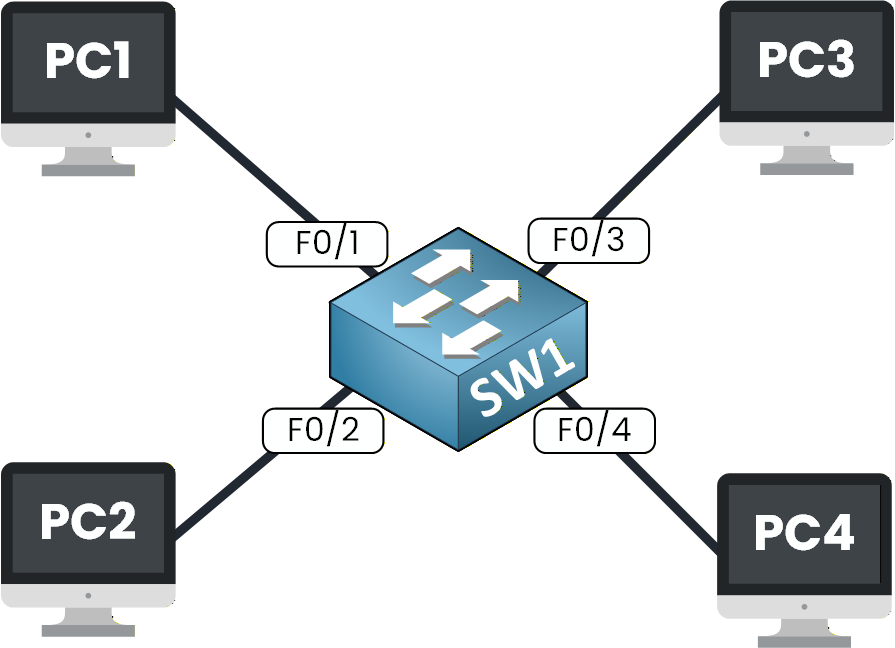
Figure 4 – A basic VLAN diagram showing four PCs connected to a single switch
In this setup, several devices — PC1, PC2, PC3, and PC4 — are connected to the same switch. By default, all switch ports belong to VLAN 1, which means the entire switch operates as a single network.
All devices appear to be on the default VLAN, VLAN 1, as shown in Figure 5.
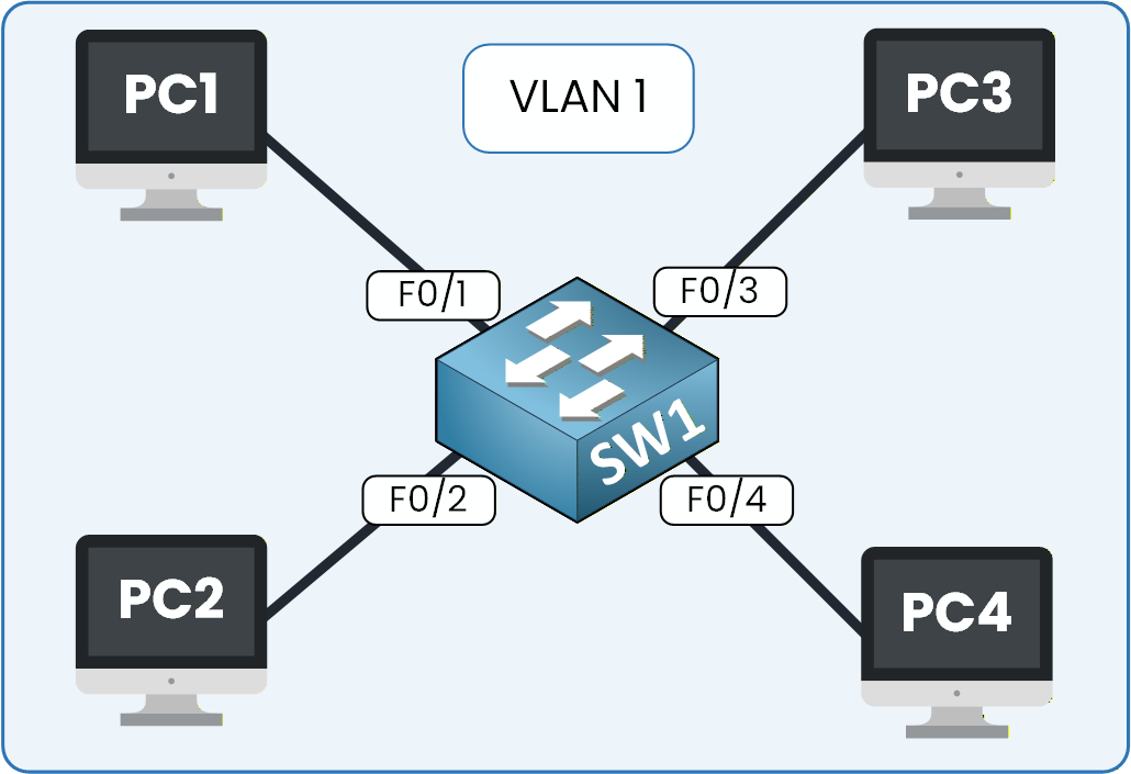
Figure 5 – Default switch behavior with all ports in VLAN 1
You can verify this behavior using the Cisco CLI by applying the commands provided in the instructions.
SW1> enable
SW1# show vlan brief
VLAN Name                             Status    Ports
---- -------------------------------- --------- -------------------------------
1    default                          active    Fa0/1, Fa0/2, Fa0/3, Fa0/4
                                                Fa0/5, Fa0/6, Fa0/7, Fa0/8
                                                Fa0/9, Fa0/10, Fa0/11, Fa0/12
                                                Fa0/13, Fa0/14, Fa0/15, Fa0/16
                                                Fa0/17, Fa0/18, Fa0/19, Fa0/20
                                                Fa0/21, Fa0/22, Fa0/23, Fa0/24
                                                Gig0/1, Gig0/2
1002 fddi-default                     active
1003 token-ring-default               active
1004 fddinet-default                  active
1005 trnet-default                    active
The output confirms that all switch ports are assigned to VLAN 1.
40 % Complete: you’re making great progress
Ready to pass your CCNA exam?