Imagine you’ve just joined a mid-sized company as the new network administrator.
Your first task involves VLAN configuration to place the Sales and Tech teams into separate broadcast domains.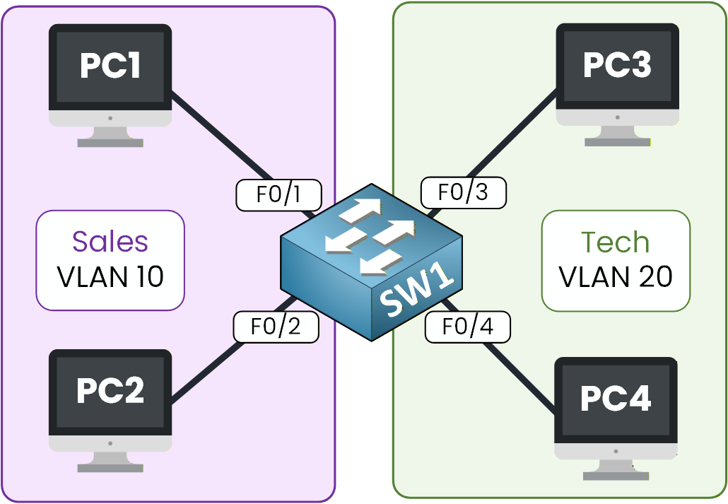
Figure 1 – Topology used to configure VLANs
Your goal in this lab is to fix that by creating:
VLAN 10 for Sales
VLAN 20 for Tech
Let’s get started!
How to Begin
Download the lab file at the top of the page and open it in Packet Tracer.
The topology is ready and waiting for you; we will only focus on the VLAN configuration.Lab Overview
Here’s the structure we’ll follow throughout this lab:
Step 1 – Create the VLANs
Step 2 – Place Devices in Their VLANs
Step 3 – Test Your VLAN Segmentation
Step 4 – Maintain and Reset VLANs
Let’s Get Started
Open the Packet Tracer file and follow each step with me.
You don’t need to know the commands yet, we’ll learn them together, and you’ll apply them directly in Packet Tracer as we progress.Let’s go!
Answer the question below
Let’s now move from theory to practice.
In this first step, your goal is to create the two VLANs we will use throughout the lab:VLAN 10 for the Sales team
VLAN 20 for the Tech team
Each VLAN will act as a separate broadcast domain.
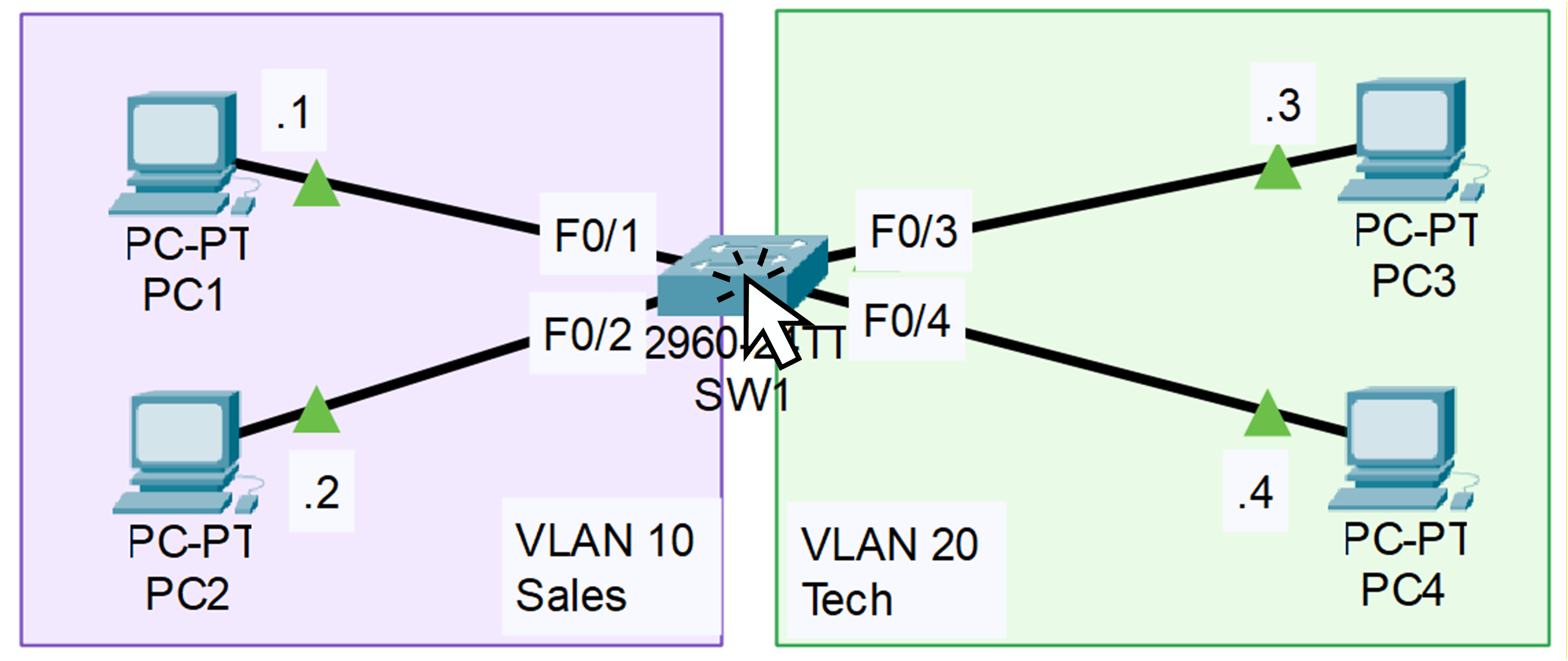
Figure 2 – VLAN Topology on Packet Tracer
Before we start creating anything, click on SW1 in Packet Tracer so we can look at its current VLAN configuration.
Check Existing VLANs
To see all VLANs configured on the switch, enter the following command:
SW1# show vlan brief

VLAN Name                             Status    Ports
---- -------------------------------- --------- -------------------------------
1    default                          active    Fa0/1, Fa0/2, Fa0/3, Fa0/4
                                                Fa0/5, Fa0/6, Fa0/7, Fa0/8
                                                Fa0/9, Fa0/10, Fa0/11, Fa0/12
                                                Fa0/13, Fa0/14, Fa0/15, Fa0/16
                                                Fa0/17, Fa0/18, Fa0/19, Fa0/20
                                                Fa0/21, Fa0/22, Fa0/23, Fa0/24
                                                Gig0/1, Gig0/2
1002 fddi-default                     active
1003 token-ring-default               active
1004 fddinet-default                  active
1005 trnet-default                    active
As you can see, the switch currently has VLAN 1, which is the default VLAN, and all interfaces are assigned to it.
You can also see VLANs 1002 to 1005. These VLANs are created automatically on Cisco switches and correspond to very old technologies.
We don’t need them for this lab, so you can safely ignore them.Right now, everything is in VLAN 1, meaning Sales and Tech traffic is mixed together.
Let’s change that by creating the two VLANs we need.Entering Configuration Mode
To create the VLANs, we first need to enter global configuration mode.
This mode allows you to modify the switch’s behavior, including VLANs, interfaces, and many other features.SW1# configure terminalThis command moves you out of
user EXEC modeand into the configuration environment, where you can start applying changes to the switch.Create VLAN 10 (Sales)
Let’s begin by creating the first VLAN for the Sales team.
SW1(config)# vlan 10
SW1(config-vlan)# name ?
  WORD  The ascii name for the VLAN

SW1(config-vlan)# name Sales
SW1(config-vlan)# exit
You’ve now added VLAN 10 to the switch’s VLAN database.
At this moment, it exists on the switch, but no interfaces are assigned to it yet, so it doesn’t impact traffic.Create VLAN 20 (Tech)
Now repeat the same process for the Tech department:
SW1(config)# vlan 20
SW1(config-vlan)# name Tech
SW1(config-vlan)# exit
Just like VLAN 10, VLAN 20 is now created inside the switch’s VLAN database.
However, since no ports belong to it yet, nothing has changed on the network.Verifying VLAN Creation
Before we continue, let’s make sure both VLANs were successfully created.
Use the command below to display all VLANs on the switch:SW1# show vlan brief VLAN Name Status Ports ---- -------------------------------- --------- ------------------------------- 1 default active Fa0/1, Fa0/2, Fa0/3, Fa0/4 Fa0/5, Fa0/6, Fa0/7, Fa0/8 Fa0/9, Fa0/10, Fa0/11, Fa0/12 Fa0/13, Fa0/14, Fa0/15, Fa0/16 Fa0/17, Fa0/18, Fa0/19, Fa0/20 Fa0/21, Fa0/22, Fa0/23, Fa0/24 Gig0/1, Gig0/2 10 Sales active 20 Tech active 1002 fddi-default active 1003 token-ring-default active 1004 fddinet-default active 1005 trnet-default activeUnderstanding the Output
You can now see that VLAN 10 and VLAN 20 both exist on the switch.
However, all switchports are still assigned to VLAN 1, which is the default VLAN for every interface.This means that, for the moment, traffic from Sales and Tech is still mixed together.
There is no separation between the two groups yet, and that’s expected, VLANs only become effective once you assign interfaces to them.Quick Recap
So far, you’ve learned how to:
Enter configuration mode on a Cisco switch
Create VLANs and name them properly
Verify their presence using
show vlan brief
In the next section, we’ll assign specific switch ports to each VLAN so that the Sales and Tech devices become properly separated into their own broadcast domains.
Answer the question below
How many VLANs did you create?
Now that your VLANs exist in the switch’s VLAN database, it’s time to assign the correct interfaces to each VLAN.
This is the moment where the logical separation becomes real: by mapping physical ports to specific VLANs, you ensure that the Sales and Tech teams no longer share the same broadcast domain.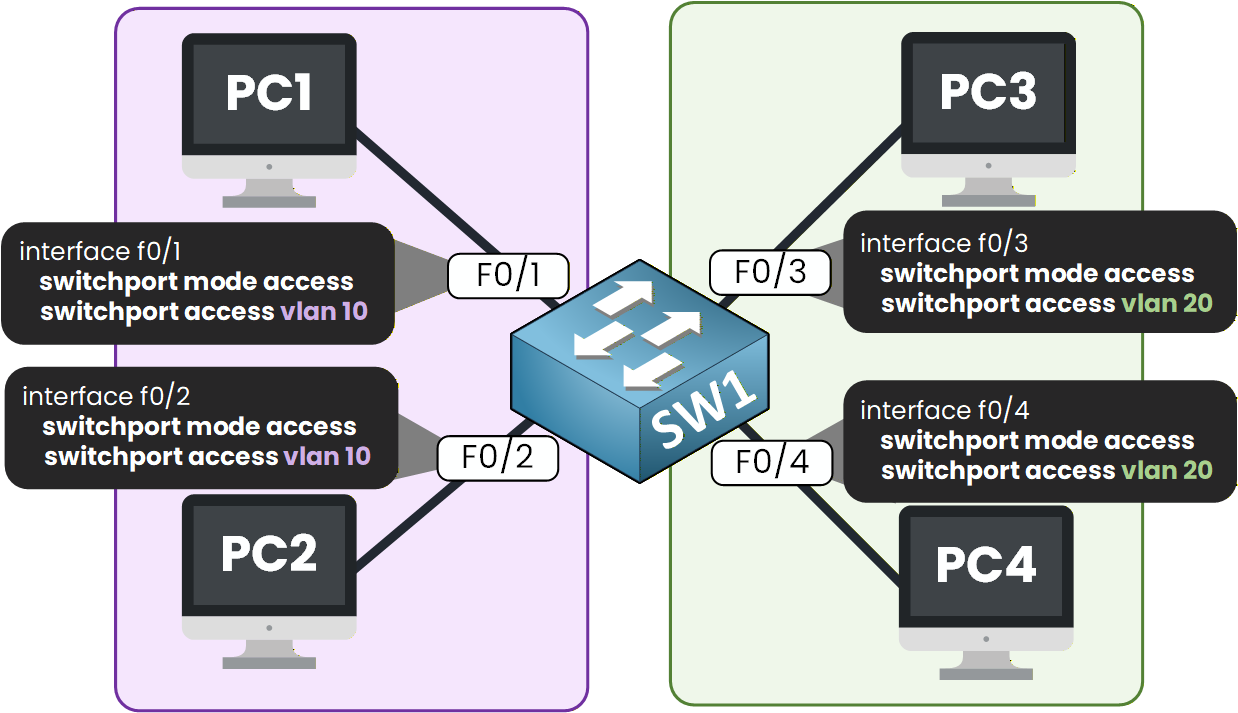
Figure 3 – Access Port Configuration per VLAN
To do this, you’ll use two key commands:
switchport mode accessswitchport access vlan X
Let’s apply them step by step.
40 % Complete: you’re making great progress
Unlock the rest of this lesson
If you’d like to continue your CCNA journey, simply create your free account.
Access all CCNA lessons
Practice with hands-on labs
Train with Practice exams and Quizzes
Progress tracking in your dashboard
Made by network engineers - CCNP certified
learners globally