Imagine a company that wants to double its bandwidth and ensure redundancy between switches but without causing loops. That’s exactly what EtherChannel does: it combines multiple physical links into a single logical one.

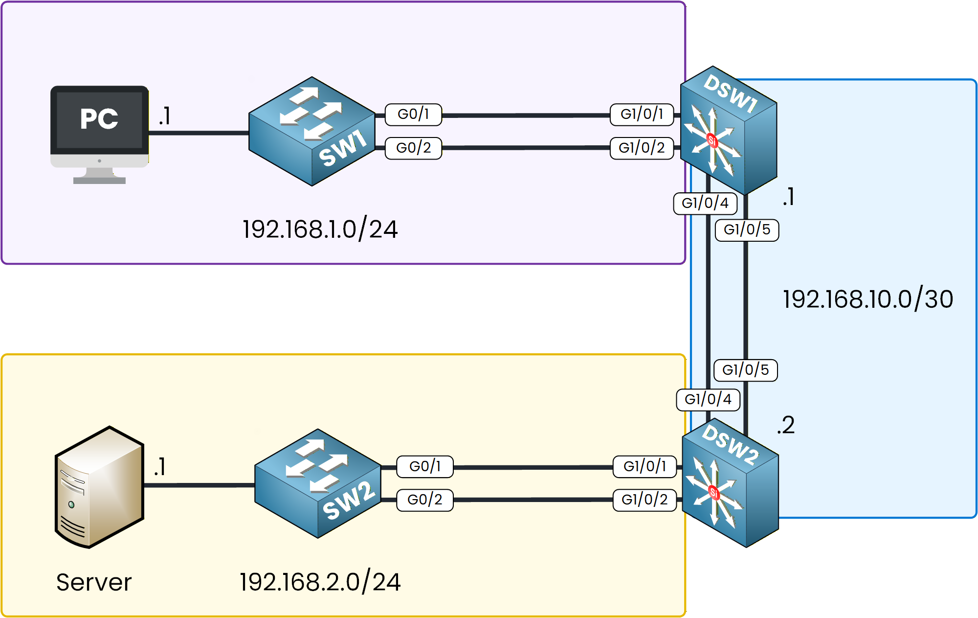
Figure 1 - EtherChannel Configuration Topology
So far in this course, we’ve seen how EtherChannel can be configured using different methods:
In this lab, you’ll put all of that into practice.
We’ll recap everything step by step, so you can configure and verify each EtherChannel type directly in Packet Tracer.How to Begin
Before starting, download the lab file using the button at the top of the page.
You’ll find a ready-made topology with all IP addresses and VLANs pre-configured, so you can focus entirely on the EtherChannel setup.Lab Overview
Here’s the structure we’ll follow throughout this lab:
Step 1 – Configure a Layer 2 EtherChannel between SW1 and DSW1 using PAgP and set the interfaces as trunk ports.
Step 2 – Configure a Layer 2 EtherChannel between SW2 and DSW2 using LACP and set the interfaces as trunk ports.
Step 3 – Configure a static Layer 3 EtherChannel between DSW1 and DSW2 and assign IP addresses.
Step 4 – Configure static routing on DSW1 and DSW2 to allow communication between the PC and the server.
Step 5 – Verify connectivity by pinging the server from the PC.
Let’s Get Started
Open the Packet Tracer file and try to configure the first EtherChannel on your own.
This way, you’ll actively apply what you’ve learned before checking the guided solution that follows.In the next sections, we’ll walk through each configuration step together, explain the commands, and verify that everything works correctly.
Answer the question below
In this first step, we’ll configure an EtherChannel between SW1 and DSW1 using the PAgP protocol.
This will allow both switches to dynamically negotiate the bundle and act as a single logical trunk.
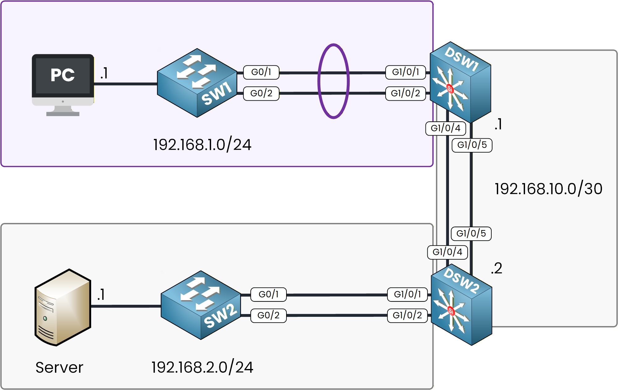
Figure 2 - PAgP EtherChannel Configuration Topology
Configuring SW1
Let’s start by connecting to SW1 and grouping interfaces GigabitEthernet 0/1 and 0/2 into a single EtherChannel.
SW1# configure terminal SW1(config)# interface range gigabitEthernet 0/1-2 SW1(config-if-range)# channel-group 1 mode ? active Enable LACP unconditionally auto Enable PAgP only if a PAgP device is detected desirable Enable PAgP unconditionally on Enable Etherchannel only passive Enable LACP only if a LACP device is detectedAmong the available modes, desirable and auto belong to PAgP.
We’ll choose desirable so the switch actively forms the EtherChannel.SW1(config-if-range)# channel-group 1 mode desirable Creating a port-channel interface Port-channel 1 %LINEPROTO-5-UPDOWN: Line protocol on Interface GigabitEthernet0/1, changed state to up %LINEPROTO-5-UPDOWN: Line protocol on Interface GigabitEthernet0/2, changed state to upAt this stage, the logical interface Port-channel 1 has been created, and both links are now bundled.
However, the EtherChannel is still inactive since the opposite switch is not yet configured.Let’s now enable trunking on this new Port-Channel.
Set Port-Channel as Trunk
To enable trunking, we apply the
switchport mode trunkcommand under the Port-Channel interface.SW1(config)# interface po1 SW1(config-if)# switchport mode trunkThat’s it. The logical interface is now acting as a trunk.
Let’s check the EtherChannel status to confirm the configuration.Check EtherChannel Status
The
show etherchannel summarycommand displays all EtherChannels configured on the device.
Here, Po1 is flagged as SD, which means the EtherChannel is Layer 2 (S) but currently Down (D).SW1# show etherchannel summary Flags: D - down P - in port-channel I - stand-alone s - suspended H - Hot-standby (LACP only) R - Layer3 S - Layer2 U - in use f - failed to allocate aggregator u - unsuitable for bundling w - waiting to be aggregated d - default port Number of channel-groups in use: 1 Number of aggregators: 1 Group Port-channel Protocol Ports ------+-------------+-----------+---------------------------------------------- 1 Po1(SD) PAgP Gig0/1(I) Gig0/2(I)This is perfectly normal for now, the opposite switch hasn’t been configured yet.
Configuring DSW1
Now, let’s move to DSW1 and configure the same EtherChannel.
We’ll bundle GigabitEthernet 1/0/1 and 1/0/2 into Port-Channel 1 using desirable mode.
We could have used auto, but using desirable on both sides ensures negotiation succeeds immediately.DSW1# configure terminal DSW1(config)# interface range g1/0/1-2 DSW1(config-if-range)# channel-group 1 mode desirable Creating a port-channel interface Port-channel 1The logical interface Po1 has now been created.
Next, let’s enable trunking on it.Set Port-Channel as Trunk
We’ll apply the same principle: enable trunking directly under the Port-Channel interface.
DSW1(config)# interface po1 DSW1(config-if)# switchport mode trunkLet’s now verify if the EtherChannel is up and operational.
Check EtherChannel Status
The
show etherchannel summaryoutput now shows SU, indicating that the EtherChannel is Layer 2 (S) and Up (U) which means it’s working properly.DSW1# show etherchannel summary Flags: D - down P - in port-channel I - stand-alone s - suspended H - Hot-standby (LACP only) R - Layer3 S - Layer2 U - in use f - failed to allocate aggregator u - unsuitable for bundling w - waiting to be aggregated d - default port Number of channel-groups in use: 1 Number of aggregators: 1 Group Port-channel Protocol Ports ------+-------------+-----------+---------------------------------------------- 1 Po1(SU) PAgP Gig1/0/1(P) Gig1/0/2(P)Each physical interface now shows (P), confirming it’s actively participating in the bundle.
Verify Trunk Configuration
We can also confirm that the trunk is correctly operational using the
show interfaces trunkcommand.DSW1# show interfaces trunk Port Mode Encapsulation Status Native vlan Po1 on 802.1q trunking 1 Port Vlans allowed on trunk Po1 1-1005 Port Vlans allowed and active in management domain Po1 1 Port Vlans in spanning tree forwarding state and not pruned Po1 nonePerfect, the EtherChannel is now up, trunking, and fully operational.
You’ve successfully configured a Layer 2 EtherChannel using PAgP.Answer the question below
Which PAgP mode actively tries to form an EtherChannel on its own?
In this step, you will configure an EtherChannel between SW2 and DSW2 using LACP.
Unlike PAgP, LACP follows the IEEE 802.3ad standard, which means it can work across devices from different vendors.
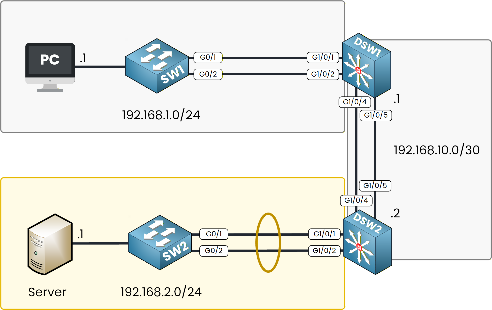
Figure 3 - LACP EtherChannel Configuration Topology
Configuring SW2
Let’s start by connecting to SW2.
You will group GigabitEthernet 0/1 and 0/2 into a single logical interface called Port-Channel 2.SW2(config)# int range g0/1-2 SW2(config-if-range)# channel-group 2 mode ? active Enable LACP unconditionally auto Enable PAgP only if a PAgP device is detected desirable Enable PAgP unconditionally on Enable Etherchannel only passive Enable LACP only if a LACP device is detectedYou probably remember the PAgP modes from the previous step.
This time, the available LACP modes are active and passive.
Choose active mode so the switch initiates the negotiation process.SW2(config-if-range)# channel-group 2 mode active Creating a port-channel interface Port-channel 2 %LINEPROTO-5-UPDOWN: Line protocol on Interface GigabitEthernet0/1, changed state to up %LINEPROTO-5-UPDOWN: Line protocol on Interface GigabitEthernet0/2, changed state to upThe Port-Channel interface has now been created.
Both links are bundled, but the EtherChannel is not operational yet because the other side is not configured.Set Port-Channel as Trunk
Now it’s time to make the Port-Channel a trunk so VLANs can pass through.
Apply the trunk configuration directly under the logical interface.SW2(config)# interface po2 SW2(config-if)# switchport mode trunkThe logical trunk is now ready.
Let’s check the EtherChannel status before moving to DSW2.Verifying SW2
Use the following command to verify the EtherChannel configuration.
SW2# show etherchannel summary Flags: D - down P - in port-channel I - stand-alone s - suspended H - Hot-standby (LACP only) R - Layer3 S - Layer2 U - in use f - failed to allocate aggregator u - unsuitable for bundling w - waiting to be aggregated d - default port Number of channel-groups in use: 1 Number of aggregators: 1 Group Port-channel Protocol Ports ------+-------------+-----------+---------------------------------------------- 2 Po2(SD) LACP Gig0/1(I) Gig0/2(I)If you see SD, it means the EtherChannel is Layer 2 but still down.
That’s completely normal for now since DSW2 hasn’t been configured yet.Configuring DSW2
Next, connect to DSW2 and create the same bundle.
Make sure to use the same channel group number and mode on both sides.
You will also use LACP in active mode.DSW2# conf t Enter configuration commands, one per line. End with CNTL/Z. DSW2(config)# int range g1/0/1-2 DSW2(config-if-range)# channel-group 2 mode active Creating a port-channel interface Port-channel 2Once the bundle is created, configure the logical interface as a trunk.
DSW2(config)# int po2 DSW2(config-if)# switchport mode trunkVerifying DSW2
Now let’s verify if the EtherChannel is operational.
Use the same command as before to display the current state.DSW2# show etherchannel summary Flags: D - down P - in port-channel I - stand-alone s - suspended H - Hot-standby (LACP only) R - Layer3 S - Layer2 U - in use f - failed to allocate aggregator u - unsuitable for bundling w - waiting to be aggregated d - default port Number of channel-groups in use: 1 Number of aggregators: 1 Group Port-channel Protocol Ports ------+-------------+-----------+---------------------------------------------- 2 Po2(SU) LACP Gig1/0/1(P) Gig1/0/2(P)The SU flag means that the EtherChannel is up and running at Layer 2.
Each interface marked with P confirms that it is actively participating in the bundle.You can also confirm the trunk configuration with the next command.
DSW2# show interface trunk Port Mode Encapsulation Status Native vlan Po2 on 802.1q trunking 1 Port Vlans allowed on trunk Po2 1-1005 Port Vlans allowed and active in management domain Po2 1 Port Vlans in spanning tree forwarding state and not pruned Po2 1Everything is configured correctly.
You have now completed the LACP EtherChannel configuration between SW2 and DSW2.Answer the question below
Which LACP mode actively initiates EtherChannel negotiation?
In this step, you will configure a Layer 3 EtherChannel between DSW1 and DSW2.
Unlike the previous EtherChannels, this one will not carry VLANs because the interfaces will operate at Layer 3.
Figure 4 - Layer 3 EtherChannel Configuration Topology
Configuring DSW1
Let’s start with DSW1.
You will select interfaces GigabitEthernet 1/0/4 and 1/0/5, disable switchport mode to move them to Layer 3, and then bundle them together.DSW1(config)# int range g1/0/4-5 DSW1(config-if-range)# no switchport DSW1(config-if-range)# channel-group 3 mode ? active Enable LACP unconditionally auto Enable PAgP only if a PAgP device is detected desirable Enable PAgP unconditionally on Enable Etherchannel only passive Enable LACP only if a LACP device is detectedYou can see the available options again.
Since we want a static EtherChannel that doesn’t rely on negotiation, choose the on mode.DSW1(config-if-range)# channel-group 3 mode on Creating a port-channel interface Port-channel 3Once the bundle is created, assign an IP address to the logical Port-Channel interface.
This IP will be used as the next-hop for routing between both switches.DSW1(config)# int po3 DSW1(config-if)# ip address 192.168.10.1 255.255.255.252Your Layer 3 Port-Channel is now configured on DSW1.
Let’s repeat the process on DSW2.Configuring DSW2
On DSW2, we will select the same interface range and follow the same steps.
This ensures that both switches form the bundle correctly.DSW2(config)# int range g1/0/4-5 DSW2(config-if-range)# no switchport DSW2(config-if-range)# channel-group 3 mode on Creating a port-channel interface Port-channel 3Next, assign an IP address on the Port-Channel interface that belongs to the same subnet as DSW1.
DSW2(config)# interface port-channel 3 DSW2(config-if)# ip address 192.168.10.2 255.255.255.252Perfect.
You’ve just created a Layer 3 EtherChannel between DSW1 and DSW2.
Let’s now verify that everything is working properly.Verifying the Layer 3 EtherChannel
The
show etherchannel summarycommand should display the new Port-Channel as a Layer 3 interface.
Look for the RU flag, which means the EtherChannel is operating at Layer 3 and is currently up.DSW1# show etherchannel summary Flags: D - down P - in port-channel I - stand-alone s - suspended H - Hot-standby (LACP only) R - Layer3 S - Layer2 U - in use f - failed to allocate aggregator u - unsuitable for bundling w - waiting to be aggregated d - default port Number of channel-groups in use: 2 Number of aggregators: 2 Group Port-channel Protocol Ports ------+-------------+-----------+---------------------------------------------- 3 Po3(RU) - Gig1/0/4(P) Gig1/0/5(P)Notice the dash under the Protocol column.
It indicates that no negotiation protocol such as PAgP or LACP is being used.
This is expected since the EtherChannel was created in static mode with the on keyword.Run the same command on DSW2 to confirm that both sides are synchronized.
DSW2# show etherchannel summary Flags: D - down P - in port-channel I - stand-alone s - suspended H - Hot-standby (LACP only) R - Layer3 S - Layer2 U - in use f - failed to allocate aggregator u - unsuitable for bundling w - waiting to be aggregated d - default port Number of channel-groups in use: 2 Number of aggregators: 2 Group Port-channel Protocol Ports ------+-------------+-----------+---------------------------------------------- 3 Po3(RU) - Gig1/0/4(P) Gig1/0/5(P)Both interfaces are part of the bundle and fully operational.
You now have a routed EtherChannel between DSW1 and DSW2.Answer the question below
Which EtherChannel mode should you use to create a static Layer 3 EtherChannel without any negotiation protocol?
Now that the Layer 3 EtherChannel is configured and operational, the next step is to enable routing between the two switches. This will allow the PC and the Server, located in different VLANs, to communicate through the new Layer 3 link.

Figure 5 - Static Route configuration for EtherChannel Lab
Configuring Static Routing on DSW1
By default, multilayer switches can switch at Layer 2 but cannot route IP traffic until routing is explicitly enabled.
Let’s start by activating IP routing on DSW1.DSW1(config)# ip ? route Establish static routes routing Enable IP routing scp Scp commands DSW1(config)# ip routingOnce IP routing is enabled, we can add a static route that tells DSW1 how to reach the remote network connected to DSW2.
DSW1(config)# ip route 192.168.2.0 255.255.255.0 192.168.10.2This command means that the 192.168.2.0/24 network can be reached via 192.168.10.2, which is DSW2’s IP address on the EtherChannel link.
Configuring Static Routing on DSW2
Now let’s configure DSW2 in a similar way.
Just like on DSW1, we’ll begin by enabling IP routing so the switch can forward packets between networks.DSW2(config)# ip ? route Establish static routes routing Enable IP routing scp Scp commandsOnce routing is enabled, we’ll add a static route pointing toward DSW1.
This will tell DSW2 how to reach the VLAN 1 network connected to the other switch.DSW2(config)# ip route 192.168.1.0 255.255.255.0 192.168.10.1In this case, packets destined for the 192.168.1.0/24 network will be forwarded through 192.168.10.1, which is DSW1’s IP address on the EtherChannel.
Verify the routing table
It’s time to check if the static routes were successfully added.
Use the show ip route command on both switches to confirm that each device has the correct entries.DSW1# show ip route Codes: C - connected, S - static, I - IGRP, R - RIP, M - mobile, B - BGP D - EIGRP, EX - EIGRP external, O - OSPF, IA - OSPF inter area N1 - OSPF NSSA external type 1, N2 - OSPF NSSA external type 2 E1 - OSPF external type 1, E2 - OSPF external type 2, E - EGP i - IS-IS, L1 - IS-IS level-1, L2 - IS-IS level-2, ia - IS-IS inter area * - candidate default, U - per-user static route, o - ODR P - periodic downloaded static route Gateway of last resort is not set C 192.168.1.0/24 is directly connected, Vlan1 S 192.168.2.0/24 [1/0] via 192.168.10.2 C 192.168.10.0/24 is directly connected, Port-channel3DSW2# show ip route Codes: C - connected, S - static, I - IGRP, R - RIP, M - mobile, B - BGP D - EIGRP, EX - EIGRP external, O - OSPF, IA - OSPF inter area N1 - OSPF NSSA external type 1, N2 - OSPF NSSA external type 2 E1 - OSPF external type 1, E2 - OSPF external type 2, E - EGP i - IS-IS, L1 - IS-IS level-1, L2 - IS-IS level-2, ia - IS-IS inter area * - candidate default, U - per-user static route, o - ODR P - periodic downloaded static route Gateway of last resort is not set S 192.168.1.0/24 [1/0] via 192.168.10.2 C 192.168.2.0/24 is directly connected, Vlan1 C 192.168.10.0/24 is directly connected, Port-channel3You can now see that each switch has a static route to reach the opposite VLAN network through the Layer 3 EtherChannel.
At this point, routing between the two distribution switches is fully operational.Answer the question below
What must you enable on a multilayer switch before ip route will actually work?
Now that all EtherChannels and static routes have been configured, it’s time to verify that everything works as expected.
In this step, we’ll test the end-to-end communication between the PC and the Server to confirm that the Layer 3 EtherChannel and routing are functioning properly.
Figure 6 - Communication Success
Testing Connectivity from the PC
From the PC, we’ll try to reach the Server’s IP address, which is located on a different VLAN.
This will test not only the EtherChannel configurations but also the static routes configured on both distribution switches.On the PC, open the Command Prompt and use the
pingcommand to send ICMP packets toward the Server.C:\> ping 192.168.2.1 Pinging 192.168.2.1 with 32 bytes of data: Reply from 192.168.2.1: bytes=32 time<1ms TTL=126 Reply from 192.168.2.1: bytes=32 time<1ms TTL=126 Reply from 192.168.2.1: bytes=32 time<1ms TTL=126 Reply from 192.168.2.1: bytes=32 time<1ms TTL=126 Ping statistics for 192.168.2.1: Packets: Sent = 4, Received = 4, Lost = 0 (0% loss), Approximate round trip times in milli-seconds: Minimum = 0ms, Maximum = 0ms, Average = 0msIf you receive four successful replies like in the example above, it means that:
The Layer 2 EtherChannels (PAgP and LACP) are properly configured and forwarding traffic
The Layer 3 EtherChannel between DSW1 and DSW2 is operational
The static routes on both switches are correctly pointing to each other’s networks
Wrapping Up
Great job, the ping test confirms full connectivity between the PC and the Server.
You’ve successfully configured and verified EtherChannel using PAgP, LACP, and Static Layer 3 modes.
Your network now benefits from higher bandwidth, link redundancy, and loop-free communication.Answer the question below