In the previous lesson, you bundled multiple switch ports into one logical link with Layer 2 EtherChannel.
Now we move on to Layer 3 EtherChannel. The idea is the same: combine several physical interfaces into one Port-Channel. The difference is that the Port-Channel is treated as a routed interface and can be assigned an IP address instead of functioning as a switchport.
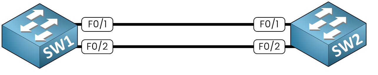
Figure 1 – Two switches linked before Layer 3 EtherChannel.
This type of configuration is supported on multilayer switches and routers. In Cisco's three-tier design (Access → Distribution → Core), it is commonly used between the Distribution and Core layers to ensure reliable, high-bandwidth interconnections.
In this lab, two multilayer switches (SW1 and SW2) will bundle interfaces F0/1 and F0/2 into Port-Channel 1.
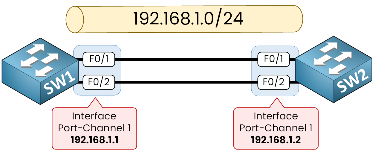
Figure 2 – Port-Channel Setup
Each Port-Channel interface will then be assigned an IP address from the 192.168.1.0/24 network.
Let's dive into the configuration.
Answer the question below
Configuration on SW1
Step 1 - Enable IP Routing
Since we are working with multilayer switches, we must first enable the global routing function.
By default, switches operate only at Layer 2. Theip routingcommand allows the switch to forward packets based on IP addresses.SW1# configure terminal Enter configuration commands, one per line. End with CNTL/Z. SW1(config)# ip routingAt this point, SW1 is ready to handle Layer 3 interfaces.
Step 2 – Convert Interfaces to Routed Ports and Create the EtherChannel (SW1)
Select the physical interfaces that will participate in the Layer 3 EtherChannel.
SW1(config)# interface range f0/1-2Convert the interfaces from Layer 2 switchports to Layer 3 routed ports.
SW1(config-if-range)# no switchportCreate a static EtherChannel using mode on.
SW1(config-if-range)# channel-group 1 mode on
Creating a port-channel interface Port-channel 1
%LINK-5-CHANGED: Interface Port-channel1, changed state to up
%LINEPROTO-5-UPDOWN: Line protocol on Interface Port-channel1, changed state to up
SW1(config-if-range)# exit
The system automatically creates the logical interface Port-Channel 1.
Step 3 – Assign an IP Address to the Port-Channel (SW1)
Configure the logical Port-Channel interface as a routed interface by assigning an IP address.
40 % Complete: you’re making great progress
Ready to pass your CCNA exam?