Voice VLAN

1. History of Voice VLAN

Voice VLAN Cisco created is a powerful feature that allows you to separate and prioritize voice traffic from data traffic efficiently. In this guide, we’ll walk you through its purpose, configuration, and how it works step by step.

Let’s take a step back.

Before Cisco introduced the Voice VLAN feature, things were a bit messier. If you had a computer and an IP phone at the same desk, you needed two Ethernet cables and two switch ports.

Voice VLAN Cisco diagram showing old setup with two switch ports: one for VLAN 10 data and one for VLAN 20 voice

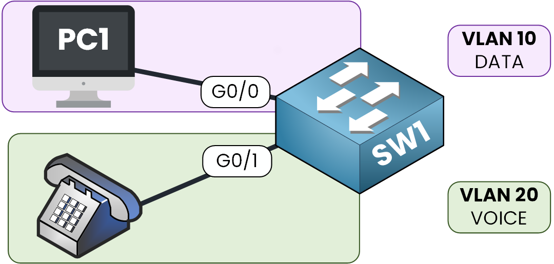
Figure 1 – Before Voice VLAN, each device required a dedicated switch port

Each device had its own port, both configured in access mode:

  • One port for VLAN 10 (DATA)

  • One port for VLAN 20 (VOICE)

Switch port configuration for VLAN 10 and VLAN 20 with separate cabling for PC and IP phone – inefficient setup before voice VLAN

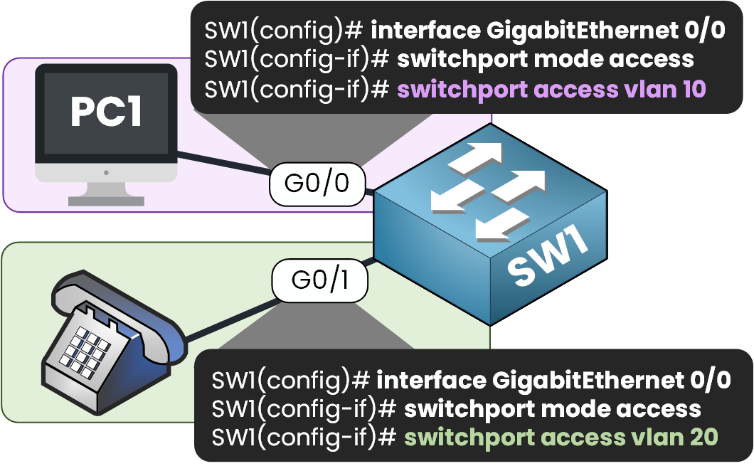
Figure 2 – Each port is manually configured with its own VLAN for data or voice

This setup worked but let’s be honest, it wasn’t efficient:

  • You were burning two switch ports per user

  • You had to run more cabling

  • And you had to configure and maintain twice as many ports

As your network grows, this quickly turns into a scalability nightmare.

2. Voice VLAN Creation

To solve this inefficiency, Cisco introduced the Voice VLAN feature.

Modern IP phones, like the Cisco 79xx series, have a built-in mini switch with two ports:

  • One that connects directly to the switch

  • One that connects to your PC

Voice VLAN Cisco diagram showing PC and IP phone sharing the same access link using VLAN 10 for data and VLAN 20 for voice

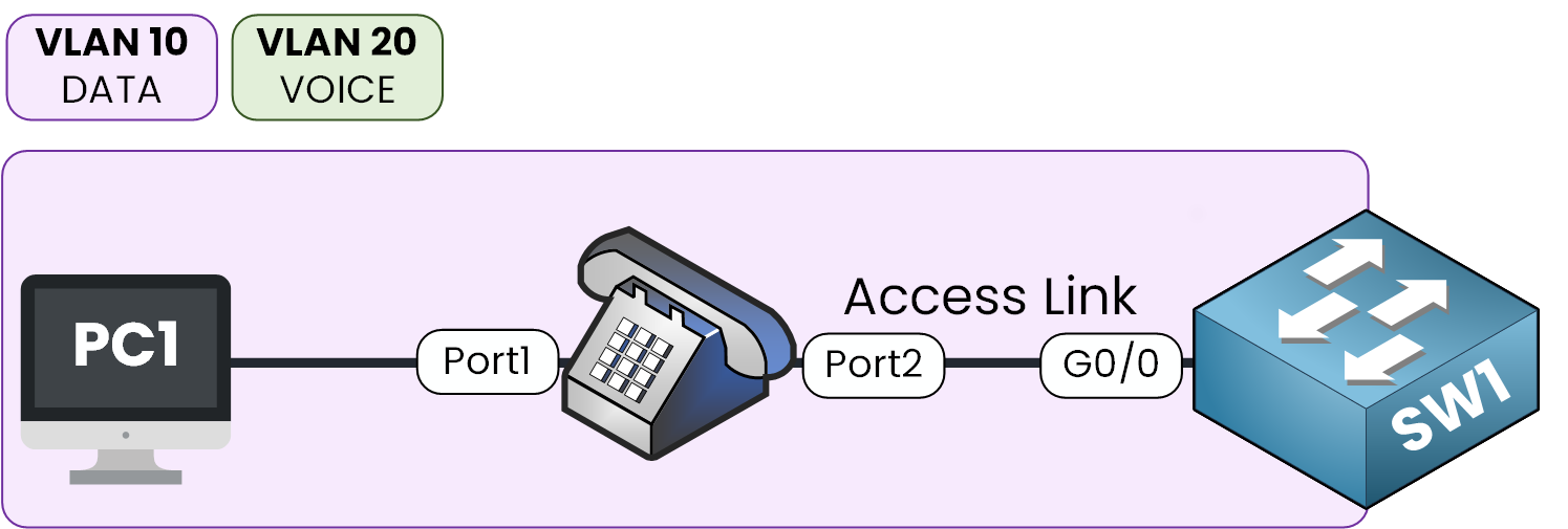
Figure 3 – PC and phone share one port using Voice VLAN and the phone’s mini switch

This setup allows both the PC and the phone to share the same Ethernet link on the switch.

3. How Voice VLAN Works ?

Alright, so how does all this actually work?

Let's say you configured your switch port like this:

  • Access VLAN: 10 (for Data)

  • Voice VLAN: 20 (for Voice)

Now imagine traffic coming from the PC and the IP phone:

  • The PC sends untagged frames → the switch associates them with VLAN 10 (DATA)

  • The IP phone tags its voice traffic using 802.1Q marking it as VLAN 20 (VOICE)

Voice VLAN Cisco diagram showing how the IP phone tags traffic as VLAN 20 while PC traffic remains untagged for VLAN 10

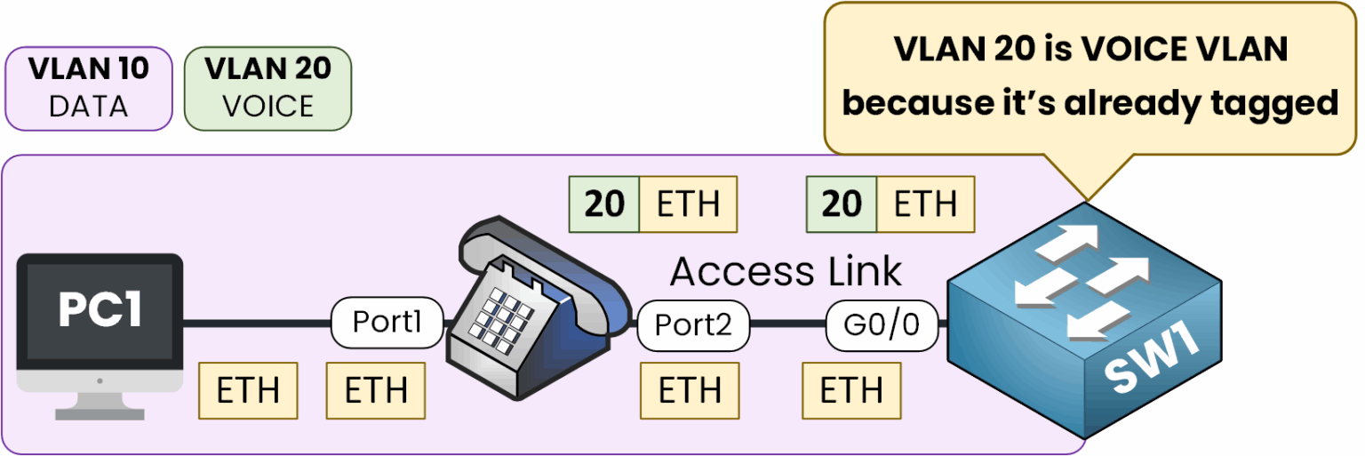
Figure 4 – Voice VLAN uses 802.1Q tagging while data remains untagged

Your switch port GigabitEthernet 0/0 is still configured in access mode but it now understands two types of traffic:

  • Untagged = Data VLAN

  • Tagged = Voice VLAN

Voice Traffic is Prioritized

What's is also very cool is that voice traffic is prioritized to ensure a good Quality of Service.

As you can see here, the IP phone tags voice traffic by default with 802.1q Class of Service (CoS) = 5

Voice VLAN and Data VLAN on the same port using IP phone passthrough with 802.1p CoS 5 prioritization

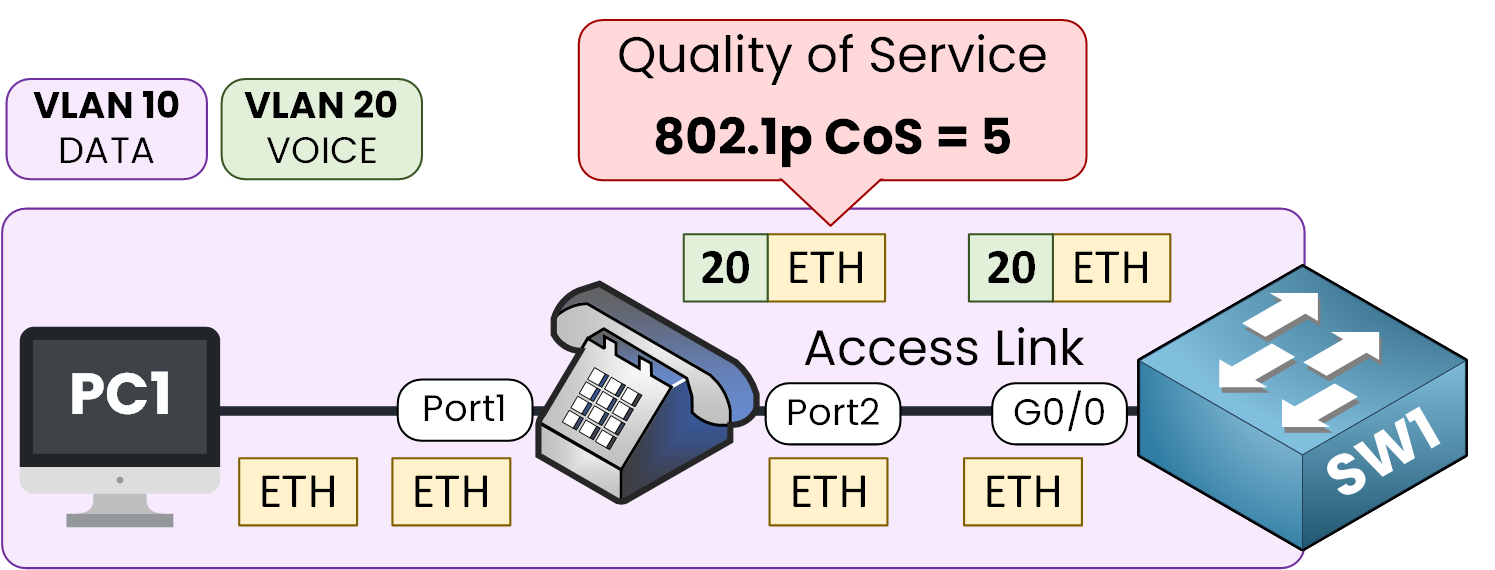
Figure 5 – Voice traffic is tagged with CoS 5 to ensure quality of service.

4. Configuring Voice VLAN

Let’s walk through the config step-by-step. We’ll use:

  • VLAN 10 for DATA

  • VLAN 20 for VOICE

Configuring Voice VLAN with switchport access vlan 10 and switchport voice vlan 20 for PC and IP phone on a shared access port

Figure 6 – Voice VLAN configuration assigns data and voice VLANs to the same access port

1. Create the VLANs

SW1(config)# vlan 10
SW1(config-vlan)# name DATA
SW1(config-vlan)# exit

SW1(config)# vlan 20
SW1(config-vlan)# name VOICE
SW1(config-vlan)# exit

2. Configure the Interface

SW1(config)# interface GigabitEthernet 0/0
SW1(config-if)# switchport mode access
SW1(config-if)# switchport access vlan 10
SW1(config-if)# switchport voice vlan 20
SW1(config-if)# exit

By configuring the switchport this way, you're telling the switch:

  • The port expects untagged traffic from the PC → it assigns it to VLAN 10.

  • It also accepts tagged voice traffic from the phone → and places it in VLAN 20.

3. How the Phone Learns Its Voice VLAN

Alright, now here’s a key question:

How does the IP phone know it should tag its voice traffic with VLAN 20?

That’s where CDP (Cisco Discovery Protocol) comes into play.

Voice VLAN Cisco diagram showing how a switch uses CDP to inform the IP phone to tag voice traffic with VLAN 20

Figure 7 – The switch uses CDP to tell the phone which Voice VLAN to use

  • The switch announces the voice VLAN via CDP.

  • The Cisco IP phone listens and learns which VLAN it should use to tag voice traffic.

  • The IP phone also advertises itself using CDP, informing the switch about its presence and capabilities.

In simple terms, the switch is basically saying:

"Hey phone, please tag your voice traffic with VLAN 20."

Without CDP (or LLDP-MED), the phone won’t know it should use VLAN 20 and might end up sending untagged voice traffic on the data VLAN

To ensure CDP is enabled on the switch:

SW1(config)# cdp run

To verify that the switch sees the IP phone:

SW1# show cdp neighbors

Capability Codes: R - Router, T - Bridge, B - Source Route Bridge
                  S - Switch, H - Host, I - IGMP, r - Repeater, P - Phone,
                  D - Remote, M - Two-port Mac Relay

Device ID        Local Intrfce     Holdtme     Capability     Platform        Port ID  
SEP00234BCDA91   Gig 0/0           140         H P M          IP Phone 7960   Port 1

Need more detail?

SW1# show cdp neighbors detail

Device ID: SEP00234BCDA91  
IP address: 10.1.20.55  
Platform: Cisco IP Phone 7960, Capabilities: Host Phone Two-port Mac Relay  
Interface: GigabitEthernet0/0, Port ID (outgoing): Port 1  
Holdtime: 138 seconds  
Second Port Status: Down  

Software Version:  
term70.default  

Advertisement Version: 2  
Duplex: full  
Power usage: 9.800 Watts  
Power request ID: 14010  
Requested power levels: 9800 6000 0 0 0  

By default, Cisco IP Phones send CDP messages to advertise themselves.

Other phones may use LLDP-MED (Link Layer Discovery Protocol - Media Endpoint Discovery) for this purpose.

5. Verifying Voice VLAN

Alright! Now that the configuration is done, it’s time to verify everything is working the way it should.

Check Interface Settings

We can run this command on our switch:

SW1# show interfaces GigabitEthernet 0/0 switchport 
Name: Gi0/0
Switchport: Enabled
Administrative Mode: static access
Operational Mode: static access
Administrative Trunking Encapsulation: negotiate
Operational Trunking Encapsulation: native
Negotiation of Trunking: Off
Access Mode VLAN: 10 (DATA)
Trunking Native Mode VLAN: 1 (default)
Administrative Native VLAN tagging: enabled
Voice VLAN: 20 (VOICE)
  • The port is in access mode

  • It assigns untagged traffic to VLAN 10

  • It recognizes tagged voice traffic and maps it to VLAN 20

So far, it's good!

Check Allowed VLANs

Now let’s dig a bit deeper. Even though the port is in access mode, voice VLAN behavior introduces some trunk-like characteristics.

SW1# show interfaces GigabitEthernet 0/0 trunk
Port        Mode             Encapsulation  Status        Native vlan
Gi0/0       off              negotiate      not-trunking  1

Port        Vlans allowed on trunk
Gi0/0       10,20

Port        Vlans allowed and active in management domain
Gi0/0       10,20

Port        Vlans in spanning tree forwarding state and not pruned
Gi0/0       10,20

Even though the interface is not a trunk, you can see that both VLAN 10 and 20 are allowed and active. That’s the magic of voice VLAN Cisco it makes an access port act almost like a trunk but with a specific rule: only one VLAN for data (untagged) and one for voice (tagged).

6. Conclusion

Remember the key points:

  • The port is in access mode with a data VLAN (untagged)

  • You add a Voice VLAN to handle tagged voice traffic

  • CDP must be enabled so the switch tells the IP phone which VLAN to use

This is exactly how a typical Voice VLAN Cisco setup ensures voice traffic is isolated and prioritized