A trunk link is a Layer 2 connection that carries traffic from multiple VLANs between switches.
Without trunking, each VLAN would remain confined to the switch where it was created.Why Trunking Is Needed
To understand why trunking is important, let’s look at a simple example.
Below, several VLANs are created on two switches.
PC1 and PC3 both belong to VLAN 10, but they are connected to different switches.
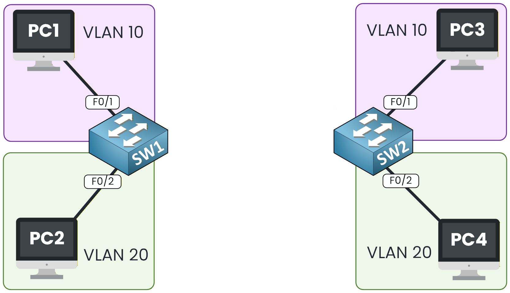
Figure 1 – VLANs on Different Switches
Even though both devices belong to VLAN 10, they still cannot communicate because they are located on separate switches.
To allow communication between these two devices, we need two things:
A physical link connects the switches.
802.1Q trunking is enabled on that link.
Figure 2 – Trunk Link Between Switches
By enabling trunking, we allow VLAN 10 and VLAN 20 traffic to pass through the inter-switch link.
This means each VLAN can extend beyond a single switch, VLAN 10 on SW1 can now reach VLAN 10 on SW2, and so on.How the Trunk Link Connects VLANs
Let’s walk through an example to see this in action.
PC1 wants to send traffic to PC3.
SW1 receives the frame on interface G0/1, which is an access port in VLAN 10.
Since PC3 is connected to another switch, SW1 forwards the frame to SW2 over the trunk link.
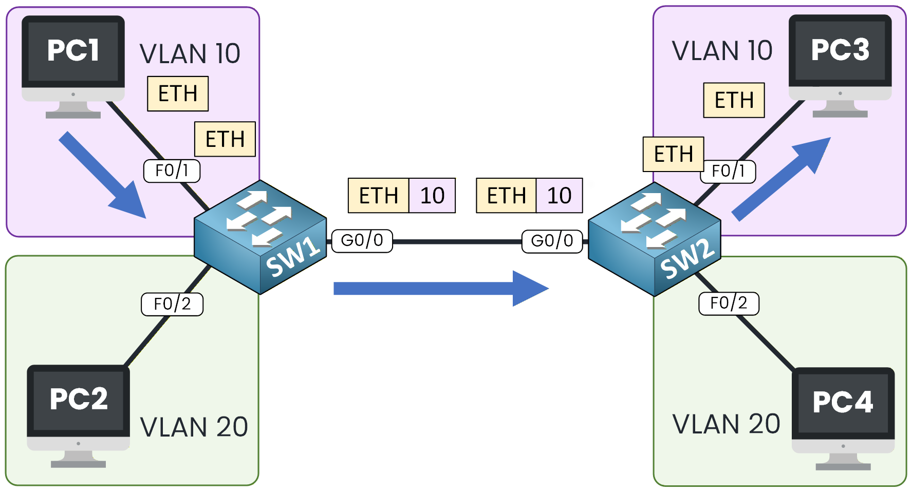
Figure 3 – VLAN Tagging with 802.1Q Trunking
SW2 receives the frame, identifies it as part of VLAN 10, and forwards it to PC3.
From the user’s perspective, both PCs appear to be on the same local network, even though they are on different switches.This is the purpose of trunking:
it extends VLANs across multiple switches while keeping traffic from each VLAN logically separated.
Now that we understand what trunking does, the next step is to see how it actually works, how VLAN information is added, transported, and removed from frames as they cross the trunk.Answer the question below
Now that you understand the purpose of trunking, let’s see how it actually works inside an Ethernet frame.
We’ll go step by step through the process a VLAN-tagged frame follows as it travels from one switch to another across a trunk link.
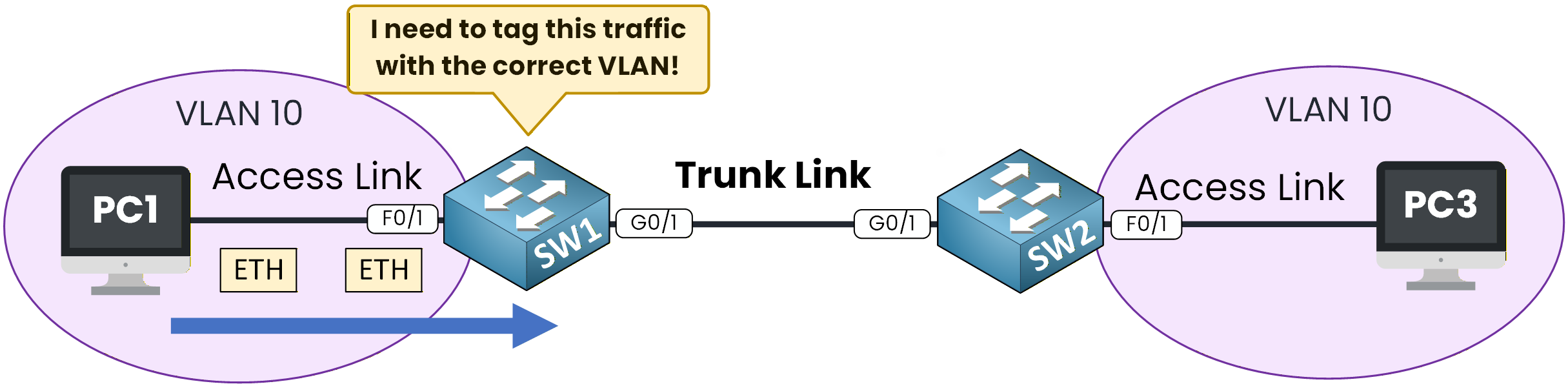
Figure 4 – VLAN Tagging Process on a Trunk Link
Step 1 – Frame Ingress on SW1
PC1 belongs to VLAN 10, so when it sends a frame, it arrives on SW1’s G0/1 access port, which is assigned to VLAN 10.
Inside the switch, the frame is internally associated with VLAN 10, but it is still a standard Ethernet frame at this point, no VLAN tag has been added yet.
Step 2 – Tagging for the TrunkBecause the destination (PC3) is located on another switch, SW1 must send the frame over the trunk link to SW2.
Before doing so, SW1 adds an 802.1Q header to the frame, a 4-byte field inserted just after the source MAC address.
This header identifies the VLAN to which the frame belongs and allows multiple VLANs to share a single physical link safely.Figure 5 – 802.1Q Frame Structure with VLAN Tag
The IEEE 802.1Q protocol defines this tagging method. It’s a vendor-neutral standard that replaced Cisco’s older ISL protocol.
The 802.1Q header includes:
12 bits for the VLAN ID (1–4094; 0 and 4095 are reserved)
3 bits for priority marking (802.1p QoS)
1 bit called the CFI or DEI bit (not required at CCNA level)
In this example, SW1 sets the VLAN ID (VID) to 10, marking the frame as belonging to VLAN 10.
Figure 6 – VLAN Tag with VID Set to 10 in 802.1Q Frame
Step 3 – Transit over the trunk
The tagged frame now travels across the trunk link, keeping its VLAN ID (10). Every switch along the path can read this tag and use it to keep VLAN 10’s traffic separate from other VLANs such as VLAN 20.
Figure 7 – Trunk Frame Transit and Egress
Step 4 – Frame egress on SW2
When the frame reaches SW2’s trunk port, the switch removes the 802.1Q header, restoring the original Ethernet frame.
Because the tag indicates VLAN 10, SW2 forwards the frame out of its G0/1 access port toward PC3.At this point, communication between PC1 and PC3 is complete.
This entire process, ingress, tagging, trunk transport, un-tagging, and delivery happens in a fraction of a second, allowing VLAN 10 to extend across multiple switches while keeping all VLANs logically isolated.Answer the question below
How many bits are reserved in an 802.1Q tag for the VLAN ID?
Now that you understand how trunking works, let’s configure it on Cisco switches using the CLI.
In this example, we’ll create a trunk link between SW1 and SW2 so that VLAN 10 and VLAN 20 can communicate between switches.Figure 8 – Initial Topology for 802.1Q Trunk Configuration
Before we begin, remember this:
Access ports carry traffic for a single VLAN (they connect to end devices).
Trunk ports carry traffic for multiple VLANs between switches.
This separation keeps broadcast domains isolated while still allowing VLANs to extend across multiple switches.
Step 1 – Configure the Trunk on SW1
Let’s start with SW1, which connects to SW2 through interface GigabitEthernet0/0.
Enter interface configuration mode
SW1# configure terminal SW1(config)# interface G0/0
Set the trunk encapsulation to 802.1Q
SW1(config-if)# switchport trunk encapsulation dot1q
This command specifies that the port will use the IEEE 802.1Q standard for VLAN tagging.
Enable trunking mode on the port
SW1(config-if)# switchport mode trunk
At this point, the interface is officially acting as a trunk link and will tag outgoing frames with the appropriate VLAN ID.
(Optional) Limit VLANs allowed on the trunk
SW1(config-if)# switchport trunk allowed vlan 10,20
By default, a trunk carries all VLANs. However, it’s a best practice to restrict it to the VLANs that actually need to pass through, in this case, VLANs 10 and 20.
Step 2 – Verify Trunk Status on SW1
Use the following command to confirm that the trunk is active and properly configured:
SW1# show interfaces trunk Port Mode Encapsulation Status Native vlan G0/0 on 802.1q trunking 1 Port Vlans allowed on trunk G0/0 10,20 Port Vlans in spanning tree forwarding state and not pruned G0/0 10,20
If the Status column shows trunking, your link is operational.
Step 3 – Mirror the Configuration on SW2
Now, repeat the same configuration on SW2, using the interface connected to SW1 (GigabitEthernet0/0):
SW2# configure terminal SW2(config)# interface G0/0 SW2(config-if)# switchport trunk encapsulation dot1q SW2(config-if)# switchport mode trunk SW2(config-if)# switchport trunk allowed vlan 10,20
Then verify with:
SW2# show interfaces trunk Port Mode Encapsulation Status Native vlan G0/0 on 802.1q trunking 1 Port Vlans allowed on trunk G0/0 10,20 Port Vlans in spanning tree forwarding state and not pruned G0/0 10,20
At this point, both switches share VLAN 10 and VLAN 20 through the trunk link.
Devices in VLAN 10 can now communicate across SW1 and SW2, and the same applies to VLAN 20.Step 4 – Quick Recap
Let’s summarize what you have done:
Command
Purpose
switchport trunk encapsulation dot1q
Defines 802.1Q as the tagging method
switchport mode trunk
Enables trunking on the interface
switchport trunk allowed vlan 10,20
Restricts VLANs allowed on the trunk
show interfaces trunk
Verifies trunk status and VLANs
Now that your trunk is operational, the next step is to explore the Dynamic Trunking Protocol (DTP), the mechanism that can automatically negotiate trunking between switches.
Answer the question below