In this lab, you will configure Standard ACLs, Extended ACLs, and Named ACLs in a simple network made of one router, two switches, two PCs, and one server.
This is your first hands-on ACL configuration.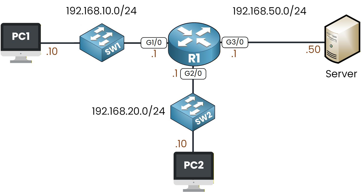
Figure 1 - ACL Configuration Lab Topology
You already learned the ACL core concepts and configuration commands in the previous lessons.
In this lab, we will apply everything in practice to see how ACLs behave on a real router.If you need a quick refresher on ACLs, you can revisit these lessons:
Your objective here is to apply different types of ACLs to control traffic between the PCs and the server.
You will create filters based on source addresses, destination addresses, and specific protocols.We will walk through everything step by step.
How to Begin
The topology above is already set up for you with all IP addresses, VLANs, and default gateways configured.
You can focus entirely on ACLs and run every command directly in the integrated CLI below.Lab Overview
Here is the structure we will follow throughout this lab:
Step 1 – Configure a Standard ACL
Step 2 – Configure an Extended ACL
Step 3 – Configure a Named ACL
Let’s get started.
Answer the question below
Click 'Complete' to continue
Before applying any filtering, take a moment to review the topology with me.
You can see that PC1 and PC2 are in two different subnets, and both can reach the Server through R1.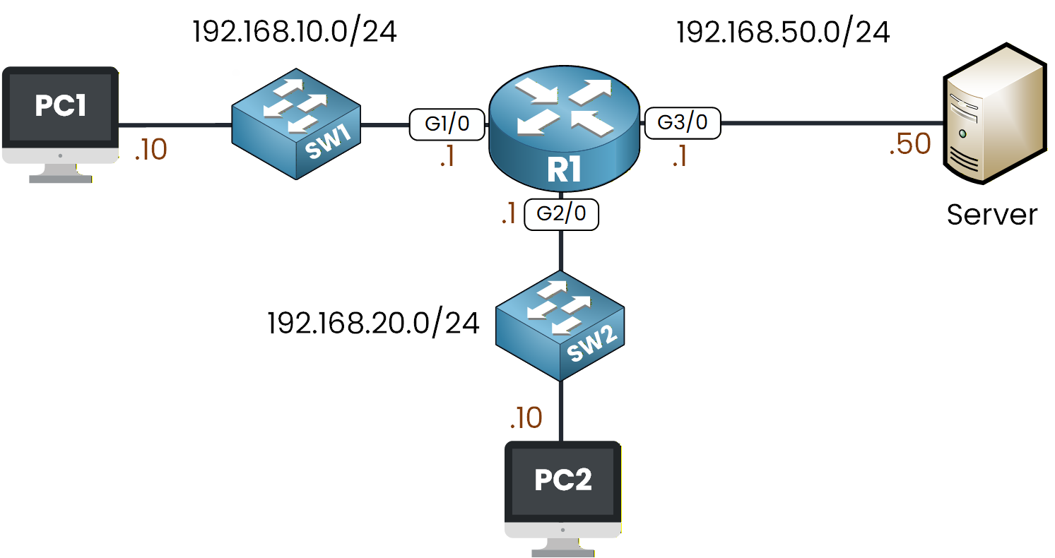
Figure 2 - ACL Configuration Lab Topology
Your objective here is simple:
I want you to block PC2's IP address from reaching the Server while still allowing PC1.
Since a Standard ACL filters traffic only on the source IP address, we will use one to match PC2’s address.
Create the Standard ACL
Let’s begin the configuration on R1.
R1# conf t
Enter configuration commands, one per line.  End with CNTL/Z.
R1(config)# ip access-list standard ?
  <1-99>  Standard IP access-list number
  WORD    Access-list name
R1(config)# ip access-list standard 10
For this example, we use the access-list number 10.
We start by defining the first condition, which is the deny statement.R1(config-std-nacl)# ? <1-2147483647> Sequence Number default Set a command to its defaults deny Specify packets to reject exit Exit from access-list configuration mode no Negate a command or set its defaults permit Specify packets to forward remark Access list entry commentLet’s deny PC2’s IP address.
R1(config-std-nacl)# deny host 192.168.20.10Now that PC2 is blocked, we allow all remaining traffic so the network continues to work normally.
R1(config-std-nacl)# permit ?
  A.B.C.D  Address to match
  any      Any source host
  host     A single host address

R1(config-std-nacl)# permit any
R1(config-std-nacl)# end
Your Standard ACL is now defined. You can confirm it with:
R1# show ip access-lists
Standard IP access list 10
    10 deny host 192.168.20.10
    20 permit any
At this stage, R1 knows what traffic to block, but nothing is enforced yet.
An ACL only becomes active once you apply it to an interface.Apply the Standard ACL
Standard ACLs should be placed as close to the destination as possible.
In this lab, the destination is the Server network 192.168.50.0/24, reachable through interface G3/0.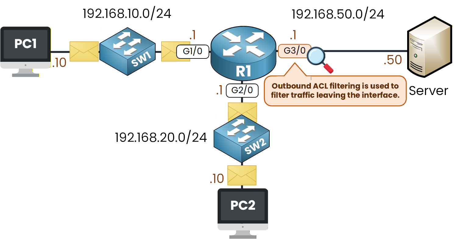
Figure 3 - Outbound ACL Filtering Behavior
We apply the ACL outbound on that interface.
R1(config)# int g3/0
R1(config-if)# ip ?
  access-group     Specify access control for packets
  address          Set the IP address of an interface
  authentication   authentication subcommands

R1(config-if)# ip access-group ?
  <1-199>  IP access list (standard or extended)
  WORD     Access-list name
Here, we attach ACL 10 and then we choose the direction:
R1(config-if)# ip access-group 10 ?
  in   inbound packets
  out  outbound packets
This gives us the final command:
R1(config)# interface g3/0
R1(config-if)# ip access-group 10 out
R1(config-if)# end
Your filtering rule is now active.
Verify the ACL Is Applied
Before testing traffic, let’s make sure the ACL is correctly attached to the interface.
R1# show ip interface g3/0
GigabitEthernet3/0 is up, line protocol is up (connected)
  Internet address is 192.168.50.1/24
  Broadcast address is 255.255.255.255
  Address determined by setup command
  MTU is 1500 bytes
  Helper address is not set
  Directed broadcast forwarding is disabled
  Outgoing access list is 10
  Inbound  access list is not set
Look for the line: Outgoing access list is 10.
If you see it, your ACL is exactly where it should be.
If not, simply go back and reapply it on the correct interface.Test the ACL
Now let’s check if your filtering works as expected.
First, from PC1:
C:\> ping 192.168.50.50

Pinging 192.168.50.50 with 32 bytes of data:

Reply from 192.168.50.50: bytes=32 time<1ms TTL=127
Reply from 192.168.50.50: bytes=32 time<1ms TTL=127
Reply from 192.168.50.50: bytes=32 time<1ms TTL=127
PC1 should reach the Server normally.
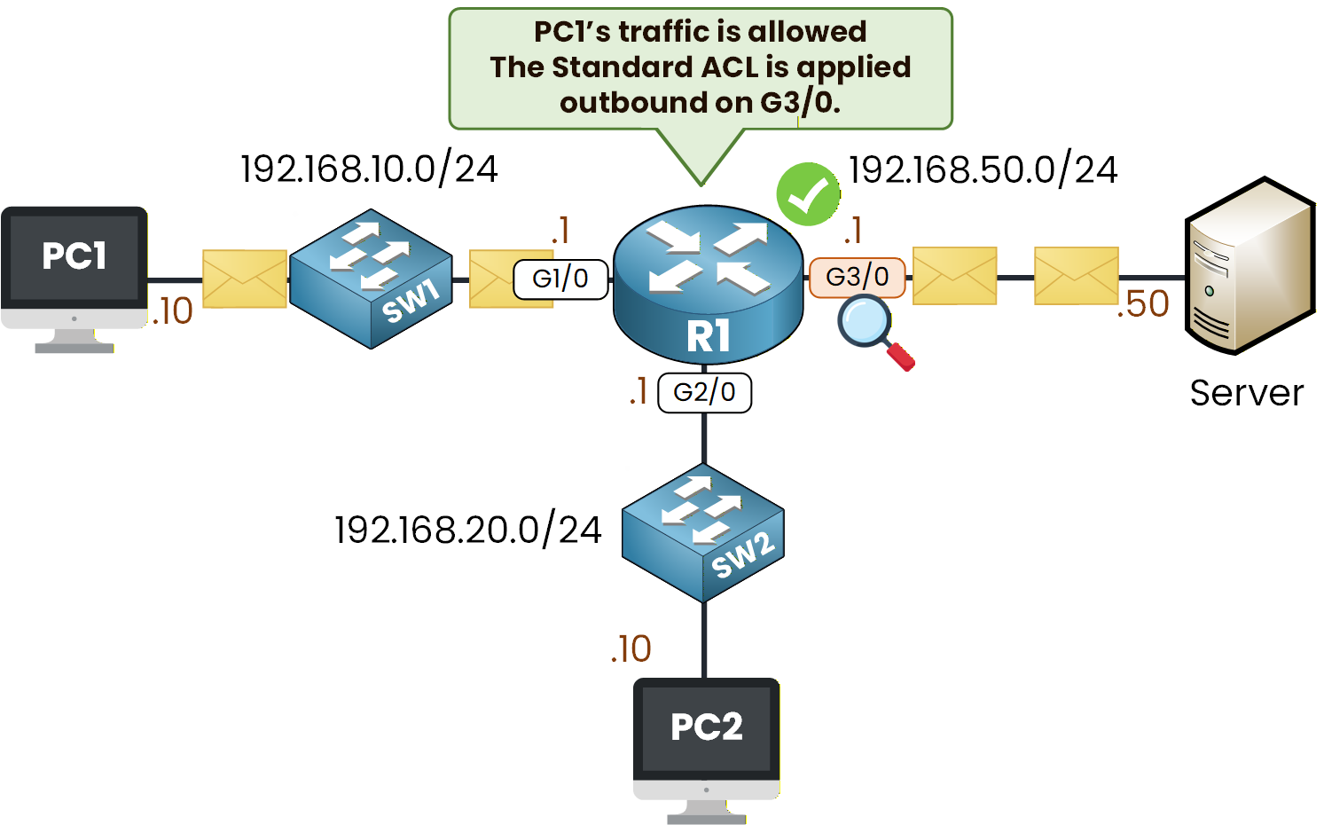
Figure 4 - Outbound ACL Filtering Behavior on PC1 Traffic
From PC2, try the same command:
C:\> ping 192.168.50.50

Pinging 192.168.50.50 with 32 bytes of data:

Reply from 192.168.20.1: Destination host unreachable.
This one should be blocked.
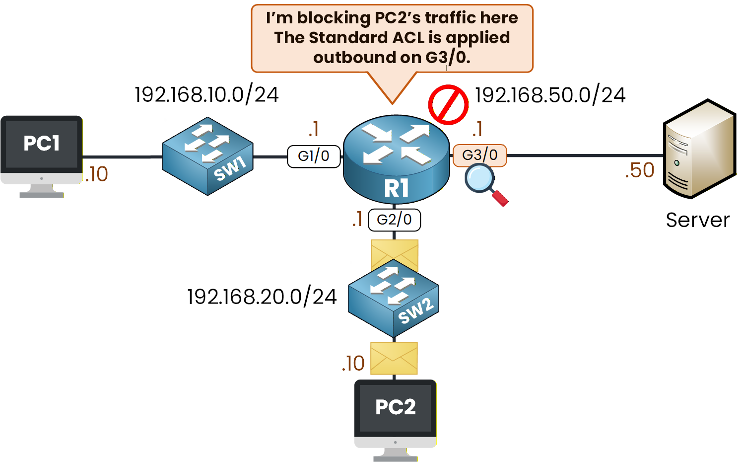
Figure 5 - Outbound ACL Filtering Behavior on PC2 Traffic
If you observe these two behaviors, your Standard ACL is correctly configured and applied.
Now, let's move on to Step 2.Answer the question below
On which interface is the ACL applied?
Before starting this step, remove the Standard ACL from the interface.
If it stays applied on R1, it will continue blocking traffic toward the Server and you won’t see the correct behavior for the Extended ACL.Detach the ACL from interface g3/0:
R1(config)# interface g3/0
R1(config-if)# no ip access-group 10 out
R1(config-if)# exit
The interface is now clean and ready for the next configuration.
Configure the Extended ACL
In this step, you will create and apply an Extended ACL.
Compared to Standard ACLs, an Extended ACL gives you much more control: you can match the source address, the destination address, the protocol, and even specific port numbers.Figure 6 - ACL Configuration Lab Topology
Your objective here is simple:
Block HTTPS traffic from PC2 to the Server.
Allow all other traffic so both PCs can still reach the Server.
Create the Extended ACL
We now create an Extended ACL on R1.
This ACL must deny HTTPS from PC2 and leave all remaining traffic untouched.R1(config)# ip access-list ? extended Extended Access List standard Standard Access List R1(config)# ip access-list extended ? <100-199> Extended IP access-list number WORD name R1(config)# ip access-list extended 100Select TCP as the protocol:
R1(config-ext-nacl)# deny ?
  ahp    Authentication Header Protocol
  eigrp  Cisco's EIGRP routing protocol
  esp    Encapsulation Security Payload
  gre    Cisco's GRE tunneling
  icmp   Internet Control Message Protocol
  ip     Any Internet Protocol
  ospf   OSPF routing protocol
  tcp    Transmission Control Protocol
  udp    User Datagram Protocol
Specify PC2 as the source.
For simplicity, we use host 192.168.20.10, but we could also use a wildcard if needed.R1(config-ext-nacl)# deny tcp host 192.168.20.10 ? A.B.C.D Destination address any Any destination host eq Match only packets on a given port number gt Match only packets with a greater port number host A single destination host lt Match only packets with a lower port number neq Match only packets not on a given port number range Match only packets in the range of port numbersSpecify the Server as the destination and apply the HTTPS port filter:
R1(config-ext-nacl)# deny tcp host 192.168.20.10 host 192.168.50.50 eq 443Allow all remaining traffic:
R1(config-ext-nacl)# permit ip any any
R1(config-ext-nacl)# exit
The last line is important.
Without it, the router would block all remaining traffic because every ACL ends with an implicit deny all.
With permit ip any any, only HTTPS from PC2 is filtered and all other protocols continue working.Apply the Extended ACL
Extended ACLs should be applied as close to the source as possible so the router drops unwanted traffic immediately.
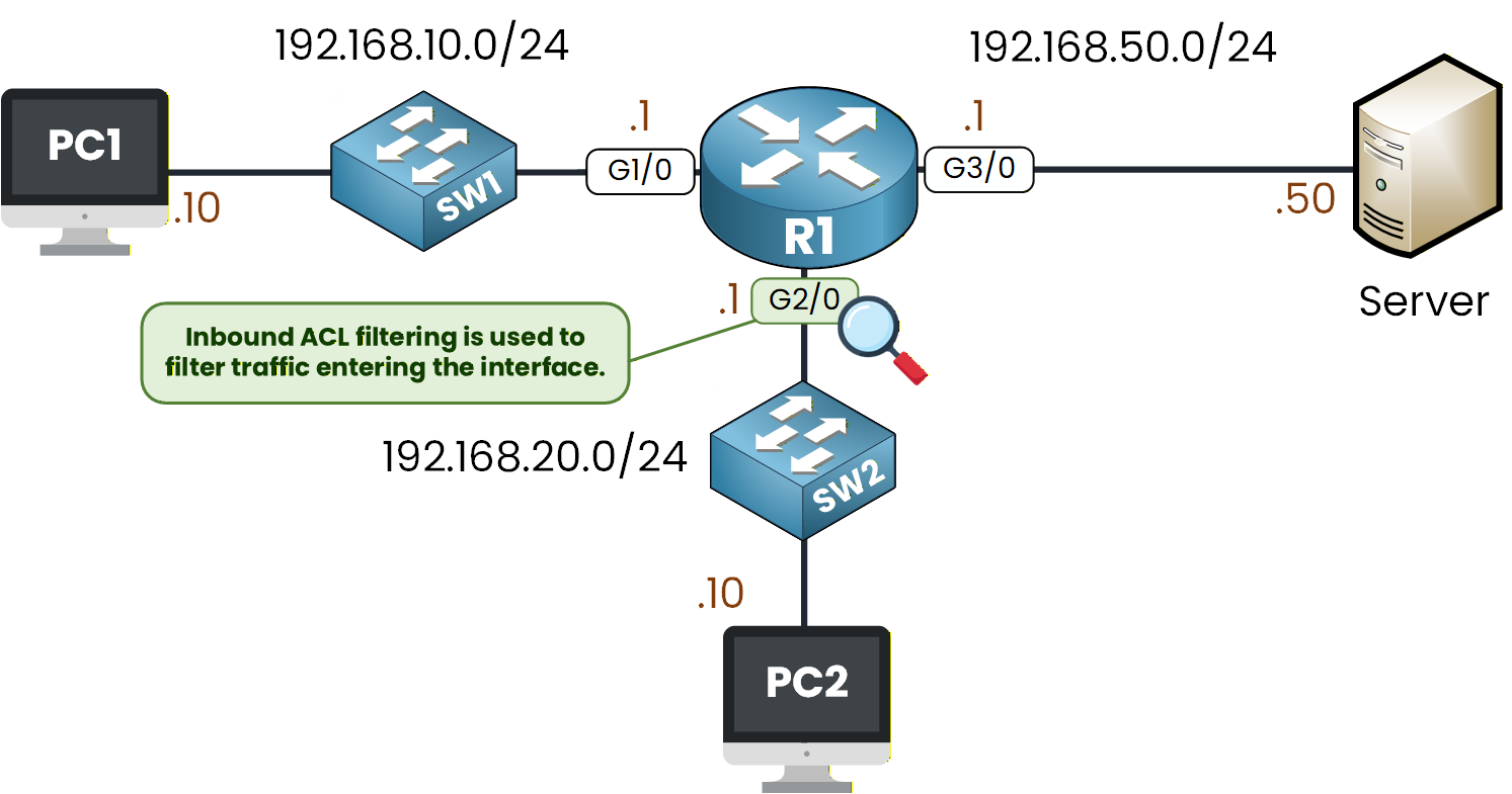
Figure 7 - Inbound ACL Filtering Behavior
In this topology:
PC2 sends its traffic into R1 through interface g2/0
Only PC2’s HTTPS traffic needs to be filtered
Apply the ACL inbound on interface g2/0:
R1(config)# interface g2/0
R1(config-if)# ip access-group 100 in
R1(config-if)# exit
The ACL is now active.
Verify the Extended ACL Is Applied
Before testing anything, confirm that your ACL is correctly attached to the interface.
R1# show ip int g2/0
GigabitEthernet2/0 is up, line protocol is up (connected)
  Internet address is 192.168.20.1/24
  Broadcast address is 255.255.255.255
  Address determined by setup command
  MTU is 1500 bytes
  Helper address is not set
  Directed broadcast forwarding is disabled
  Outgoing access list is not set
  Inbound  access list is 100
You should see: Inbound access list is 100.
If you do not see it, review your interface configuration and reapply the ACL.
Test the Extended ACL
Let’s verify that your configuration works exactly as intended.
Test HTTPS from PC1
For the HTTPS test, we assume you have a web client on PC1 able to reach the Server on https://192.168.50.50.
Since the Extended ACL only blocks PC2, the request from PC1 should succeed and the Server page should load without any issue.This confirms that HTTPS is allowed for PC1.
Test HTTPS from PC2
Now do the same thing from PC2: try to reach https://192.168.50.50 from a web client on PC2.
This time the request must not succeed. The page will fail to load, indicating that HTTPS traffic from PC2 has been blocked by the ACL.To confirm that only HTTPS is being filtered, run a ping from both PCs:
C:\> ping 192.168.50.50

Pinging 192.168.50.50 with 32 bytes of data:

Reply from 192.168.50.50: bytes=32 time<1ms TTL=127
Reply from 192.168.50.50: bytes=32 time<1ms TTL=127
Both PCs should receive replies, since ICMP is allowed by the final
permit ip any any.If everything matches what you observe, your Extended ACL is working correctly.
Answer the question below
On which interface is the Extended ACL applied?
Before starting this step, remove the Extended ACL from the interface.
If it remains applied, it will continue filtering traffic and interfere with the Named ACL you are about to configure.Detach the ACL from the inbound interface:
R1# conf t
Enter configuration commands, one per line.  End with CNTL/Z.
R1(config)# interface g2/0
R1(config-if)# no ip access-group 100 in
R1(config-if)# exit
Your interface is now ready for the next configuration.
Configure the Named ACL
In this step, you will configure a Named Extended ACL.
Figure 8 - ACL Configuration Lab Topology
Your objective here is simple:
PC2 must not be able to use ICMP toward the Server
PC2 must not be able to use HTTPS toward the Server
All other traffic must remain allowed
This gives you experience combining multiple filtering conditions inside a single ACL.
Create the Named ACL
Let’s define the Named ACL on R1.
It will block ICMP echo requests from PC2, block HTTPS from PC2, and allow all other traffic.R1(config)# ip access-list extended FILTER-PC2 R1(config-ext-nacl)# deny icmp host 192.168.20.10 host 192.168.50.50 R1(config-ext-nacl)# deny tcp host 192.168.20.10 host 192.168.50.50 eq 443 R1(config-ext-nacl)# permit ip any any R1(config-ext-nacl)# exitThe first rule blocks ICMP from PC2 to the Server.
The second rule blocks HTTPS traffic from PC2.
The last rule allows all remaining traffic.Apply the Named ACL
Extended ACLs should be placed close to the source.
Since PC2 sends its traffic into R1 through interface g2/0, apply the ACL inbound on that interface:R1(config)# interface g2/0 R1(config-if)# ip access-group FILTER-PC2 in R1(config-if)# endVerify the Named ACL Is Applied
Use the following command to confirm that the ACL is attached correctly:
R1# show ip interface g2/0
GigabitEthernet2/0 is up, line protocol is up (connected)
  Internet address is 192.168.20.1/24
  Broadcast address is 255.255.255.255
  Address determined by setup command
  MTU is 1500 bytes
  Helper address is not set
  Directed broadcast forwarding is disabled
  Outgoing  access list is not set
  Inbound access list is FILTER-PC2
You should see: Inbound access list is FILTER-PC2.
If not, review the interface configuration.
Test the Named ACL
Now verify that each rule behaves as intended.
Test ICMP from PC2
PC2 should not be able to use ICMP toward the Server.
C:\> ping 192.168.50.50

Pinging 192.168.50.50 with 32 bytes of data:

Reply from 192.168.10.1: Destination host unreachable.
Test HTTPS from PC2
For the HTTPS test, we assume you try to reach https://192.168.50.50 from a web client on PC2.
The page should not load, confirming that HTTPS from PC2 is blocked by the Named ACL.Test other traffic from PC1
Other traffic from PC1 should still work normally, since the Named ACL is applied only to interface g2/0 and filters only PC2.
Example:
C:\> ping 192.168.50.50

Pinging 192.168.50.50 with 32 bytes of data:

Reply from 192.168.50.50: bytes=32 time<1ms TTL=127
If everything you observe matches these results, the Named ACL is behaving exactly as expected, and you have successfully completed this final step of the lab.
Answer the question below
What is the name of the ACL?
Congratulations, you just finished the ACL configuration lab!
In this lab, you practiced the three ACL formats required for the CCNA:Standard ACL
Extended ACL
Named ACL
You created filters, applied them to the correct interfaces, verified the configuration, and tested the results directly from the PCs.
Before closing this lab, make sure you are comfortable creating ACLs, applying them on an interface, verifying them, and testing how they affect traffic.
Most Important Commands
These are the core ACL commands you’ll use both in the CCNA exam and in real network configurations.
R1(config)# ip access-list standard <number | name>
R1(config)# ip access-list extended <number | name>

R1(config-std-nacl)# permit <conditions>
R1(config-std-nacl)# deny <conditions>

R1(config)# interface <id>
R1(config-if)# ip access-group <ACL> in
R1(config-if)# ip access-group <ACL> out

R1# show ip access-lists
R1# show ip interface <id>
Answer the question below
Click 'Complete' to continue