Spine and Leaf Architecture Cisco

1. Introduction

Today, the Spine and Leaf Architecture Cisco developed is the foundation of most modern data center designs.

Diagram showing the spine and leaf architecture Cisco with spine switches connected to leaf switches and servers.

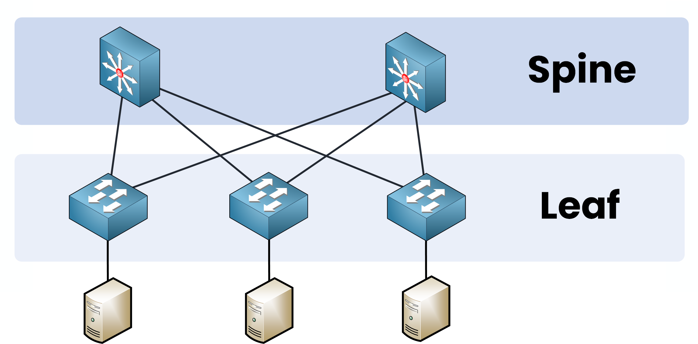
Figure 1 – Spine and Leaf Architecture

But how did it become so popular?

To really understand this, let’s take a step back together and revisit the traditional Three-Tier Architecture, the design that shaped network infrastructures for years when traffic patterns were very different from today.

2. Traditional Three-Tier Architecture

Back in the early 2000s, networks were built for a different world.

At that time:

  • Data centers had fewer servers.

  • Applications were simple, mostly client-server based.

  • Latency wasn’t a critical issue.

  • Bandwidth requirements were modest.

The traditional Three-Tier Architecture was perfect for these needs.

Diagram of traditional Three-Tier Architecture with Core, Distribution, and Access layers showing Layer 2 and Layer 3 separation.

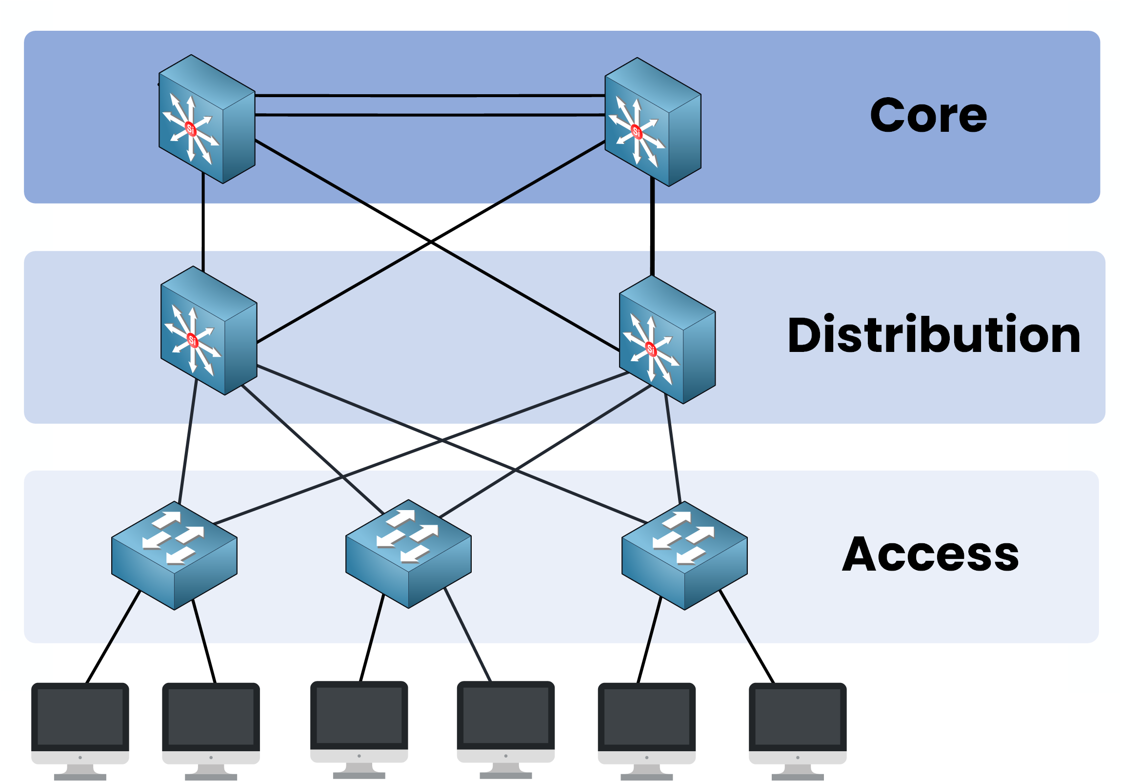
Figure 2 – Traditional Three-Tier Architecture

In this design:

  • Access to Distribution = Layer 2 switching

  • Distribution to Core = Layer 3 routing

To prevent loops at Layer 2, the network depends on the Spanning Tree Protocol (STP).

North-South Traffic

Originally, networks were optimized for North-South traffic, traffic flowing between clients and servers, typically moving in and out of the data center.

Diagram showing North-South traffic flow in a traditional Three-Tier Architecture with Core, Distribution, and Access layers.

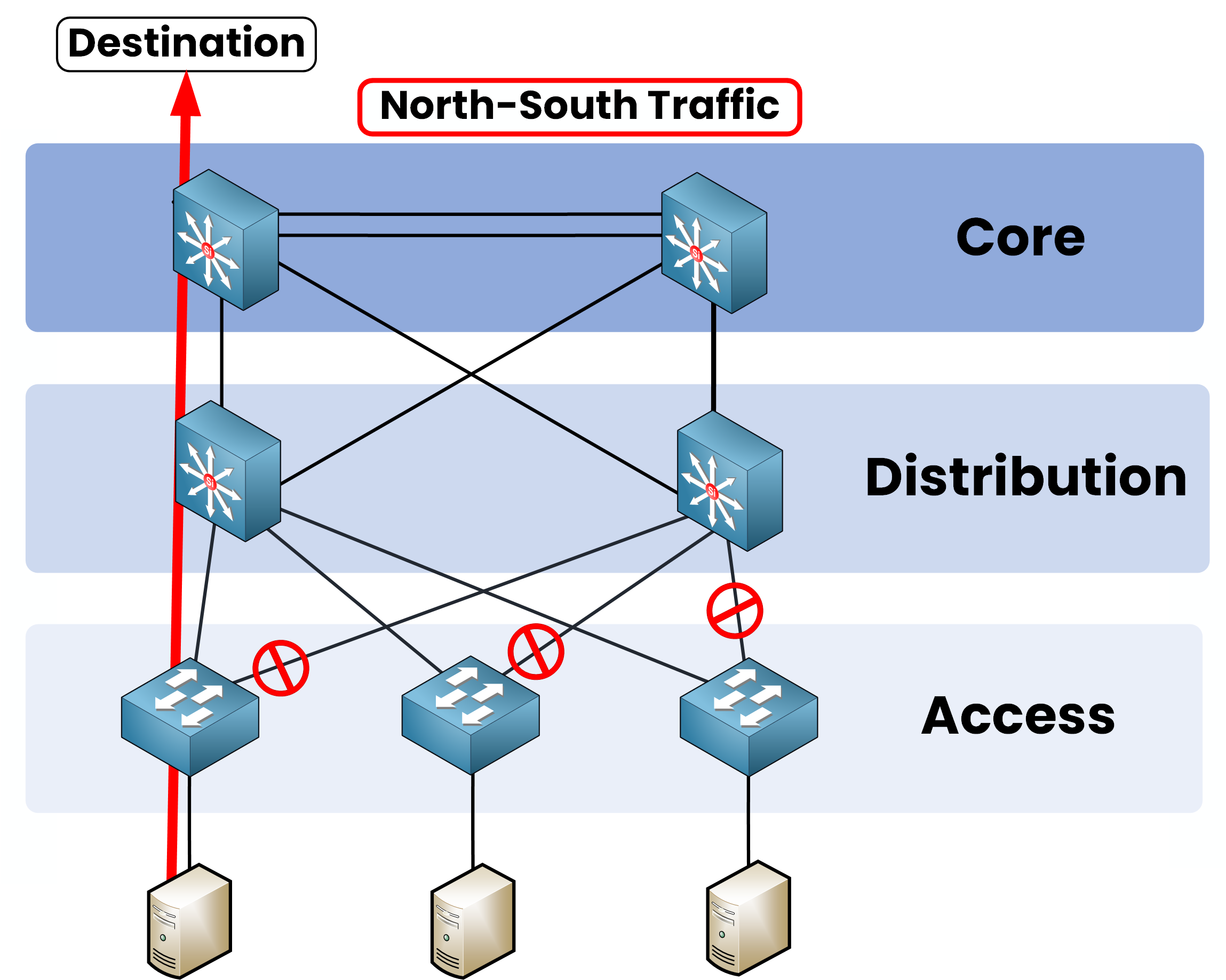
Figure 3 – North–South Traffic Flow

In that scenario:

  • Latency wasn’t critical.

  • Some blocked links by STP were acceptable.

  • Bandwidth demand was low.

East-West Traffic

However, as data center traffic patterns evolved, a new type of traffic emerged:

  • East-West traffic, server-to-server communication inside the data center became dominant.

Diagram showing East-West traffic flow in a traditional Three-Tier Architecture with server-to-server communication.

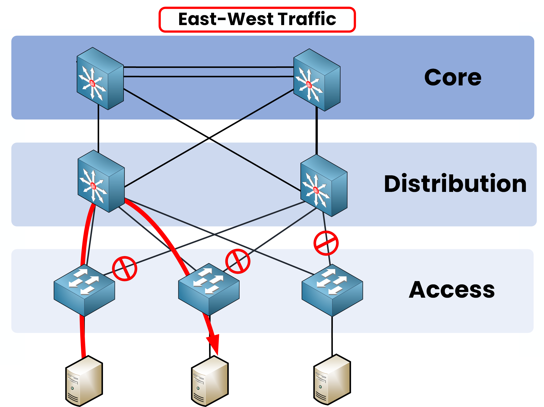
Figure 4 – East–West Traffic Limitation

In this new environment:

  • STP blocks redundant links, preventing full bandwidth usage.

  • Bandwidth is wasted, and servers can’t leverage all available paths.

  • Multiple hops across the Access, Distribution, and Core layers increased latency.

Initially, the three-tier design worked fine but a major bottleneck occurred as East-West traffic exploded!

3. Improvements with vPC

To solve this, Cisco introduced vPC (Virtual Port-Channel) and it was a real step forward.

With vPC:

  • Two active uplinks from each Access switch to the Distribution layer.

  • Better bandwidth utilization.

Three-Tier Architecture Cisco diagram with vPC enabled, showing two active uplinks from Access to Distribution to overcome STP limitations.

Figure 5 – Enhanced Layer 2 with vPC


But vPC also has a limitation:

Three-Tier Architecture Cisco diagram showing vPC limitation with only two active uplinks per Access switch and extra links blocked.

Figure 6 – vPC Limitation with Extra Uplink

vPC is limited to two active uplinks between Access and Distribution switches.

If you try to connect to more than two distribution switches,
STP blocks the extra links and they remain unused!

This quickly becomes a bottleneck as data centre traffic grows.

4. Transition to Spine and Leaf Architecture

At this point, network engineers asked:

“What if we moved to full Layer 3 between Access and Core?”

No more Spanning Tree, no more blocked links, every path could be active.

This idea led to the Spine and Leaf Architecture Cisco promotes as the ideal solution for high-performance data centers.

Diagram of Spine and Leaf Architecture Cisco showing full Layer 3 connections between spine and leaf switches.

Figure 7 – Spine and Leaf Architecture (Layer 3 Everywhere)

In this design:

  • All links are active

  • All connections are Layer 3.

  • No Spanning Tree needed.

5. Evolution of Data Centers

At the same time, virtualisation was booming (as you know, VMware).

With virtualisation came the need for:

Diagram showing East-West traffic in a spine and leaf architecture Cisco with server-to-server communication.

Figure 8 – East–West Traffic in a Spine–Leaf Architecture

Traditional designs couldn’t handle this surge effectively, but Cisco's spine and leaf architecture was specifically designed to meet the demands of the new data center.

Let's dive together into the 2 layers of this architecture !

6. Spine Layer

Let's start with the spine layer, the true core of the spine and leaf architecture.

🟢 Key points you need to remember:

  • Each spine switch connects to every leaf switch in the network.

  • Spines are never connected to each other, no direct spine-to-spine links.

  • All paths between leaves and spines are active simultaneously, ensuring maximum bandwidth and redundancy.

Diagram showing the spine layer in a spine and leaf architecture Cisco with spine switches connected to leaf switches.

Figure 9 – Spine Layer

The more spine switches you add, the more you increase your network’s overall capacity and performance.

7. Leaf Layer

Now let's move on to the leaf layer, where all your end devices connect, typically servers or storage systems.

🟢 Key points to focus on:

  • Every leaf switch is connected to every spine switch, it's a full mesh between leaf and spines.

  • Leaf switches are never directly connected to each other, communication always goes through a spine.

Diagram showing the leaf layer in a spine and leaf architecture Cisco with leaf switches connected to spine switches.

Figure 10 – Leaf Layer

When two devices communicate, the traffic flow always takes exactly two hops:

Device → Leaf → Spine → Leaf → Device

8. Conclusion

Congratulations! 🎉 You’ve now mastered the key principles of the spine and leaf architecture Cisco designed, the foundation behind modern data centers.

Let’s quickly review what you’ve learned:

🟢 Traditional Three-Tier Limitations:

  • Designed for older traffic patterns (North-South).

  • Spanning Tree Protocol (STP) blocked redundant links.

  • High latency and poor bandwidth utilization for East-West traffic.

🟢 The Rise of Spine and Leaf:

  • Solved the bottlenecks of the Three-Tier model.

  • Full Layer 3 connectivity, no more STP.

  • All paths are active, maximizing bandwidth and reducing latency.

🟢 Spine Layer:

  • Acts as the network’s core.

  • Every spine connects to every leaf, no spine-to-spine connections.

  • Scaling is simple: add more spine switches, and your network capacity grows.

🟢 Leaf Layer:

  • Connects your servers and end devices.

  • Each leaf connects