The Spanning Tree Protocol (STP) is a Layer 2 protocol designed to prevent switching loops in Ethernet networks.
It ensures that even if multiple physical paths exist between switches, only one logical path is active at a time.Why STP Is Needed
In modern Ethernet networks, reliability often relies on link redundancy.
Network engineers commonly connect switches using multiple links so that if one cable fails, another can immediately take over.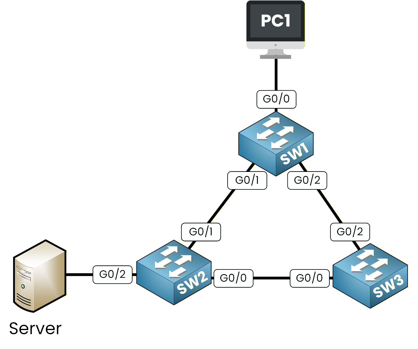
Figure 1 – Basic Redundant Network Topology
At first, this design seems ideal. For example, if PC1 needs to send traffic to server, two possible paths exist:
One through PC1 → SW1 → SW2 → Server
Another through PC1 → SW1 → SW3 → SW2 → Server
However, having multiple paths to the same destination can be dangerous because it may create switching loops. A switching loop occurs when Ethernet frames circulate endlessly within the network, consuming bandwidth and potentially causing the switches to crash.
Let's examine how this problem happens in a simple redundant topology before STP is enabled.Answer the question below
Step 1 – PC1 Sends an ARP Request
Imagine you're on PC1 and want to communicate with the server.
Since PC1 doesn't yet know the server's MAC address, it sends an ARP broadcast asking, “Who has this IP address?”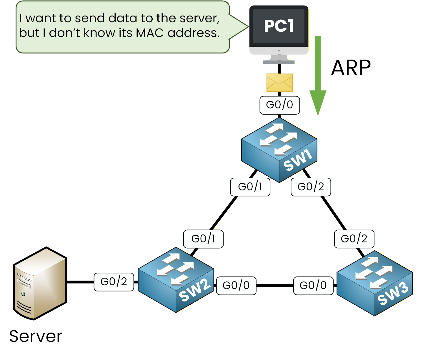
Figure 2 – PC1 Sends an ARP Request (Broadcast)
First, the broadcast ARP Request arrives at interface g0/0 of SW1.
Step 2 – SW1 Floods the Broadcast
The switch SW1 receives the ARP broadcast on G0/0 and floods it out of all other interfaces (G0/1 and G0/2).
At this stage, the frame is duplicated and sent toward both SW2 and SW3.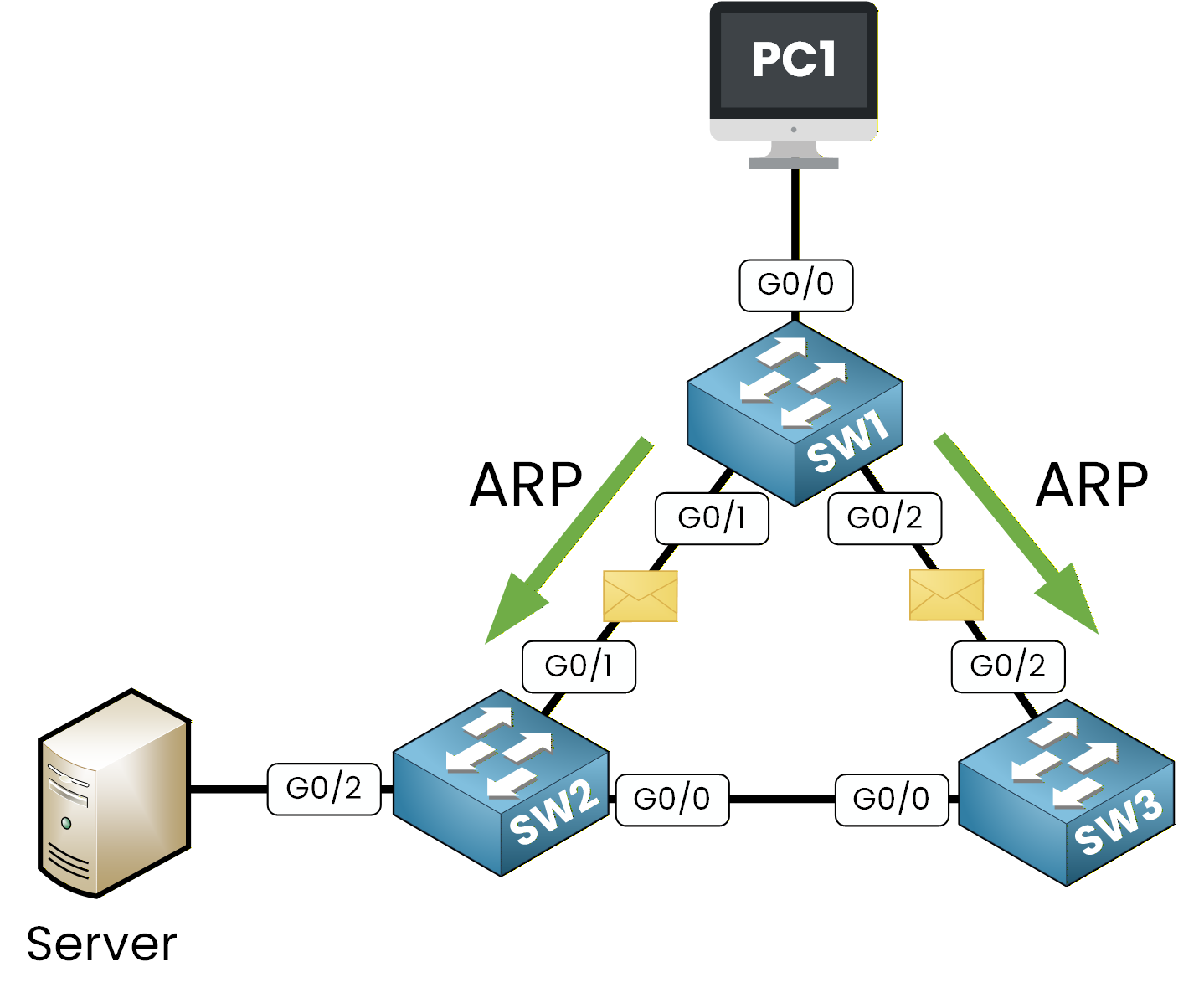
Figure 3 – SW1 Floods the ARP Broadcast
At this point, a single ARP request becomes two identical ARP frames, one sent toward SW2 and the other toward SW3. This is where the issue starts. Let's see what happens when these ARP requests reach SW2 and SW3.
Step 3 – SW2 and SW3 Flood the Broadcast Again
SW2 and SW3 receive the ARP broadcast from SW1.
Since they still don't know the server's MAC address, they forward the frame out of all ports except the one where it was received.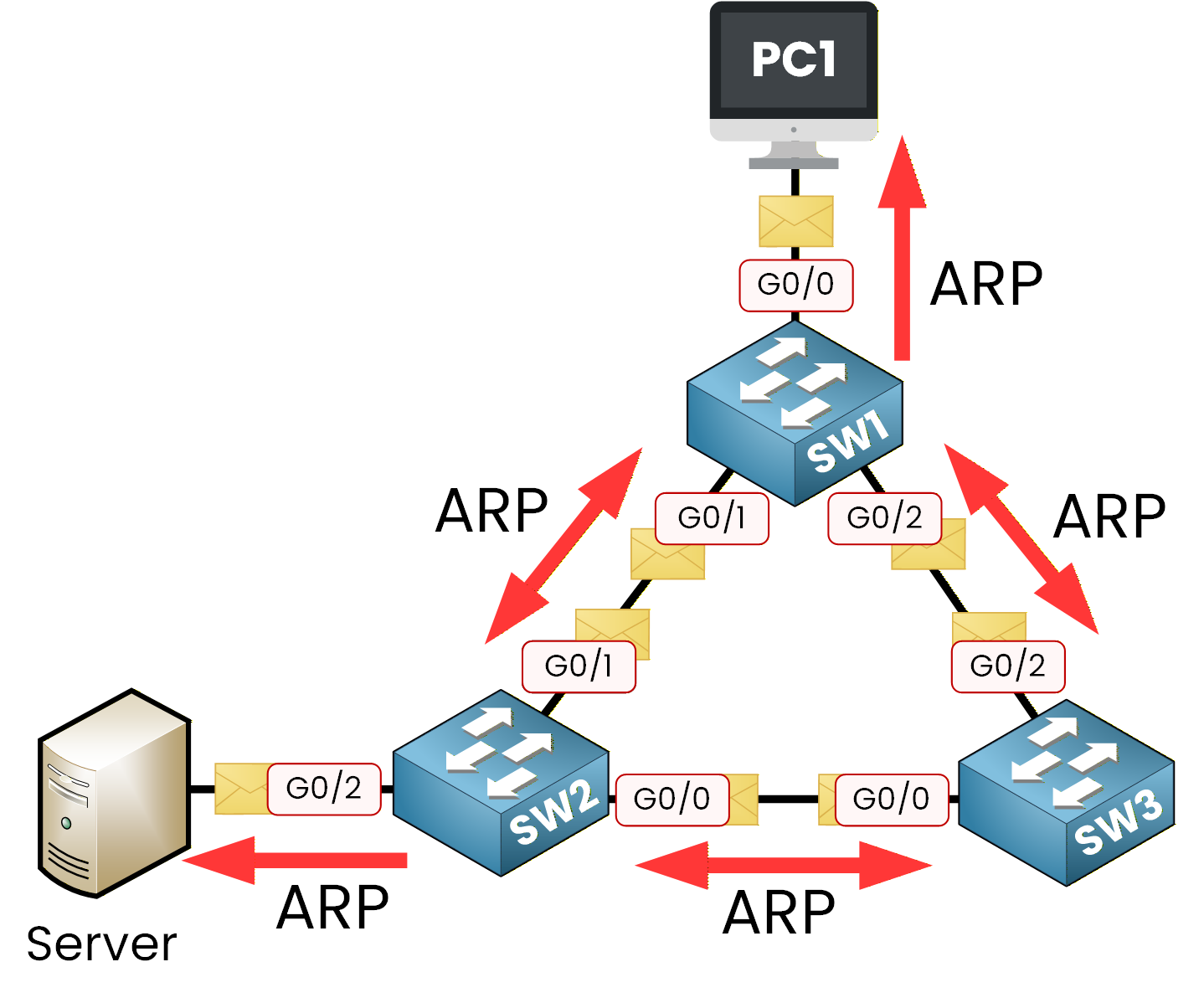
Figure 4 – SW2 and SW3 Flood the Broadcast Again (Loop Begins)
SW2 sends the ARP request to both the server and SW3, while SW3 sends it to SW2 and back to SW1.
Then, SW1 receives new copies of the same ARP request and floods them again toward PC1 and SW2.
At this point, every switch keeps forwarding new ARP broadcasts, and the number of frames grows exponentially.40 % Complete: you’re making great progress
Ready to pass your CCNA exam?