Router on a Stick (ROAS) is one of the three methods of Inter-VLAN Routing that we introduced earlier in the InterVLAN Routing course.
To quickly recap, the three approaches are:Legacy Inter-VLAN Routing – using multiple physical router interfaces (rarely used today).
Router-on-a-Stick (ROAS) – using subinterfaces on a single router interface.
Layer 3 Switch (SVIs) – the modern and scalable solution.
In this lesson, we will focus on Router on a Stick, which allows a network administrator to route packets between multiple VLANs using a single router interface divided into subinterfaces.
This is the reference topology we’ll use throughout the course:

Figure 1 – Router on a Stick Topology
PC1 in VLAN 10 (192.168.1.0/24)
Server in VLAN 20 (192.168.2.0/24)
By configuring Router on a Stick, we enable communication between these two VLANs.
The first concept you need to understand for this method is the subinterface.Answer the question below
A subinterface is a virtual interface created under a single physical router interface.
Each subinterface is associated with a specific VLAN ID using 802.1Q encapsulation.
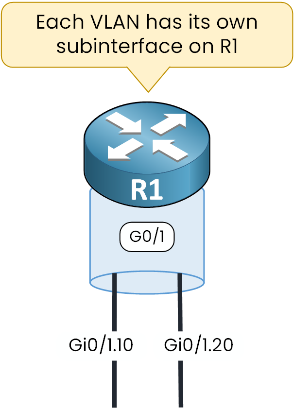
Figure 2 – Subinterfaces on R1
In our example, the physical interface Gi0/1 is divided into two subinterfaces:
Gi0/1.10 → VLAN 10
Gi0/1.20 → VLAN 20
Each VLAN gets its own subinterface, which serves as the default gateway for all devices inside that VLAN.
Because we use one physical interface to support multiple VLANs through subinterfaces, this design is called Router on a Stick (ROAS).
Answer the question below
Which protocol tags VLANs on subinterfaces?

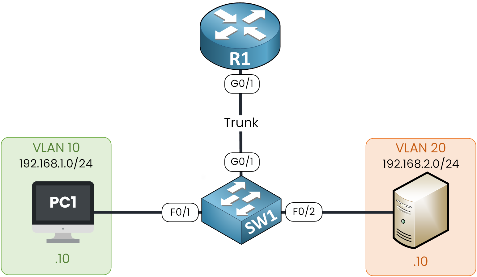
Figure 3 – Router on a Stick Topology
Step 1 — Switch: Define VLANs & Assign Access Ports
First, we need to create the VLANs for the Client (VLAN 10) and the Server (VLAN 20).
SW1# configure terminal Enter configuration commands, one per line. End with CNTL/Z. SW1(config)# vlan 10 SW1(config-vlan)# name client SW1(config-vlan)# exit SW1(config)# vlan 20 SW1(config-vlan)# name server SW1(config-vlan)# exitOnce the VLANs are created, we assign the access ports to the right VLANs.
SW1(config)# interface fastEthernet 0/1 SW1(config-if)# switchport mode access SW1(config-if)# switchport access vlan 10 SW1(config-if)# exit SW1(config)# interface fastEthernet 0/2 SW1(config-if)# switchport mode access SW1(config-if)# switchport access vlan 20 SW1(config-if)# exitStep 2 — Switch: Configure the 802.1Q Trunk to the Router
Now, we need to prepare the connection between the switch and the router.
Since the link must carry multiple VLANs, we convert interface Gi0/1 into a trunk port.SW1(config)# interface gigabitEthernet 0/1 SW1(config-if)# no shutdown %LINK-5-CHANGED: Interface GigabitEthernet0/1, changed state to up %LINEPROTO-5-UPDOWN: Line protocol on Interface GigabitEthernet0/1, changed state to up SW1(config-if)# switchport mode trunk SW1(config-if)# switchport trunk ? allowed Set allowed VLAN characteristics when interface is in trunking mode native Set trunking native characteristics when interface is in trunking mode SW1(config-if)# switchport trunk allowed vlan 10,20 SW1(config-if)# endHere, we allow only VLAN 10 and VLAN 20 on the trunk to restrict unnecessary traffic.
Note: In real networks, it’s good practice to use a dedicated native VLAN that is not assigned to users. For our lab, leaving the default is fine.
Step 3 — Router: Bring Up the Physical Interface
Next, we move to the router.
We start by enabling the physical interface Gi0/1 , this is the “stick” where we will create subinterfaces.R1# configure terminal Enter configuration commands, one per line. End with CNTL/Z. R1(config)# interface gigabitEthernet 0/1 R1(config-if)# no shutdown %LINK-5-CHANGED: Interface GigabitEthernet0/1, changed state to up %LINEPROTO-5-UPDOWN: Line protocol on Interface GigabitEthernet0/1, changed state to up R1(config-if)# endLet’s quickly verify that the interface is up:
R1# show ip int brief Interface IP-Address OK? Method Status Protocol GigabitEthernet0/0 unassigned YES unset administratively down down GigabitEthernet0/1 unassigned YES unset up up GigabitEthernet0/2 unassigned YES unset administratively down downStep 4 — Router: Create Subinterfaces (One per VLAN)
Now that our physical interface is ready, we can create one subinterface for each VLAN.
This step is quite straightforward, so let’s walk through it together.
Figure 4 – Router on a Stick Subinterface Configuration
We start with the physical interface Gi0/1 and add labels to create the subinterfaces:
Gi0/1.10 → VLAN 10
Gi0/1.20 → VLAN 20
The subinterface number does not have to match the VLAN ID, but in practice we usually make them the same. This makes the configuration much easier to read and maintain.
Next, we bind each subinterface to a VLAN using 802.1Q encapsulation, and we assign an IP address that will serve as the default gateway for that VLAN.
Here is the configuration:
R1(config)# interface gigabitEthernet 0/1.10 R1(config-subif)# encapsulation dot1Q 10 R1(config-subif)# ip address 192.168.1.1 255.255.255.0 R1(config-subif)# no shutdown %LINK-5-CHANGED: Interface GigabitEthernet0/1.10, changed state to up %LINEPROTO-5-UPDOWN: Line protocol on Interface GigabitEthernet0/1.10, changed state to up R1(config-subif)# exit R1(config)# interface gigabitEthernet 0/1.20 R1(config-subif)# encapsulation dot1Q 20 R1(config-subif)# ip address 192.168.2.1 255.255.255.0 R1(config-subif)# no shutdown %LINK-5-CHANGED: Interface GigabitEthernet0/1.20, changed state to up %LINEPROTO-5-UPDOWN: Line protocol on Interface GigabitEthernet0/1.20, changed state to up R1(config-subif)# endSubinterface Checklist
To configure a subinterface, we always follow the same 4 steps:
Create the subinterface (
Gi0/1.x)Apply encapsulation (
encapsulation dot1Q)Set the IP address (gateway for the VLAN)
Enable it (
no shutdown)
Verification
Now that the subinterfaces are configured, let’s check that everything is working as expected.
R1# show ip int brief Interface IP-Address OK? Method Status Protocol GigabitEthernet0/0 unassigned YES unset administratively down down GigabitEthernet0/1 unassigned YES unset up up GigabitEthernet0/1.10 192.168.1.1 YES manual up up GigabitEthernet0/1.20 192.168.2.1 YES manual up up GigabitEthernet0/2 unassigned YES unset administratively down downThe physical interface Gi0/1 has no IP address. This is normal in Router on a Stick, because only the subinterfaces handle IP routing.
Both subinterfaces Gi0/1.10 and Gi0/1.20 are up/up with their correct IP addresses.
This confirms that our subinterfaces are active and ready.
Next, let’s look at the routing table:
R1# show ip route Codes: L - local, C - connected, S - static, R - RIP, M - mobile, B - BGP D - EIGRP, EX - EIGRP external, O - OSPF, IA - OSPF inter area N1 - OSPF NSSA external type 1, N2 - OSPF NSSA external type 2 E1 - OSPF external type 1, E2 - OSPF external type 2, E - EGP i - IS-IS, L1 - IS-IS level-1, L2 - IS-IS level-2, ia - IS-IS inter area * - candidate default, U - per-user static route, o - ODR P - periodic downloaded static route Gateway of last resort is not set 192.168.1.0/24 is variably subnetted, 2 subnets, 2 masks C 192.168.1.0/24 is directly connected, GigabitEthernet0/1.10 L 192.168.1.1/32 is directly connected, GigabitEthernet0/1.10 192.168.2.0/24 is variably subnetted, 2 subnets, 2 masks C 192.168.2.0/24 is directly connected, GigabitEthernet0/1.20 L 192.168.2.1/32 is directly connected, GigabitEthernet0/1.20Here we see that R1 has learned both networks:
VLAN 10 → 192.168.1.0/24 via Gi0/1.10
VLAN 20 → 192.168.2.0/24 via Gi0/1.20
This means the router now knows how to route traffic between the two VLANs.
Answer the question below
On the router, which command binds a subinterface to VLAN 10 using 802.1Q encapsulation?
Let’s walk through InterVLAN routing step by step, together.
On PC1 (VLAN 10), we use the default gateway 192.168.1.1 (R1 subinterface Gi0/1.10):
PC1> ipconfig FastEthernet0 Connection:(default port) Connection-specific DNS Suffix..: Link-local IPv6 Address.........: FE80::2D0:D3FF:FE42:BD92 IPv6 Address....................: :: IPv4 Address....................: 192.168.1.10 Subnet Mask.....................: 255.255.255.0 Default Gateway.................: :: 192.168.1.1On the Server (VLAN 20), it’s the same idea: the default gateway is 192.168.2.1 (R1 subinterface Gi0/1.20).
Now, from PC1 we ping the server 192.168.2.10:
PC1> ping 192.168.2.10 Pinging 192.168.2.10 with 32 bytes of data: Reply from 192.168.2.10: bytes=32 time<1ms TTL=127 Reply from 192.168.2.10: bytes=32 time<1ms TTL=127 Reply from 192.168.2.10: bytes=32 time<1ms TTL=127 Reply from 192.168.2.10: bytes=32 time<1ms TTL=127 Ping statistics for 192.168.2.10: Packets: Sent = 4, Received = 4, Lost = 0 (0% loss), Approximate round trip times in milli-seconds: Minimum = 0ms, Maximum = 0ms, Average = 0msThe ping is successful, but it’s important to understand why.
PC1 sends a packet to 192.168.2.10. Since the destination IP address is outside its own network, the packet is forwarded to the default gateway 192.168.1.1, which is the router subinterface Gi0/1.10.
First, the switch receives the packet on F0/1 (assigned to VLAN 10) and forwards the frame towards the default gateway over the trunk link Gi0/1. On this trunk, the switch encapsulates the frame with the VLAN ID 10.

Figure 5 — PC1 to Default Gateway (R1 Subinterface)
The router R1 receives the packet on its physical interface Gi0/1.
Since the frame is tagged with VLAN 10, subinterface Gi0/1.10 processes it.R1 then makes a routing decision: the destination IP is 192.168.2.10, which belongs to the 192.168.2.0/24 network. That network is connected to subinterface Gi0/1.20, so the packet is routed there.
The router rewrites the Ethernet header, changes the VLAN tag from 10 to 20, and sends the packet back on the trunk.

Figure 6 — InterVLAN Routing Process
The switch receives this frame (now tagged VLAN 20) and forwards it to the server on F0/2.
As you can see, the InterVLAN Routing process combines:
Layer 2 technologies → VLANs and 802.1Q trunking
Layer 3 decisions → Router subinterfaces forwarding between VLANs
If we zoom out, the entire flow looks like this:

Figure 7 – Packet entire Flow with Router on a Stick
PC1 → SW1 (tag VLAN 10) → R1 Gi0/1.10 → R1 routes → R1 Gi0/1.20 (tag VLAN 20) → SW1 → Server
Router on a Stick Limitation
Now that you’ve seen the process, it’s important to highlight one major limitation.
All subinterfaces are configured on a single physical interface (Gi0/1).
This means all inter-VLAN traffic must pass through the same physical link.
Figure 8 – Router on a Stick bottleneck
If we add, for example, 50 VLANs, this single interface quickly becomes a bottleneck, because bandwidth is limited to that one link.To overcome this limitation, modern designs use Layer 3 switches with SVIs, allowing inter-VLAN routing to happen directly in the switch fabric. We will cover this method in the next course.
Answer the question below
During InterVLAN routing, after R1 receives a frame tagged with VLAN 10, what VLAN tag does it apply when forwarding the packet toward the server in VLAN 20?
Router on a Stick is a simple way to enable communication between VLANs using subinterfaces.
802.1Q subinterfaces on one router interface
Routing between VLANs with a single link
Limitation: all traffic on the same interface → bottleneck
Better option: Layer 3 switches with SVIs
This method works for small or lab networks, but it does not scale well.
In the next lesson, we will see how SVIs on Layer 3 switches solve these limits.Answer the question below
What is the main limitation of Router-on-a-Stick when several VLANs send traffic at the same time?
Router On a Stick
Router on a Stick is a classic method of inter-VLAN routing that uses subinterfaces on a single router interface to connect multiple VLANs. In this lesson, you will configure ROAS step by step and understand its benefits and limitations.