Network devices, like your home devices, need to share the same time across the network.
Routers and switches have internal clocks, but those clocks can drift. After days or weeks, different devices might show different times.
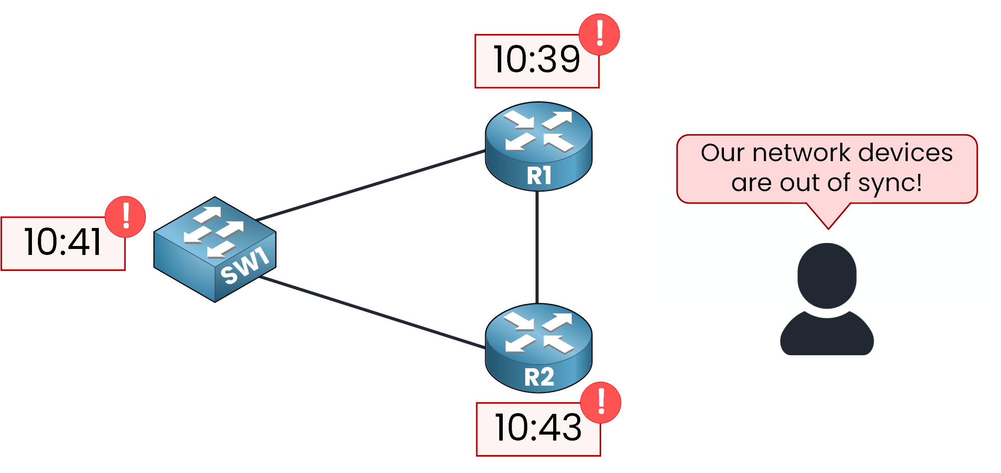
Figure 1 – Time out of sync before Network Time Protocol
Network Time Protocol (NTP) keeps all devices in sync with a common, accurate time source. With NTP in place, the whole network stays aligned.

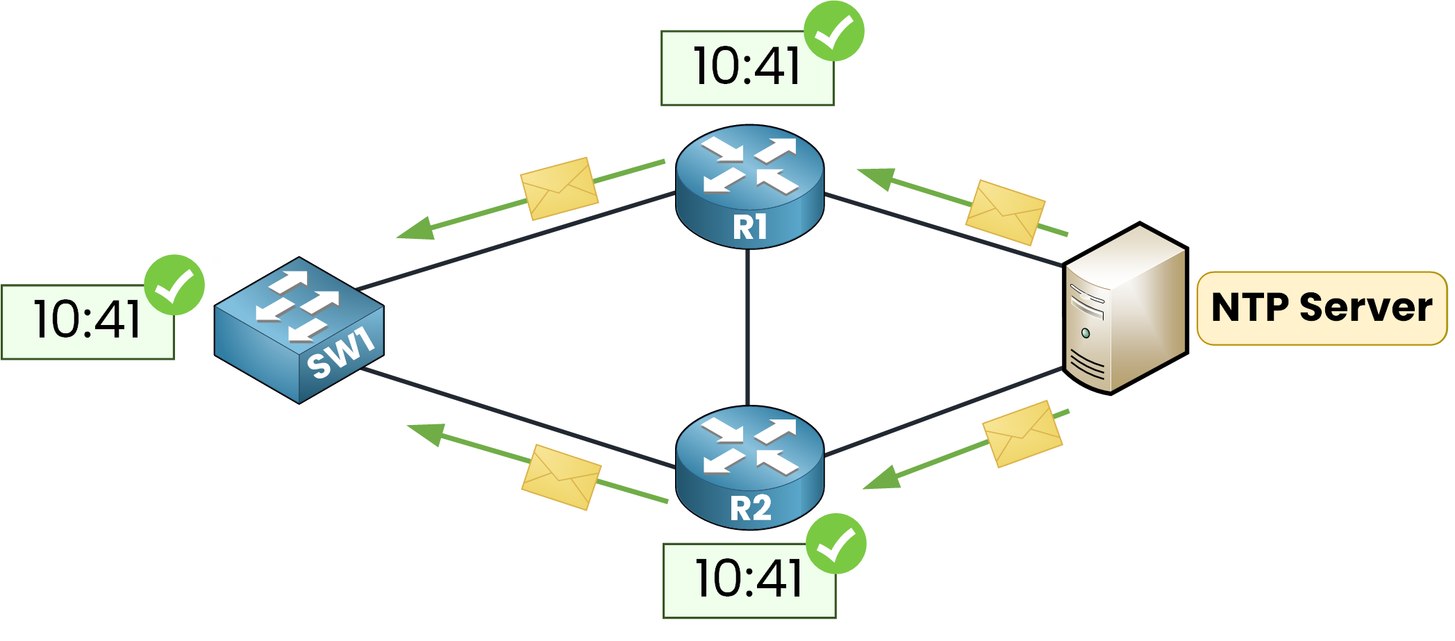
Figure 2 – Time synchronized with Network Time Protocol
The IETF standardized NTP in in RFC 5905, with NTPv4 being the current version. It’s widely used in enterprise networks to keep devices synchronized in time.
Why do we need synchronized time?
Log correlation (Syslog): Sync device timestamps. This helps accurately link events during troubleshooting or security issues.
Security & certificates: Many mechanisms rely on accurate time. For example, certificate validity and time-sensitive handshakes in IPsec/TLS depend on it.
Time-based policies & jobs:
Enforce time-based ACLs.
Run backups, scripts, and automations at the right times.
Meet auditing and compliance needs.
In short, synchronized clocks make the network easier to troubleshoot, more secure, and more reliable.
Answer the question below
NTP uses a simple Client–Server Model. In this model, an NTP Server is connected to a reliable time source and periodically sends timestamps to its clients. These timestamps are numeric values that represent the current time.
When the clients receive the information, they compare it with their own local clock and then adjust their time in small steps.
All exchanges are lightweight, and they use UDP port 123 for communication.
Reference Clock
An NTP Server doesn’t invent the time. It relies on a reference clock a highly accurate source such as a GPS receiver tied to atomic clocks, or a ground-based atomic/radio clock.

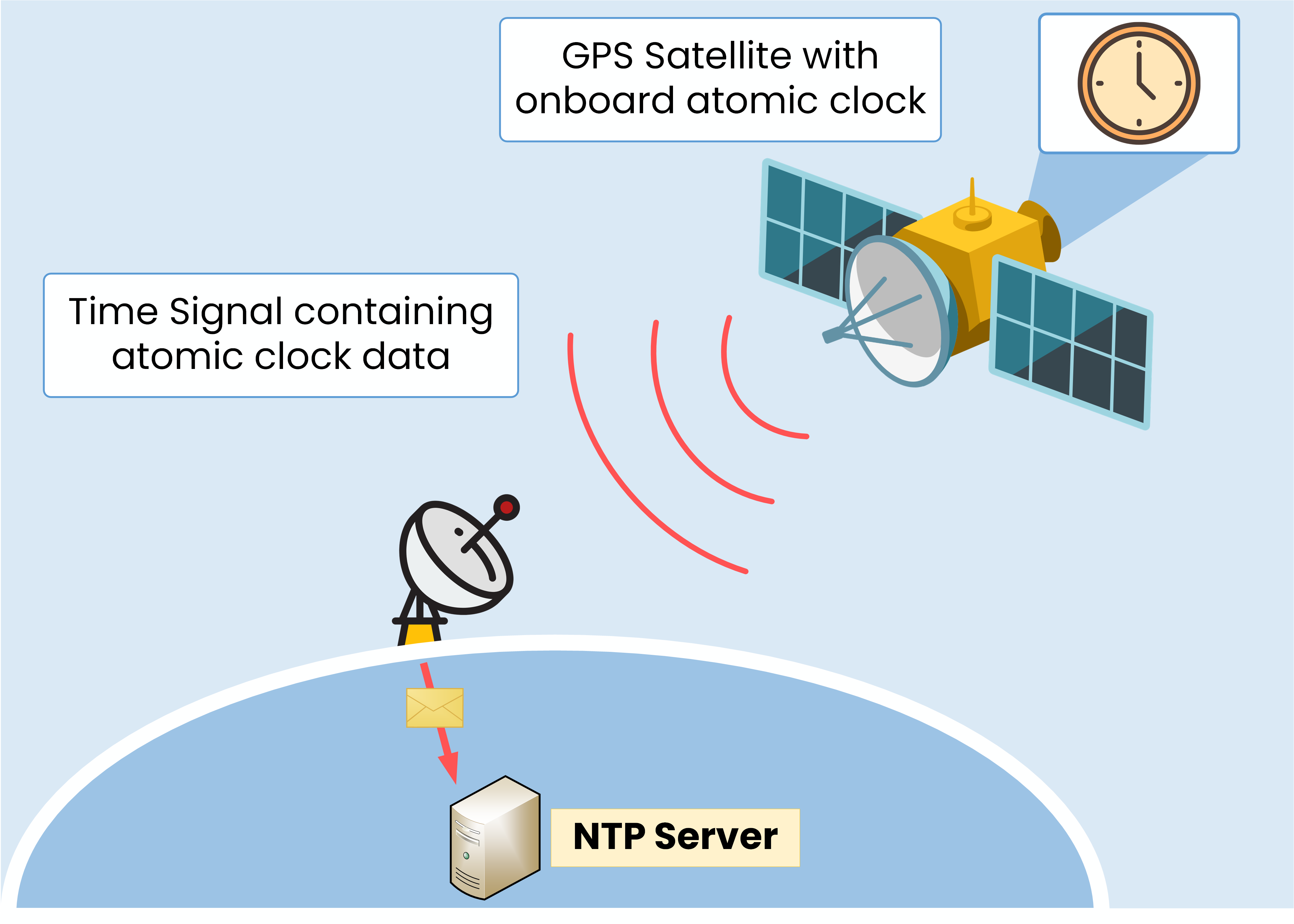
Figure 3 – Authoritative time source using onboard atomic clock
Traditionally, GPS satellites carry atomic clocks that provide extremely precise time. A ground antenna/dish receives the time signal, the NTP Server ingests those timestamps, and then distributes them to the rest of the network.
NTP Stratums
When using Network Time Protocol, remember that NTP networks are arranged in levels called stratums (from the Latin word for layer).
In NTP, a device’s stratum indicates how far it is from the most accurate time source, the reference clock.
In the case below, Stratum 0 is the GPS system acting as the reference clock.

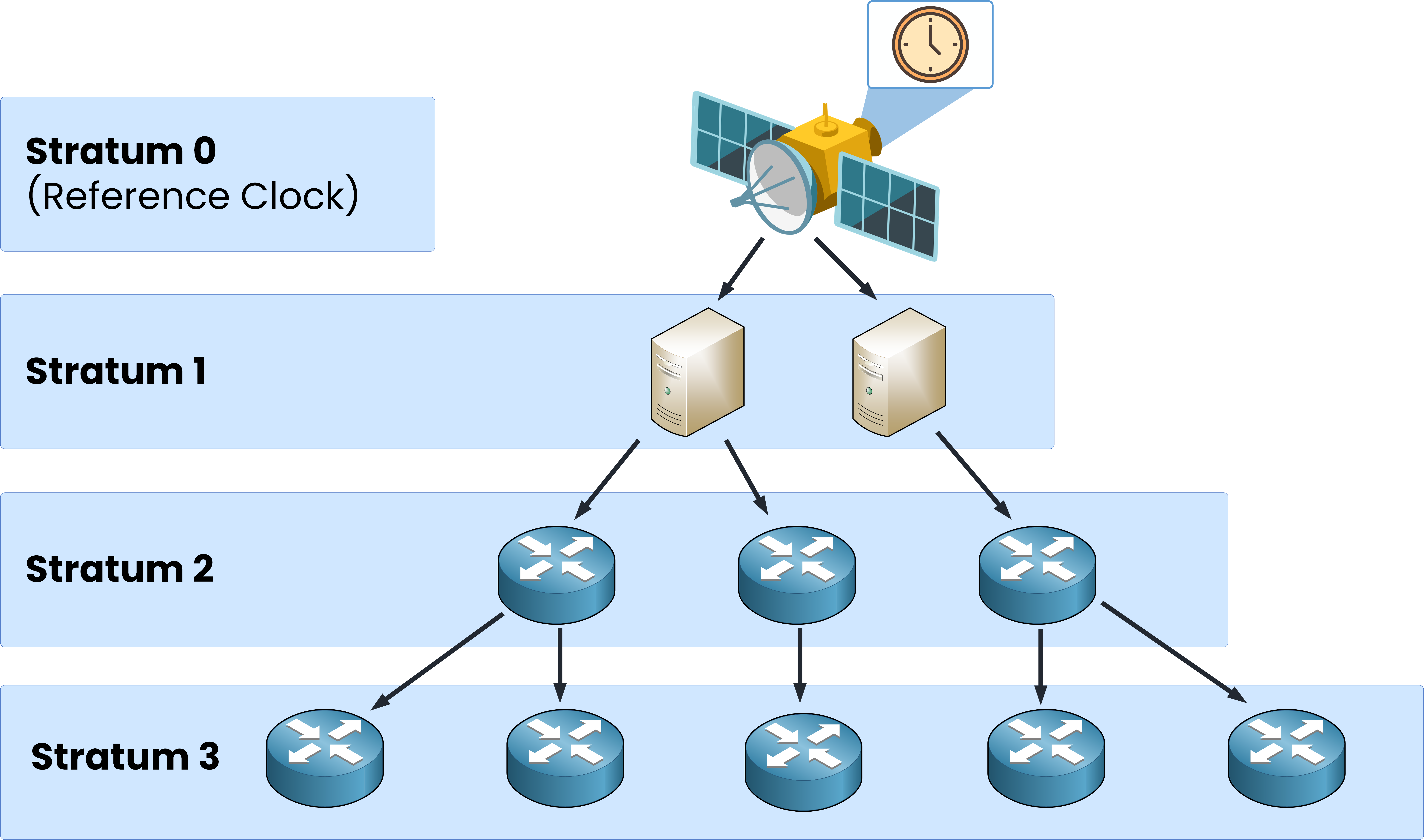
Figure 4 – Network Time Protocol stratum hierarchy
As you go down the layers, the stratum number increases. Usable levels are 1 to 15; Stratum 16 means the device is unsynchronized.
In a typical NTP network, a Stratum 1 Server is directly connected to the reference clock.

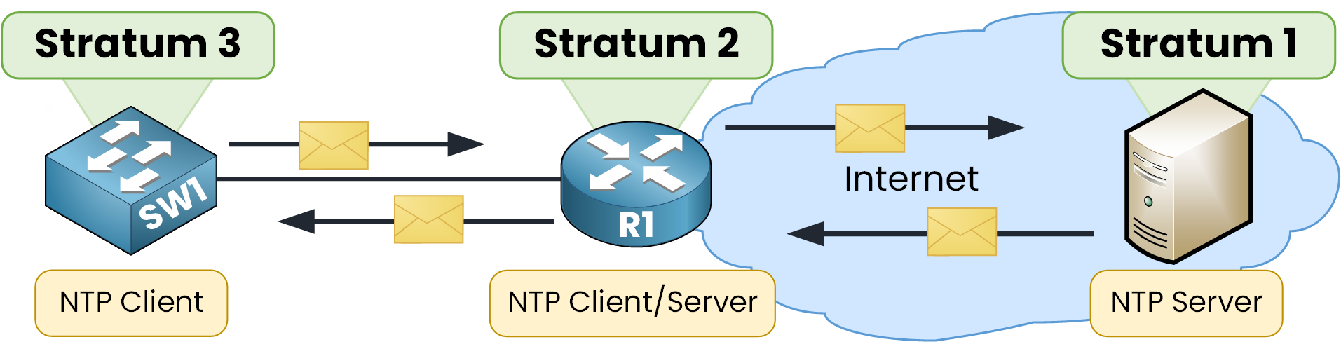
Figure 5 – NTP Client-Server Communication by Stratum
Then a Stratum 2 device synchronizes to Stratum 1 (client role) and can serve time to lower levels. A Stratum 3 device is usually client-only, learning time from Stratum 2.
It’s a hierarchy: as the stratum increases, accuracy decreases slightly due to added delay. Clients therefore prefer the lowest-stratum reachable server.
Answer the question below
Which UDP port does NTP use?
Before using Network Time Protocol, we need to sure you can set and verify the local clock on Cisco Devices. We’ll then point the devices to an NTP Server and interpret the verification outputs.
For the CCNA you don't need to know a lot of commands, so I'll show you the essentials you'll need to know.
Local Time
You can manually set the time zone and local clock on your network device.

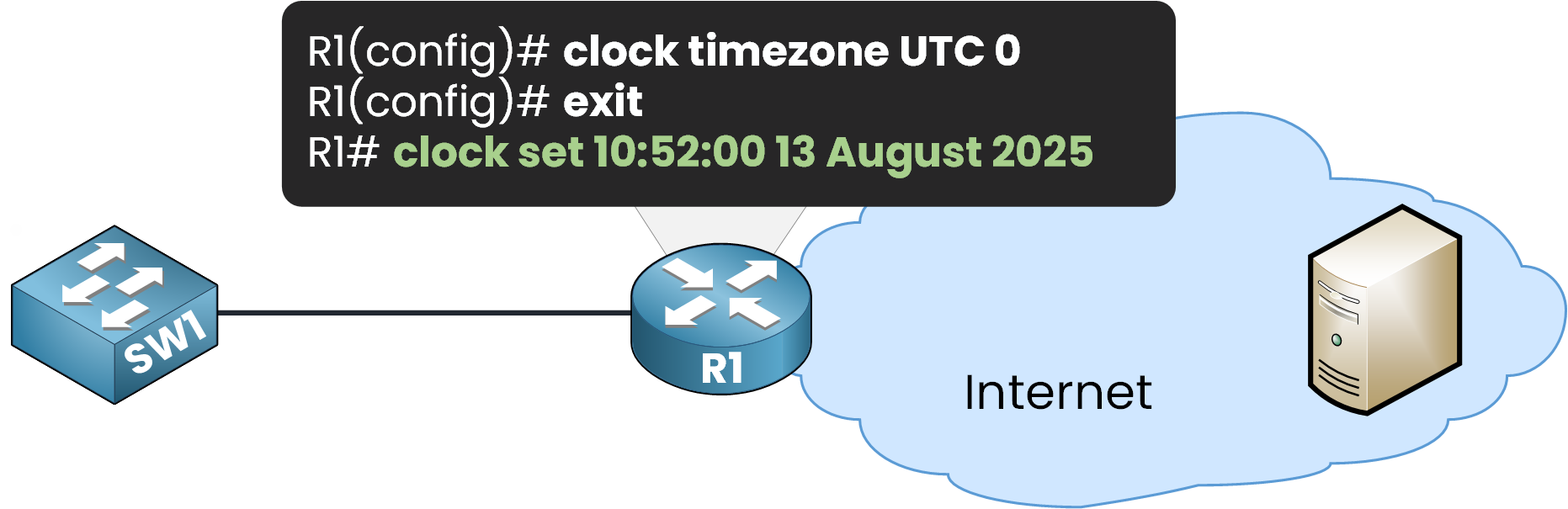
Figure 6 – Setting local time on a Cisco router
To verify that the clock has been updated, use
show clock detailR1# show clock detail 10:52:5.540 UTC Wed Aug 13 2025 Time source is user configurationYou can see the configured time, with a few seconds difference because the command was run shortly after setting it. The line Time source is user configuration confirms the clock was set manually.
In an enterprise network, manually setting the time on each device takes a lot of time. Plus, clocks can still drift apart. This is where NTP becomes essential.
Configure NTP Server
Now that we understand why NTP is useful, let’s configure a device to use an NTP Server for automatic time synchronization.

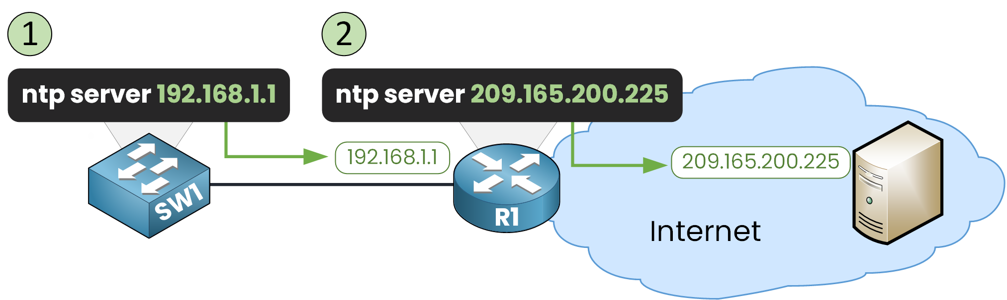
Figure 7 – NTP Server configuration steps
The basic command is
ntp server ip addressStep 1 – Point SW1 to the Internal NTP Server (R1)
In our example, SW1 will get its time from the NTP Server 209.165.200.225.
However, that Server is reachable only through R1’s interface 192.168.1.1, so SW1 will be configured to use R1 as its NTP source:SW1(config)# ntp server 192.168.1.1This tells SW1 to request time from R1.
Step 2 – Check the Initial NTP Status
We can check if synchronization has occurred using
show ntp statusSW1# show ntp status Clock is unsynchronized, stratum 16, no reference clock nominal freq is 250.0000 Hz, actual freq is 249.9990 Hz, precision is 2**24 reference time is 00000000.00000000 (00:00:00.000 UTC Mon Jan 1 1990) clock offset is 0.00 msec, root delay is 0.00 msec root dispersion is 0.00 msec, peer dispersion is 0.00 msec. loopfilter state is 'FSET' (Drift set from file), drift is - 0.000001193 s/s system poll interval is 4, never updated.At this stage, Clock is unsynchronized and stratum 16 (the default value for an unsynchronized device).
This happens because R1 has not yet been configured to use an external NTP Server.Step 3 – Verify NTP Associations
Another useful command is
show ntp associationsSW1# show ntp associations address ref clock st when poll reach delay offset disp ~192.168.1.1 .INIT. 16 - 64 0 0.00 0.00 0.12 * sys.peer, # selected, + candidate, - outlyer, x falseticker, ~ configuredHere:
~ configured means SW1 has been told to use 192.168.1.1 (R1) as an NTP Server.
.INIT. means R1 has not yet sent valid time information.
Step 4 – Configure R1 to Use the Public NTP Server
Let’s configure R1 to get time from the public NTP Server 209.165.200.225:
R1(config)# ntp server 209.165.200.225From this point on, R1 will begin receiving timestamps from the internet-based NTP Server.
Step 5 - Wait For Synchronization
Synchronization can take up to 30 minutes in a real network.
In Packet Tracer, you can speed this up by using the Fast Forward Time option.
Once R1 is synchronized, SW1 will also be able to synchronize through R1.

Figure 8 – NTP Server sends timestamp to NTP clients.
Step 6 – Verify R1 Synchronization
On R1, check the NTP status:
R1# show ntp status Clock is synchronized, stratum 2, reference is 209.165.200.225 nominal freq is 250.0000 Hz, actual freq is 249.9990 Hz, precision is 2**24 reference time is EC1D64C1.00000225 (22:48:33.549 UTC Thu Aug 14 2025) clock offset is 0.00 msec, root delay is 0.00 msec root dispersion is 767.34 msec, peer dispersion is 0.48 msec. loopfilter state is 'CTRL' (Normal Controlled Loop), drift is - 0.000001193 s/s system poll interval is 6, last update was 18 sec ago.Here you can see:
Clock is synchronized → R1 has locked onto the external time source.
Stratum 2 → R1 is two steps away from the reference clock.
Reference is 209.165.200.225 → This matches the Server we configured earlier.
Step 7 – Verify SW1 Synchronization
Once R1 is synchronized, SW1 will get its time from R1. Let’s check:
SW1# show ntp status Clock is synchronized, stratum 3, reference is 192.168.1.1 nominal freq is 250.0000 Hz, actual freq is 249.9990 Hz, precision is 2**24 reference time is EC1D642A.0000019F (22:46:2.415 UTC Thu Aug 14 2025) clock offset is 0.00 msec, root delay is 0.00 msec root dispersion is 775.07 msec, peer dispersion is 0.48 msec. loopfilter state is 'CTRL' (Normal Controlled Loop), drift is - 0.000001193 s/s system poll interval is 6, last update was 36 sec ago.Key points:
Reference is 192.168.1.1 → SW1 is using R1 as its NTP Server.
Stratum 3 → SW1 is one level below R1 (stratum 2).
Step 8 – Check NTP Associations on SW1
SW1# show ntp associations address ref clock st when poll reach delay offset disp *~192.168.1.1 209.165.200.225 2 49 64 377 0.00 0.00 0.48 * sys.peer, # selected, + candidate, - outlyer, x falseticker, ~ configuredThis tells us:
SW1 is synchronized with 192.168.1.1 (R1).
R1’s own reference clock is 209.165.200.225 (the public NTP Server).
R1 is stratum 2, so SW1 is stratum 3.
Step 9 - Confirm the Time Source
Finally, check the clock details on SW1:
SW1# show clock detail 22:51:7.176 UTC Thu Aug 14 2025 Time source is NTPThis confirms SW1 is now successfully synchronized via NTP.
Answer the question below
What command checks if a Cisco device is synchronized with NTP?
An important concept to understand is the NTP Master feature.
This allows a device to act as an NTP Server using its own internal clock if the primary NTP Server becomes unavailable.
Figure 9 – NTP Master and Server configuration
On a Cisco device, you can enable this mode using
ntp mastercommand.In our example, R1 is configured both as an NTP client (while the internet-based NTP Server is available) and as an NTP Server for the internal network.
When the Primary NTP Server Fails
If the internet NTP Server is unreachable, R1 still gives time to the internal network. It now uses its local hardware clock as the reference.

Figure 10 – NTP Server failover scenario
This ensures that:
Internal devices remain synchronized with each other.
The network avoids large time drifts during the outage.
This fallback mode won’t be as accurate as using an external reference. But, it serves as a reliable backup until the main NTP source is back online.
Answer the question below
What command makes a Cisco device act as an NTP server using its own clock?
Up to this point, we’ve worked with simple examples.
In a big enterprise network, you often set up several NTP servers. This ensures redundancy and reliability.Many NTP Servers for Redundancy

Figure 11 – NTP Clients and Servers with many peers
In this example, the public NTP Servers from Amazon (1.amazon.pool.ntp.org and 2.amazon.pool.ntp.org) are used to synchronize the internal network.
Configuring NTP Master
The border routers (R1 and R2) are configured as NTP Masters with a stratum level of 6, using the command:
ntp master 6By default,
ntp masteruses stratum 8. Here, we lower it to 6 so NTP clients see the routers as more reliable sources during an outage.
Figure 12 – NTP configuration with Loopback Source and many Servers
This means that if external servers can't be reached, these routers will still provide time to internal devices using their own clock.
Using a Loopback Interface as the NTP Source
It’s also common to configure a loopback interface as the NTP source on the Server. This way, the NTP packets are sent using the loopback IP address, which remains the same even if a physical interface changes state. You can do this with
ntp source loopback0Using a loopback source improves stability and avoids IP changes that could disrupt the time synchronization.
Answer the question below
What interface is often used as the NTP source for stability?
The following points summarize the most important concepts and best practices covered in this lesson.
Core concepts
NTPv4 over UDP/123 (RFC 5905). Devices exchange timestamps, not human-readable dates.
Stratum: 0 = reference (GPS/atomic), 1 = servers tied to 0, 2+ = downstream.
Lower is better; 16 = unsynchronized.Device clocks drift. Prefer NTP over manual time for accuracy.
Minimal setup and checks
Configure on clients:
ntp server.Verify with three commands:
show ntp status(sync state, stratum, reference)show ntp associations(*= selected; check st)show clock detail(time source should be NTP)Tip: set
clock timezone …. If time is wildly wrong, do oneclock set …, then let NTP maintain it.
Operations and troubleshooting
Be patient: NTP converges slowly (polls in minutes).
NTP Master :
ntp master [stratum](default 8) keeps clocks coherent if upstream NTP fails.Enterprise NTP Networks: redundant NTP source, loopbacks with
ntp source loopback0
Answer the question below
Network Time Protocol (NTP)
Network Time Protocol (NTP) keeps routers, switches, and servers synchronized with a precise time source. In this lesson, you’ll learn how NTP works, why it matters for security and troubleshooting, and how to configure it on Cisco devices.