1. Introduction
As you know, a VLAN creates a separate Subnet and Broadcast Domain. Devices inside the same VLAN can communicate directly at Layer 2, but as soon as a host in a VLAN needs to talk to a host in another VLAN, a problem appears: VLANs cannot communicate with each other without a Layer 3 device.
That’s where InterVLAN Routing comes in. It allows traffic to move between VLANs using either a router or a multilayer switch.
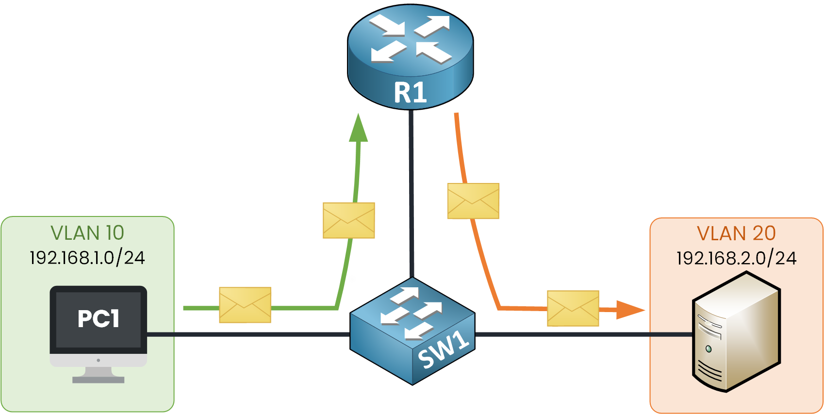
Figure 1 – InterVLAN Routing Process
In this lesson, we’ll explore the three main methods of InterVLAN Routing:
Legacy InterVLAN Routing – the old way, limited and no longer used today.
Router-on-a-Stick – a simple solution for small to medium networks.
Layer 3 Switch with SVIs – the modern, scalable solution for enterprises.
2. Legacy InterVLAN Routing
The first method to look at is Legacy InterVLAN Routing.
This solution uses a router with multiple physical Ethernet interfaces. Each router interface connects to a switch port assigned to a different VLAN. This interfaces acts as that VLAN’s default gateway (R1 G0/1 for VLAN 10, R1 G0/3 for VLAN 20).
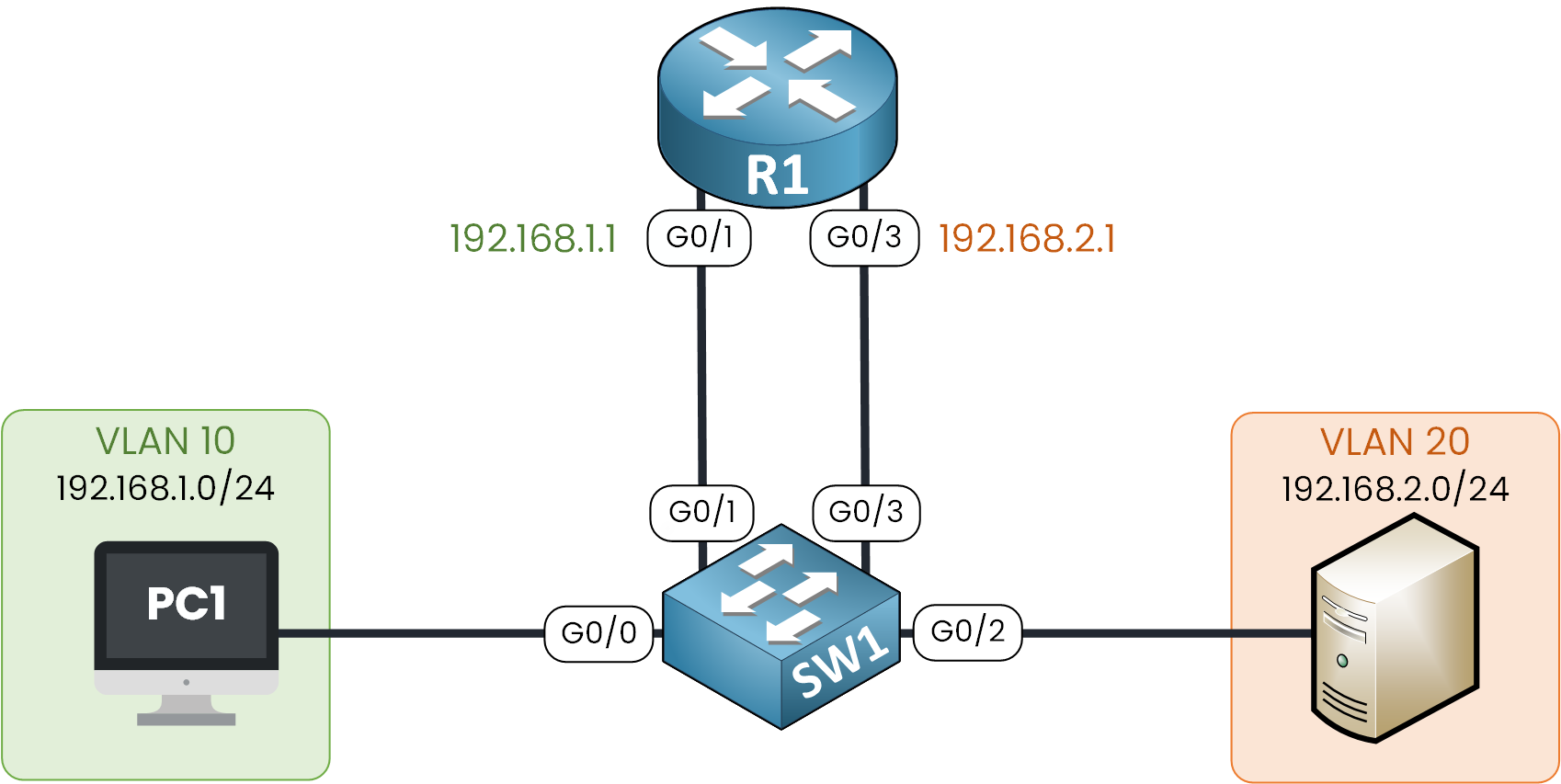
Figure 2 – Legacy InterVLAN Routing Topology
In our example, we have two VLANs:
VLAN 10 (192.168.1.0/24) with PC1
VLAN 20 (192.168.2.0/24) with the Server
On switch SW1 :
Interfaces G0/0 and G0/1 are associated with VLAN 10
While Interfaces G0/2 and G0/3 are associated with VLAN 20
When PC1 sends a packet to the server in VLAN 20, since the destination is on another subnet, PC1 forwards the packet to its default gateway 192.168.1.1.
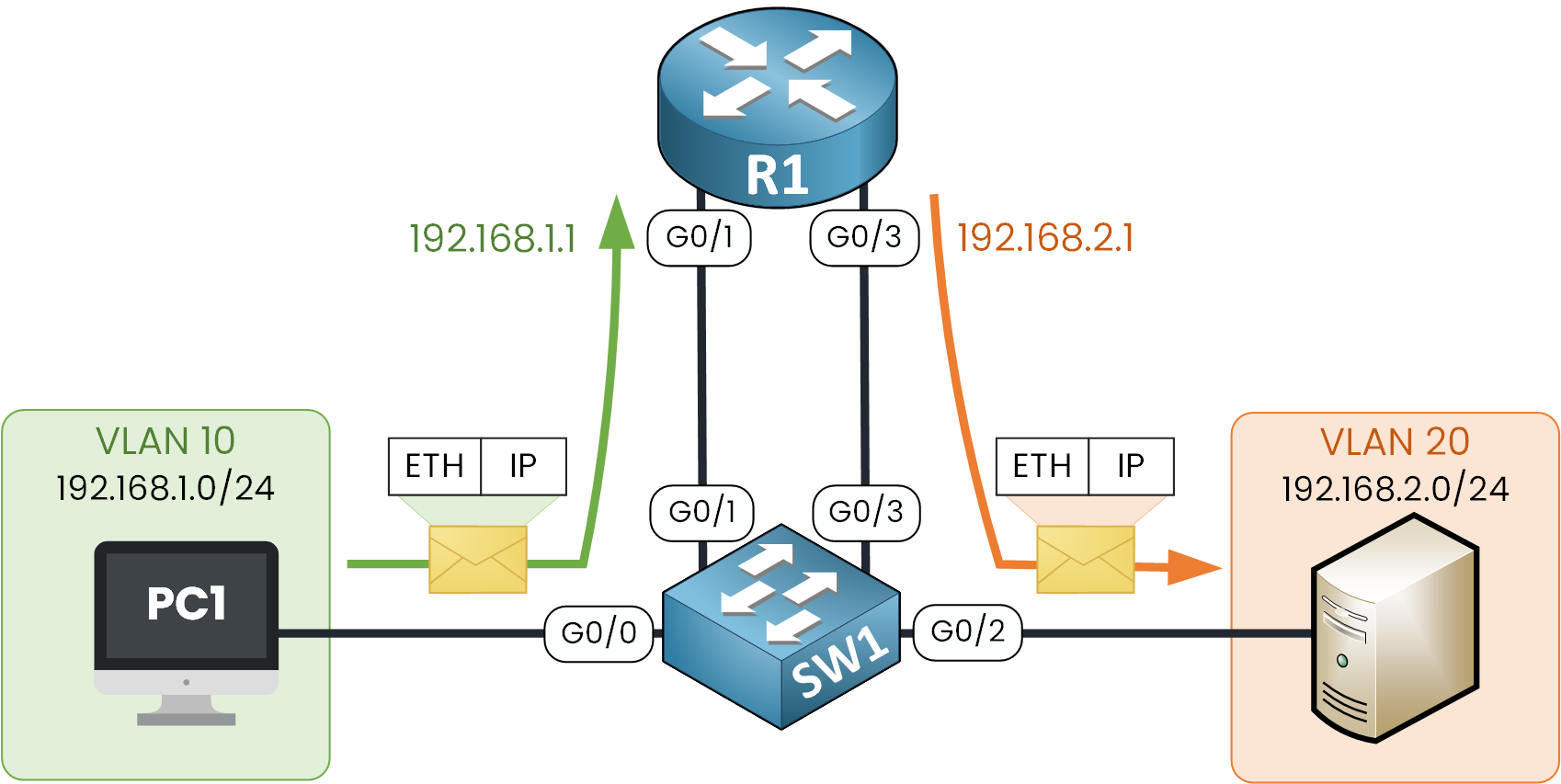
Figure 3 – Legacy Router-on-a-Stick Packet Flow
R1 receives the packet on interface G0/1, examines the destination IP, and routes the packet out interface G0/3 to reach the server in VLAN 20. SW1 then forwards the frame to the server.
Limitations
Since legacy interVLAN routing uses one physical interface per VLAN, this solution is not scalable because routers have a limited number of physical interfaces. Using one physical router interface per VLAN could quickly exhaust the router’s capacity.
In our example, R1 used two separate Ethernet interfaces to route the traffic between VLAN 10 and VLAN 20.
Now imagine we need to add 10 VLANs: it would require 10 more physical interfaces between R1 and SW1, which is obviously not scalable.
This method of interVLAN routing is no longer implemented in production networks nowadays but keep in mind this was the first method ever created.
3. Router on a Stick
Router on a Stick method overcomes the limitation of Legacy interVLAN Routing. in this method the router only needs one physical Ethernet interface to route traffic between multiple VLANs.
As you can see below, interface G0/1 of R1 is configured as an 802.1Q trunk and connected to port G0/1 also configured as the trunk on SW1. This trunk link between the two devices allows traffic from multiple tagged VLANs.
Figure 4 – Router-on-a-Stick Topology
In order to have multiple Layer 3 default gateways for each VLAN on a single physical link of R1, the router interface G0/1 is configured with subinterfaces. These subinterfaces are software-based virtual interfaces.
We need to create two subinterfaces, one for VLAN 10 and one for VLAN 20.
Figure 5 – InterVLAN Routing with Sub-Interfaces
When PC1 in VLAN 10 wants to send traffic to the server in VLAN 20, the packet first enters switch SW1 on port G0/0. The switch forwards the frame across the trunk to R1, tagging it with VLAN 10.
The router receives the frame on the physical interface G0/1, reads the VLAN tag, and forwards the packet to the sub-interface G0/1.10.
Figure 6 – Router-on-a-Stick Packet Flow
The router then makes a routing decision. Since the destination IP belongs to VLAN 20, the packet is forwarded out of subinterface G0/1.20, which corresponds to this VLAN.
Before leaving the router, the frame is tagged with VLAN 20 and sent on the physical interface G0/1 towards SW1. The switch then delivers the frame to the server in VLAN 20 by using interface G0/2
Limitations
The Router-on-a-Stick design is cost-effective, since it only requires one physical interface. However, as you may have notice, all inter-VLAN traffic must enter and exit through the same link, creating a serious bottleneck.
To avoid this limitation, the last created and recommended approach to use is SVIs (Switched Virtual Interfaces) on a Layer 3 switch.
4. Layer 3 Switch with SVIs
The modern method of performing interVLAN routing is to use a Layer 3 switch with Switched Virtual Interfaces (SVIs).
An SVI is a virtual Layer 3 interface configured for a VLAN on the switch. Each SVI acts like a router interface, providing Layer 3 processing for packets.
Figure 7 – InterVLAN Routing using Switch Virtual Interfaces (SVIs)
In this example, the switch has two SVIs:
VLAN 10 SVI with IP address 192.168.1.1
VLAN 20 SVI with IP address 192.168.2.1
These SVIs act as the default gateways for hosts in their respective VLANs.
How the packet flow works
When PC1 in VLAN 10 wants to communicate with the server in VLAN 20, it sends its packet to the default gateway (192.168.1.1). The packet enters the switch on port G0/0, which belongs to VLAN 10, and is processed by the VLAN 10 SVI.
Figure 8 – InterVLAN Routing with SVI Packet Flow
The switch performs a Layer 3 routing decision internally. Since the destination is in VLAN 20, the packet is routed to the VLAN 20 SVI. The switch then forwards the packet out of port G0/2 toward the server.
Advantages of SVIs on a Layer 3 Switch
Using SVIs on a Layer 3 switch is the most efficient way to perform inter-VLAN routing.
Switching and routing are processed directly in hardware, which makes it much faster than Router-on-a-Stick.
By configuring SVIs and using EtherChannel, the available bandwidth can scale up, removing the limitation of a single physical link.
For these reasons, SVIs have become the standard design in modern campus LANs.
Limitation
The only drawback is the higher cost of Layer 3 switches compared to Router-on-a-Stick, but their speed and scalability make them the preferred choice in enterprise networks.
5. Conclusion
InterVLAN Routing is essential to allow communication between VLANs. Over time, three main methods have been used:
Legacy Inter-VLAN Routing – each VLAN required a dedicated physical router interface. Simple but not scalable, now obsolete.
Router-on-a-Stick – a cost-effective solution using a single router interface with subinterfaces, but limited by the bottleneck of one physical link.
Layer 3 Switch with SVIs – the modern solution. Routing is done in hardware, supports EtherChannel for scalability, and is the standard in campus LANs.
Key takeaway
Legacy routing is outdated, Router-on-a-Stick is fine for small networks, but SVIs on a Layer 3 switch are the most efficient and scalable method for inter-VLAN routing.
In the next lessons, we will see how to configure Router-on-a-Stick and SVI inter-VLAN routing step by step.