Today, the Spine and Leaf Architecture Cisco developed is the foundation of most modern data center designs.
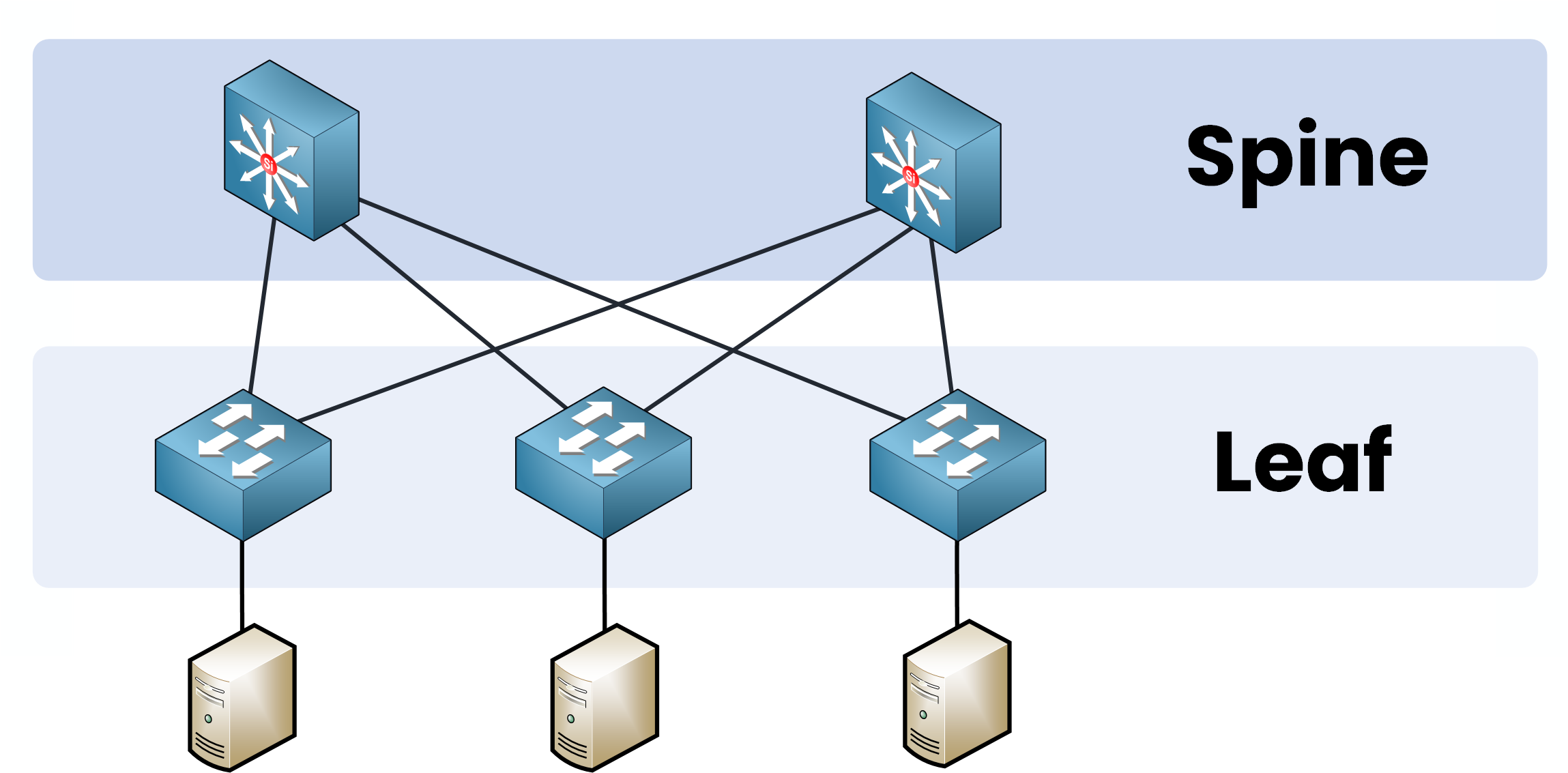
Figure 1 – Spine and Leaf Architecture
But how did it become so popular?
To really understand this, let’s take a step back together and revisit the traditional Three-Tier Architecture, the design that shaped network infrastructures for years when traffic patterns were very different from today.
Answer the question below
Back in the early 2000s, networks were built for a different world.
At that time:
Data centers had fewer servers.
Applications were simple, mostly client-server based.
Latency wasn’t a critical issue.
Bandwidth requirements were modest.
The traditional Three-Tier Architecture was perfect for these needs.
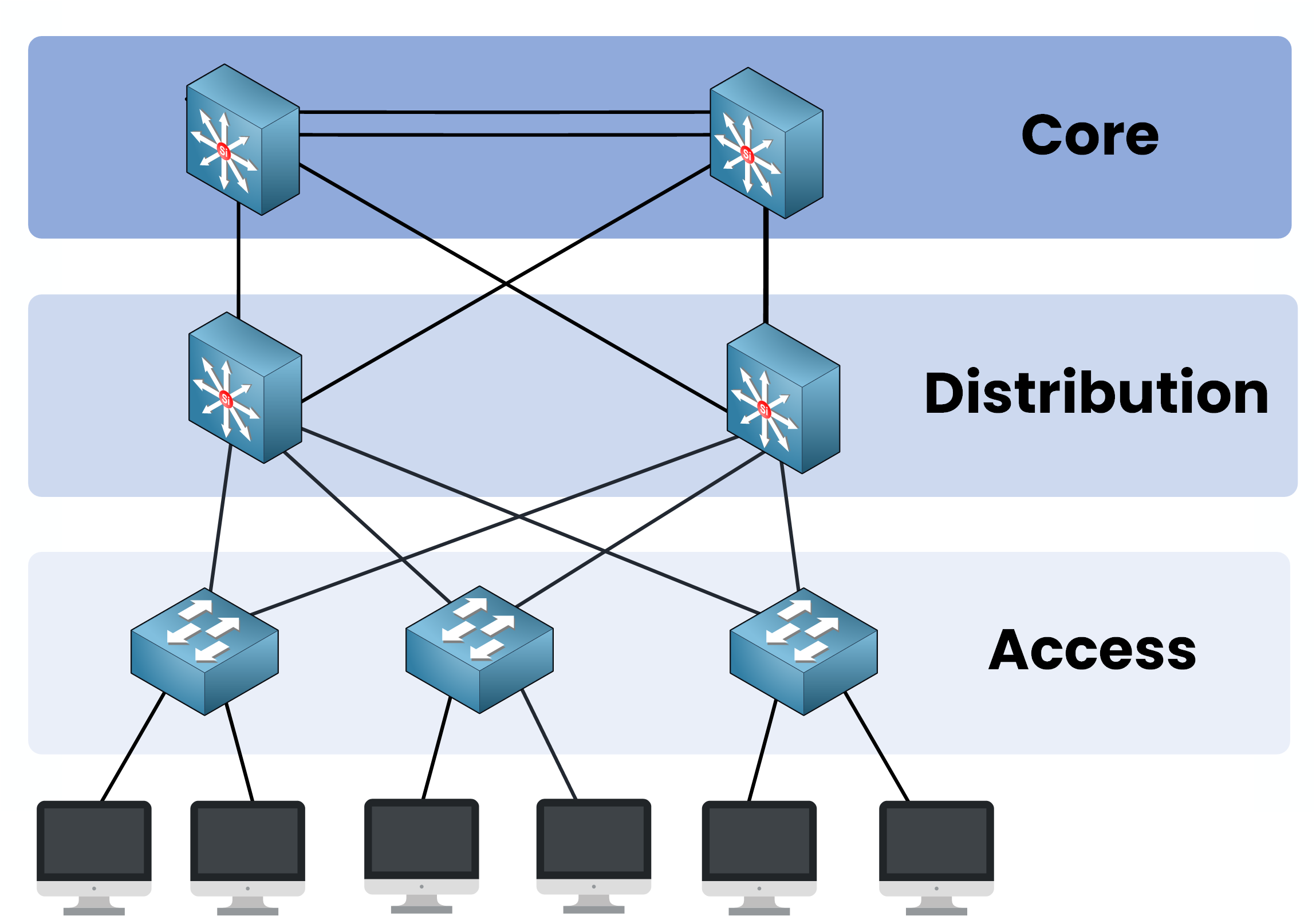
Figure 2 – Traditional Three-Tier Architecture
In this design:
Access to Distribution = Layer 2 switching
Distribution to Core = Layer 3 routing
To prevent loops at Layer 2, the network depends on the Spanning Tree Protocol (STP).
North-South Traffic
Originally, networks were optimized for North-South traffic, traffic flowing between clients and servers, typically moving in and out of the data center.
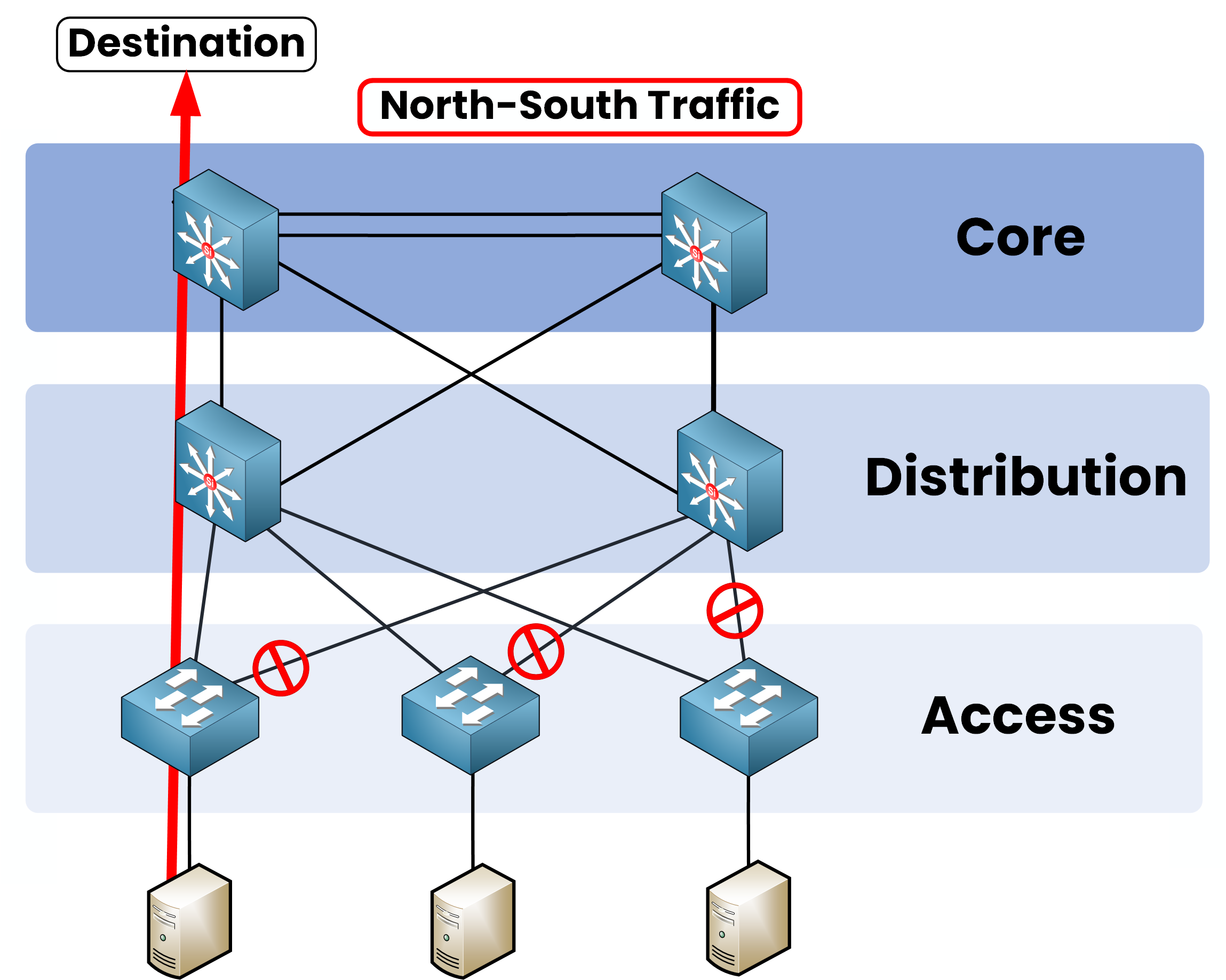
Figure 3 – North–South Traffic Flow
In that scenario:
Latency wasn’t critical.
Some blocked links by STP were acceptable.
Bandwidth demand was low.
East-West Traffic
However, as data center traffic patterns evolved, a new type of traffic emerged:
East-West traffic, server-to-server communication inside the data center became dominant.
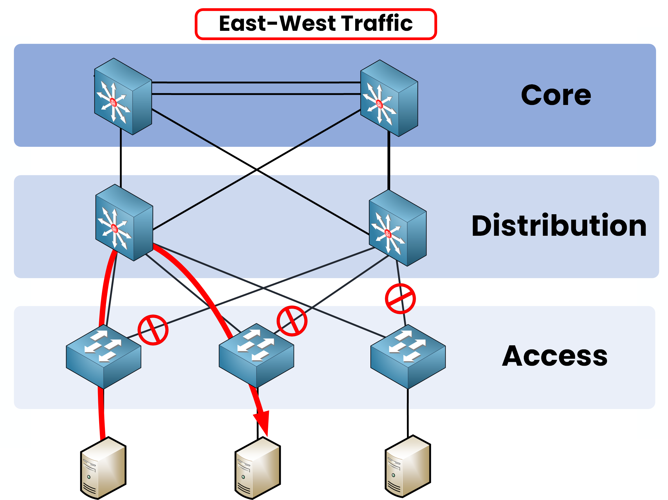
Figure 4 – East–West Traffic Limitation
In this new environment:
STP blocks redundant links, preventing full bandwidth usage.
Bandwidth is wasted, and servers can’t leverage all available paths.
Multiple hops across the Access, Distribution, and Core layers increased latency.
Initially, the three-tier design worked fine but a major bottleneck occurred as East-West traffic exploded!
Answer the question below
To solve this, Cisco introduced vPC (Virtual Port-Channel) and it was a real step forward.
With vPC:Two active uplinks from each Access switch to the Distribution layer.
Better bandwidth utilization.
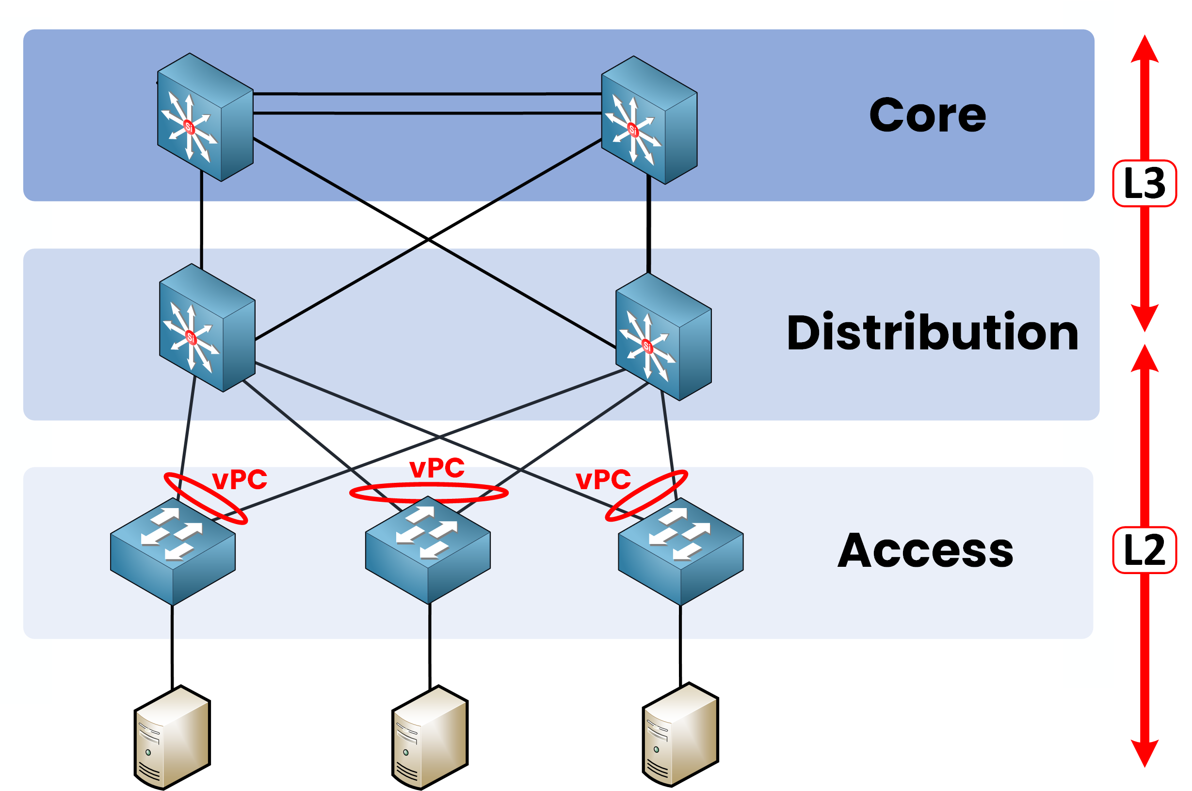
Figure 5 – Enhanced Layer 2 with vPC
40 % Complete: you’re making great progress
Unlock Premium to get the rest of this lesson
If you want to keep going with your CCNA journey, unlock your all-in-one platform to get ready for the CCNA exam.
Access all CCNA lessons
Practice with hands-on labs
Train with Practice exams and Quizzes
Progress tracking in your dashboard
Made by network engineers - CCNP certified
Unlock Premium1151 learners continued their CCNA journey this month
Spine and Leaf Architecture Cisco
Spine and Leaf Architecture is the network design used in modern data centers to achieve high performance and scalability. In this lesson, you’ll learn its key principles and why it has replaced older models.