Multiple Spanning Tree (MST), defined in IEEE 802.1s and now part of 802.1Q, is a Layer 2 protocol that lets you group multiple VLANs into a single spanning tree instance.
Before seeing how it works, you need to feel the problem it solves on a real enterprise network.The Network You Inherited
You are the network engineer of a mid-sized company.
Three distribution switches, SW1, SW2, SW3 carry every VLAN of the business.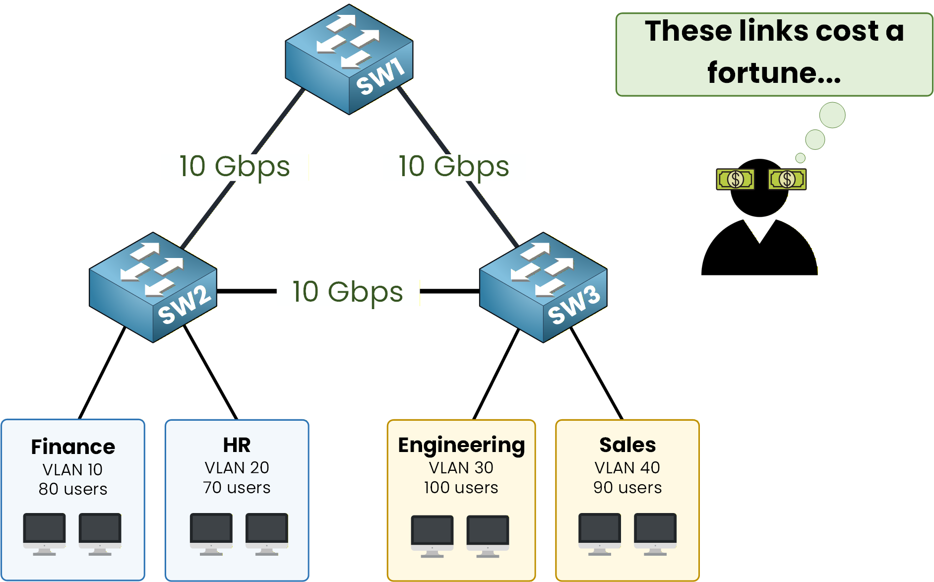
Figure 1 – Triangle links, four VLANs
Behind them sit four departments: Finance and HR on VLAN 10 and 20, Engineering and Sales on VLAN 30 and 40.
The three switches are wired in a full triangle with three 10 Gbps uplinks. The company paid for that redundancy, so all three links should carry traffic, yet you'll see in a moment that classic spanning tree wastes one of them.
Answer the question below
Read the topology and continue.
Per-VLAN Architecture in Rapid-PVST+
By default, Cisco switches utilize a Per-VLAN implementation of Spanning Tree (PVST+ or Rapid-PVST+), where a dedicated STP instance is maintained for every configured VLAN. For instance, a network with four active VLANs will result in four distinct, independent spanning tree topologies.
Each tree elects a root bridge using the same criteria: lowest Bridge ID wins.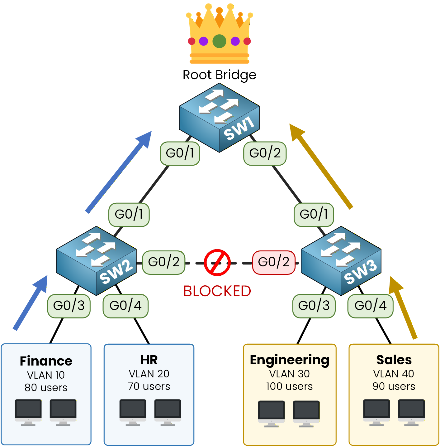
Figure 2 – All VLANs toward SW1
Since all your switches have the default priority of 32768, the switch with the lowest MAC address is elected, let's say SW1.
The four trees all pick the same root. And if four trees have the same root, they all block the same redundant link to prevent loops.The link between SW2 and SW3 is now blocked for every VLAN.
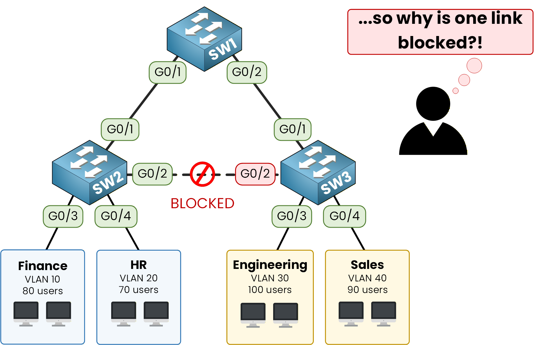
Figure 3 – SW2-SW3 link blocked (PVST+)
One of your three 10 Gbps uplinks carries zero packets.
The company paid for redundancy and capacity, and Rapid-PVST+ only gives you redundancy.Answer the question below
In Rapid-PVST+, how many spanning tree instances run when you have 4 VLANs?
MST groups several VLANs into a single spanning tree, so you end up with fewer instances to manage.
The real benefit comes from choosing a different root bridge per instance, which is what unlocks load-balancing across your uplinks.User Traffic on Different Paths
You build two instances for your lab:
MST instance 1 (MSTI 1) carries VLAN 10 and 20, with SW1 as root.
MST instance 2 (MSTI 2) carries VLAN 30 and 40, with SW2 as root.
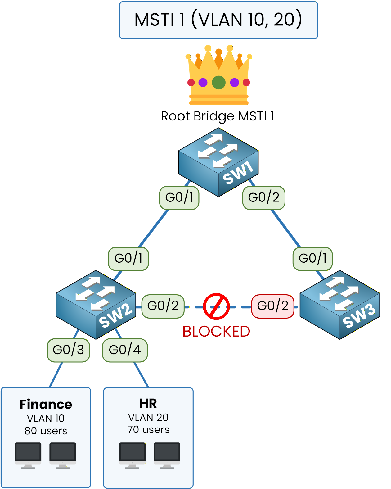
Figure 4 – MSTI 1: VLANs 10-20
Start with MSTI 1. VLAN 10 (Finance) and VLAN 20 (HR) are mapped to this instance, and SW1 is the root bridge.
Every Finance or HR frame climbs toward SW1.When a Finance user sends a packet, it rides the blue path from SW2, up to SW1 via G0/1.
The G0/2 trunk between SW2 and SW3 stays blocked for MSTI 1 only.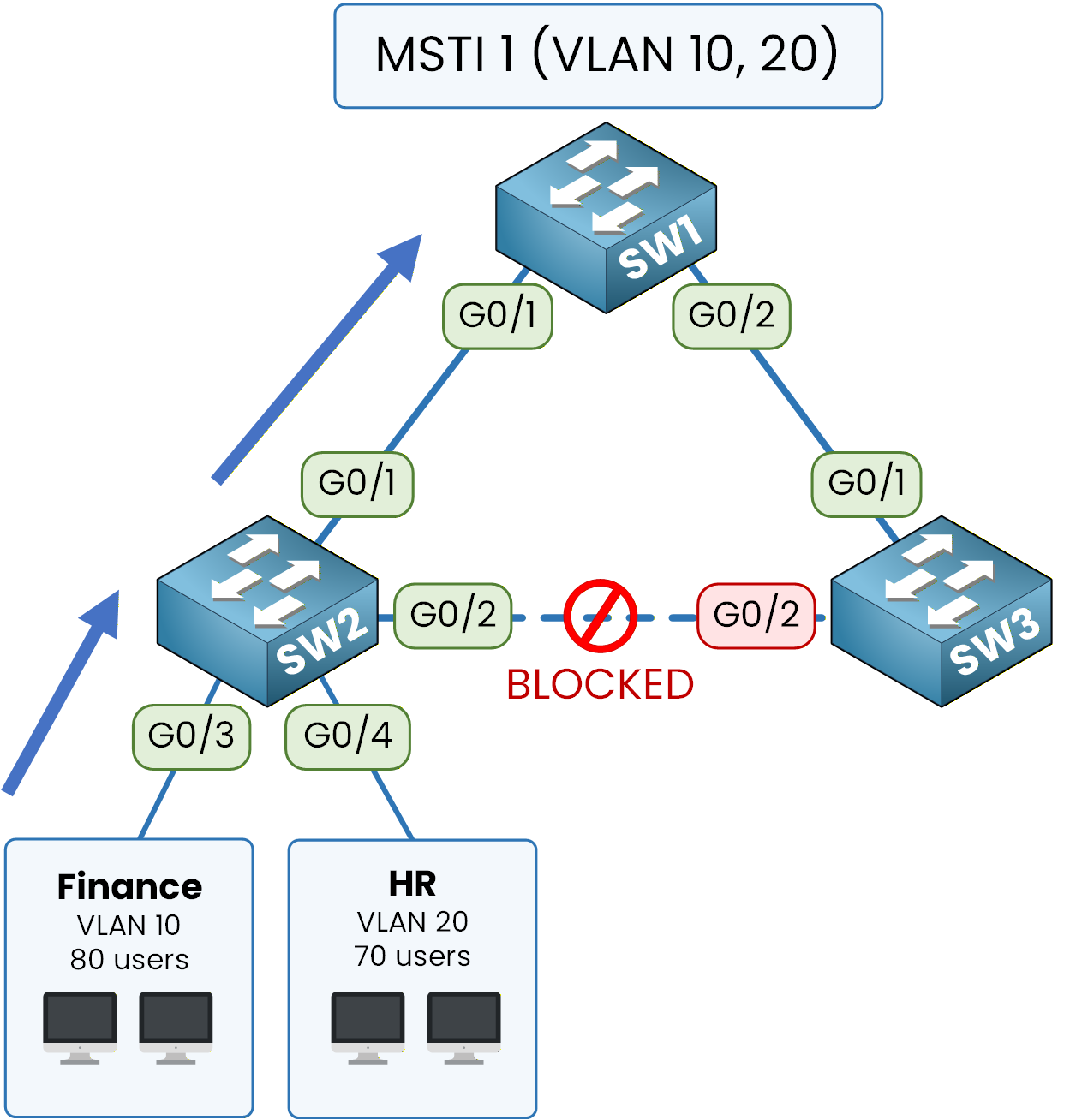
Figure 5 – MSTI 1: Forwarding toward SW1
Now look at MSTI 2. VLAN 30 (Engineering) and VLAN 40 (Sales) are mapped to this instance, but this time SW2 is the root, not SW1.
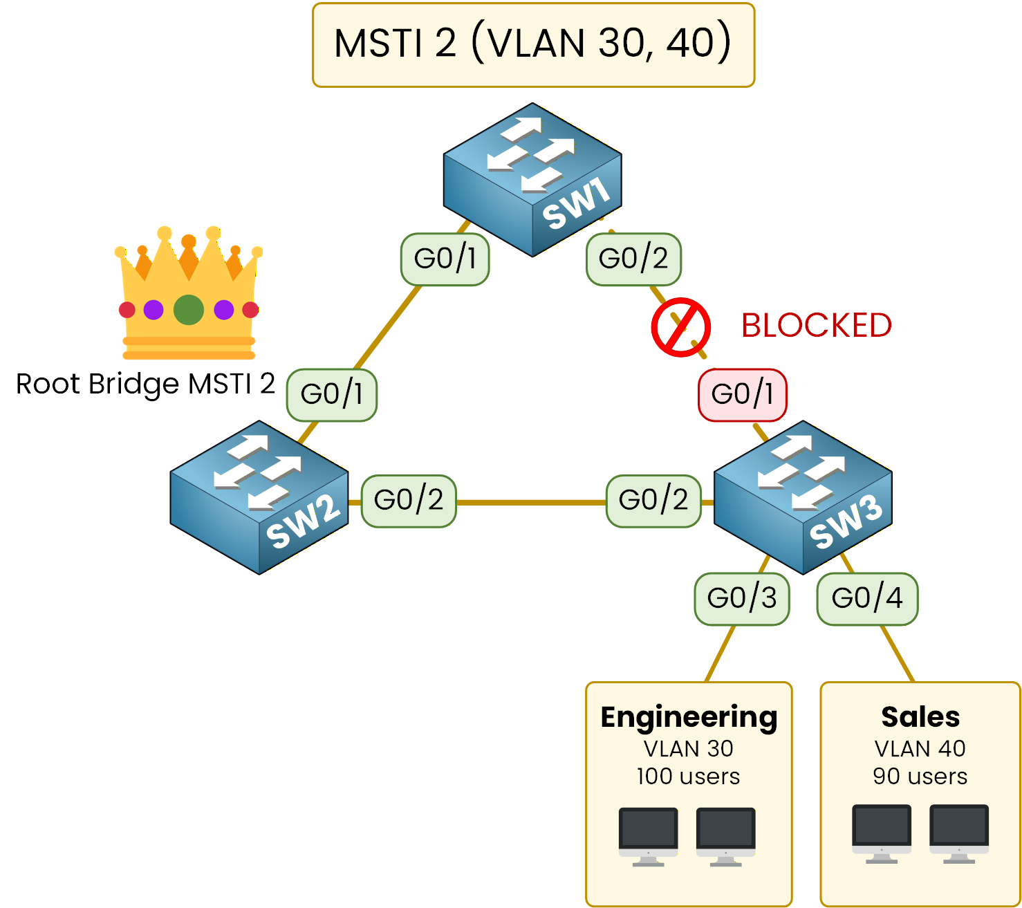
Figure 6 – MSTI 2: VLANs 30-40
An Engineering user sending a packet rides the amber path from SW3, toward SW2.
This time the trunk between SW1 and SW3 is the one that gets blocked, for MSTI 2 only.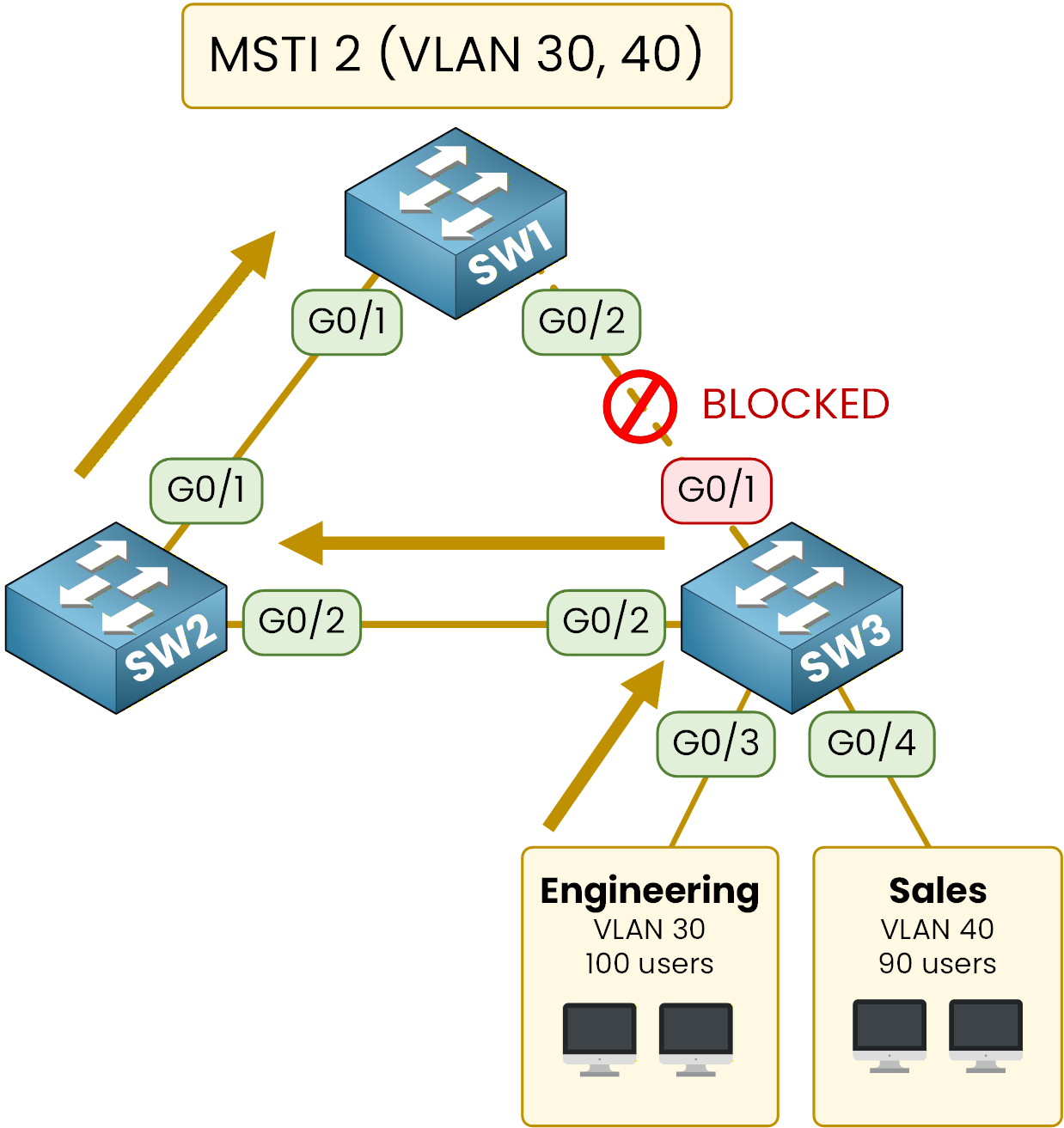
Figure 7 – MSTI 2: Forwarding toward SW2
Same cables, same switches, but two different paths.
Every physical uplink now forwards traffic for at least one instance.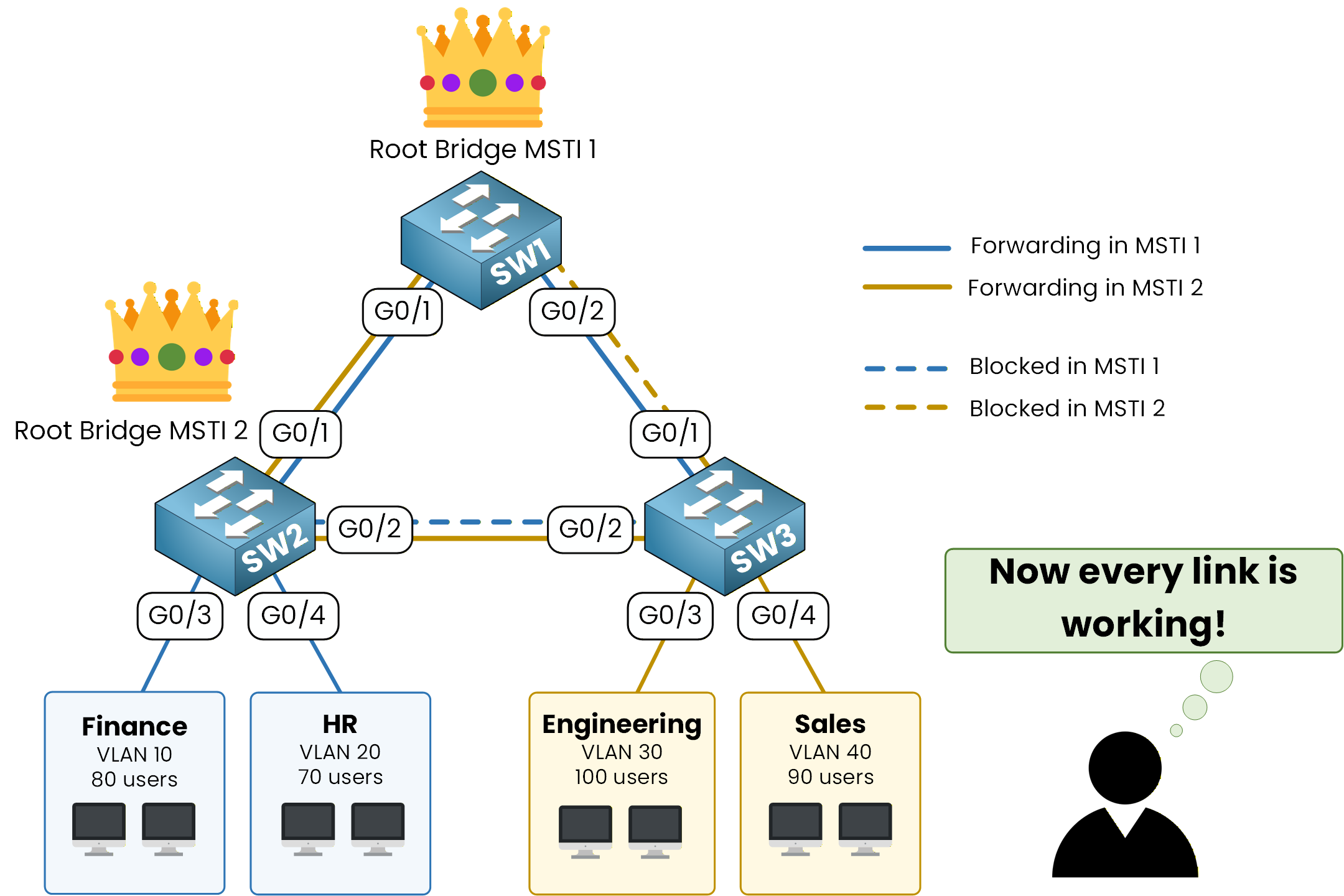
Figure 8 – Balanced paths, zero waste
The link blocked in MSTI 1 is the link forwarding in MSTI 2, and vice-versa.
The IST — Instance 0
Before jumping into configuration, one concept you need to know: instance 0 always exists, even if you don't configure it.
It's called the Internal Spanning Tree (IST) and it catches every VLAN you did not explicitly map to a custom instance.In your lab, that means VLAN 1 and every other unused VLAN stays in MSTI 0 by default.
You still get to pick its root bridge separately.Answer the question below
In this design, which switch is the root for MST instance 2?
You now know what you want to achieve: two MST instances, two different root bridges, every uplink carrying user traffic. Time to make it real on the three switches.
Here is the structure we will follow:
Step 1 – Verify the Layer 2 baseline (VLANs and trunks already exist)
Step 2 – Enable MST mode on SW1, SW2, and SW3
Step 3 – Configure the MST region (name, revision, instance mapping)
Step 4 – Elect the root bridges and verify the topology
Step 5 – Verify the two user paths per interfaceEach step builds on the previous one.
By the end, your network will run two independent MST instances, each with its own root bridge, instead of four separate Rapid-PVST+ trees.Answer the question below
Ready?
The four VLANs and the inter-switch trunks are already configured on SW1, SW2, and SW3.
Before diving into MST, take a minute to confirm the Layer 2 baseline so you know what MST will run on top of.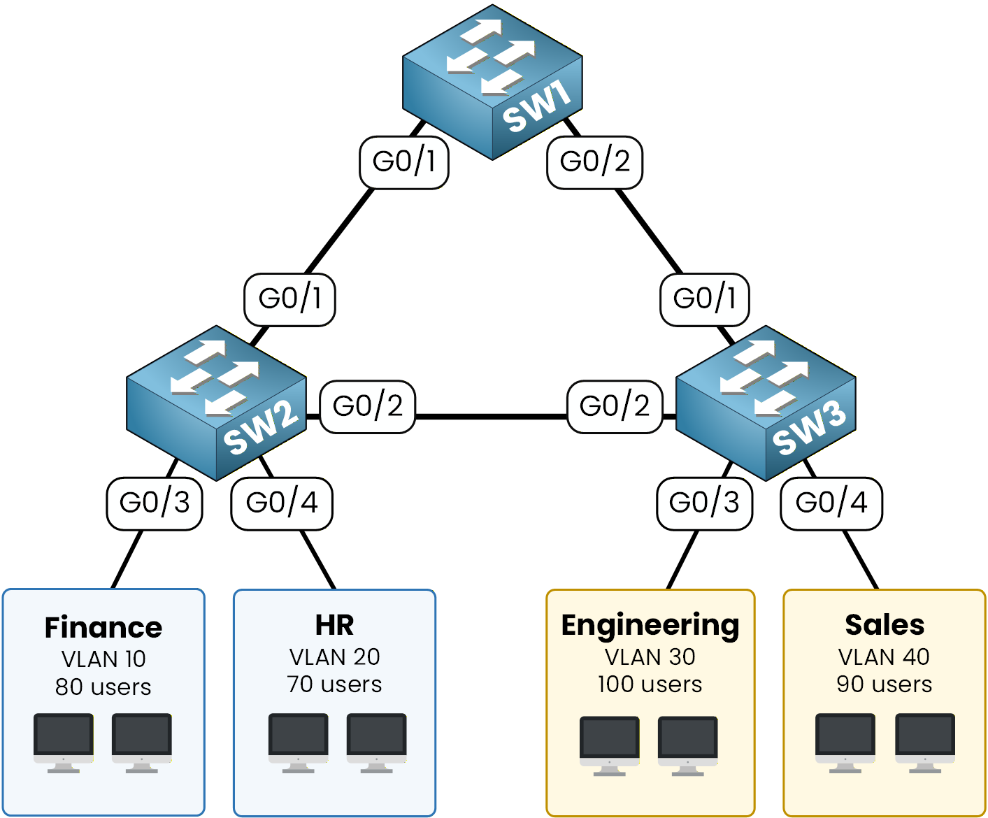
Figure 9 - MST lab network diagram
If you need a refresher on how to create VLANs and configure 802.1Q trunks, see the CCNA Spanning Tree lab.
Check the VLAN Database on Every Switch
Run
show vlan briefon each switch to see the VLAN-to-port mapping. Start with SW1:SW1# show vlan brief VLAN Name Status Ports ---- -------------------------------- --------- ------------------------------- 1 default active Gi0/4, Gi0/5, Gi0/6, Gi0/7 10 FINANCE active 20 HR active 30 ENGINEERING active 40 SALES activeSW1 has all four VLANs but no access ports.
That is expected, it is purely a transit switch with two trunks toward SW2 and SW3.Now SW2:
SW2# show vlan brief
VLAN Name                             Status    Ports
---- -------------------------------- --------- -------------------------------
1    default                          active    Gi0/5, Gi0/6, Gi0/7
10   FINANCE                          active    Gi0/3
20   HR                               active    Gi0/4
30   ENGINEERING                      active
40   SALES                            active
On SW2, Gi0/3 carries Finance (VLAN 10) and Gi0/4 carries HR (VLAN 20).
Together they represent 150 users that will eventually be served by MST instance 1.Finally SW3:
SW3# show vlan brief
VLAN Name                             Status    Ports
---- -------------------------------- --------- -------------------------------
1    default                          active    Gi0/5, Gi0/6, Gi0/7
10   FINANCE                          active
20   HR                               active
30   ENGINEERING                      active    Gi0/3
40   SALES                            active    Gi0/4
SW3 mirrors SW2 but for the other two departments: Gi0/3 carries Engineering (VLAN 30) and Gi0/4 carries Sales (VLAN 40).
These 190 users will be served by MST instance 2.Check the Trunks Between Switches
Use
show interfaces trunkon SW1 to confirm both inter-switch links are active and carry every VLAN.
The output is identical on SW2 and SW3 because the topology is symmetrical.SW1# show interfaces trunk Port Mode Encapsulation Status Native vlan Gi0/1 on 802.1q trunking 1 Gi0/2 on 802.1q trunking 1 Port Vlans allowed on trunk Gi0/1 1-4094 Gi0/2 1-4094 Port Vlans allowed and active in management domain Gi0/1 1,10,20,30,40 Gi0/2 1,10,20,30,40 Port Vlans in spanning tree forwarding state and not pruned Gi0/1 1,10,20,30,40 Gi0/2 1,10,20,30,40Both trunks on SW1 are up, encapsulated in 802.1Q, and they carry VLANs 10, 20, 30, and 40 toward SW2 and SW3.
The Layer 2 baseline is healthy, so you can move on to MST.Answer the question below
How many VLANs are carried on each trunk between the switches?
By default, Cisco switches run PVST+ (or Rapid-PVST+), which creates one spanning tree per VLAN.
With four VLANs, that means four independent STP instances.
MST replaces this behavior by computing a small number of instances that you control yourself.Check the Current STP Mode
Before changing anything, confirm the default mode on SW1:
SW1# show spanning-tree summary
Switch is in pvst mode
Root bridge for: none
Extended system ID                      is enabled
Portfast Default                        is disabled
Portfast Edge BPDU Guard Default        is disabled
Portfast Edge BPDU Filter Default       is disabled
Loopguard Default                       is disabled
PVST Simulation Default                 is enabled but inactive in pvst mode
Bridge Assurance                        is enabled but inactive in pvst mode
EtherChannel misconfig guard            is enabled
Configured Pathcost method used is short
UplinkFast                              is disabled
BackboneFast                            is disabled

Name                   Blocking Listening Learning Forwarding STP Active
---------------------- -------- --------- -------- ---------- ----------
VLAN0001                     1         0        0          7          8
VLAN0010                     1         0        0          1          2
VLAN0020                     1         0        0          1          2
VLAN0030                     1         0        0          1          2
VLAN0040                     1         0        0          1          2
---------------------- -------- --------- -------- ---------- ----------
5 vlans                      5         0        0         11         16
As expected, SW1 runs in PVST+ mode.
The same applies to SW2 and SW3.40 % Complete: you’re making great progress
Ready to pass your CCNP exam?