Imagine a small company expanding its local network. To improve reliability, the administrator connects the switches using multiple redundant links. A few minutes later, users start complaining, the network becomes slow, pings time out, and broadcast traffic floods the LAN.
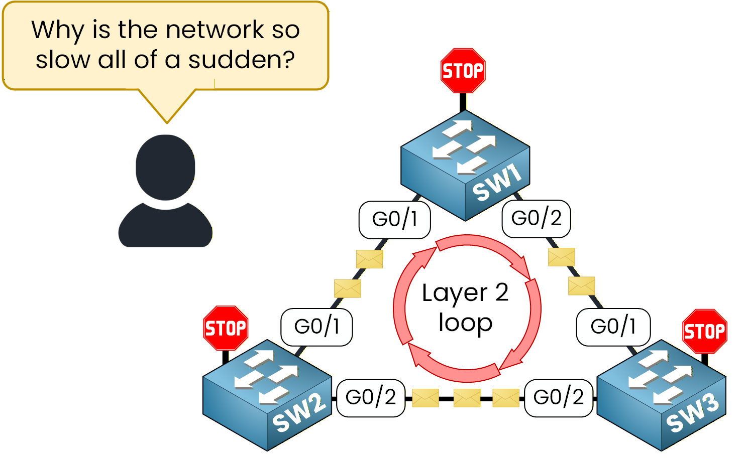
Figure 1 – Example of a Layer 2 loop created
What happened?
The network has fallen into a Layer 2 loop, a classic issue that can bring even simple Ethernet topologies to a halt. Frames endlessly circulate between switches because there’s no mechanism to stop them.
This is exactly the kind of disaster Spanning Tree Protocol (STP) was designed to prevent. STP ensures that even if multiple links exist between switches, only one logical path remains active. The others are placed in a blocking state to avoid loops but can reactivate instantly if a failure occurs.In this lab, you’ll learn how to configure the Spanning Tree Protocol and how to control which switch becomes the Root Bridge, the central decision-maker in any STP topology.
Network Topology Overview
Now that you understand why STP is necessary, let’s see how to configure it in practice.
Here is the topology you will use:SW1 as the Root Bridge
SW2 as the Backup Root Bridge
SW3 with its default priority, serving as a Non-Root Switch
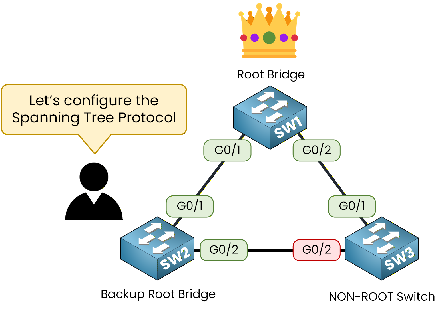
Figure 2 – Three-switch topology with Root, Backup, and Non-Root switches.
The term Backup Root Bridge may be new for you.
Don’t worry, in this lab, you’ll see exactly what it does and why we use it in an STP topology.Lab Overview
Here’s the structure we’ll follow throughout this lab:
Step 1 – Identify the current STP election
Step 2 – Configure SW1 as the Root Bridge
Step 3 – Configure SW2 as the Backup Root Bridge
Step 4 – Observe STP blocked linkLet’s Get Started
In the next sections, we’ll walk through each configuration step together, explain the commands, and verify that everything works correctly.
Answer the question below
Click 'Complete' to continue
These three switches are connected to each other. Even though we haven’t configured anything yet, STP is already running on all of them.
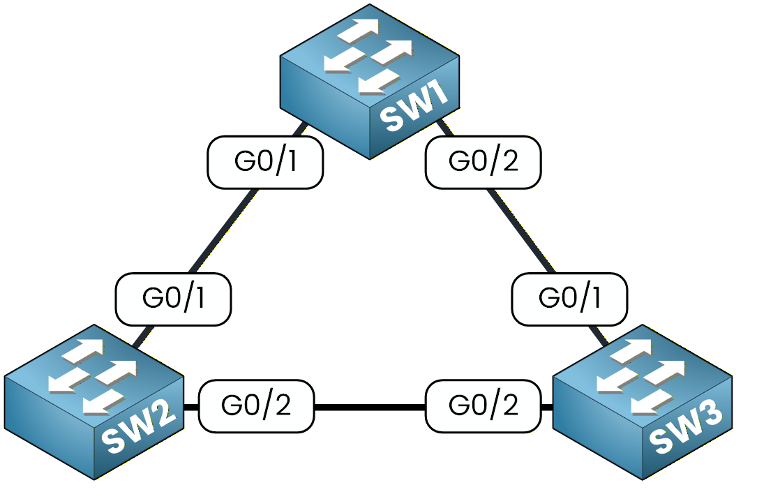
Figure 3 - Spanning Tree Topology
Your first goal is simple: observe how STP behaves by default and identify which switch is currently acting as the Root Bridge.
Let’s begin with SW1.
Check the Default Configuration
On SW1, enter the following command:
SW1# show running-config
Building configuration...

Current configuration : 1077 bytes
!
version 15.0
no service timestamps log datetime msec
no service timestamps debug datetime msec
no service password-encryption
!
hostname SW1
!
!
!
!
!
!
spanning-tree mode pvst
spanning-tree extend system-id
In the output, you will see the following lines:
spanning-tree mode pvst
spanning-tree extend system-id
As you can see, even before configuring anything, Cisco switches already have PVST enabled by default.
You might be asking yourself what PVST is, because we haven’t talked about it yet.What is PVST?
PVST, or Per VLAN Spanning Tree, is the default STP mode.
It creates one spanning tree instance per VLAN.
This means that if your network has multiple VLANs, you will have multiple spanning tree instances running.In our case, we only have VLAN 1, so we only have one instance of STP to look at.
Now let’s check how STP is behaving on this switch.
Type the following command:SW1# show spanning-tree ? active Report on active interfaces only detail Detailed information inconsistentports Show inconsistent ports interface Spanning Tree interface status and configuration summary Summary of port states vlan VLAN Switch Spanning Trees <cr>You will see several options.
We want to inspect VLAN 1, so run:SW1# show spanning-tree vlan 1 VLAN0001 Spanning tree enabled protocol ieee Root ID Priority 32769 Address 0001.63A6.E107 Cost 4 Port 25(GigabitEthernet0/1) Hello Time 2 sec Max Age 20 sec Forward Delay 15 sec Bridge ID Priority 32769 (priority 32768 sys-id-ext 1) Address 0060.7085.E6B0 Hello Time 2 sec Max Age 20 sec Forward Delay 15 sec Aging Time 20 Interface Role Sts Cost Prio.Nbr Type ---------------- ---- --- --------- -------- -------------------------------- Gi0/1 Root FWD 4 128.25 P2p Gi0/2 Desg FWD 4 128.26 P2pThere are several interesting elements here.
Let’s look at two of them.The Root ID section shows the information of the switch that STP has selected as the Root Bridge.
The Bridge ID section shows the information of the switch you are currently on, which is SW1.
You can see that the priority value is equal to the configured priority plus the system ID extension, which in this case is 1 because we are in VLAN 1.
At the bottom of the output, you can see the STP timers, but we will not discuss them now. You will learn about them in a later lesson.
Answer the question below
Which spanning-tree mode is enabled by default on a Cisco switch?
Now let’s look at SW2.
SW2# show spanning-tree vlan 1
VLAN0001
  Spanning tree enabled protocol ieee
  Root ID    Priority    32769
             Address     0001.63A6.E107
             This bridge is the root
             Hello Time  2 sec  Max Age 20 sec  Forward Delay 15 sec

  Bridge ID  Priority    32769  (priority 32768 sys-id-ext 1)
             Address     0001.63A6.E107
             Hello Time  2 sec  Max Age 20 sec  Forward Delay 15 sec
             Aging Time  20

Interface        Role Sts Cost      Prio.Nbr Type
---------------- ---- --- --------- -------- --------------------------------
Gi0/1            Desg FWD 4         128.25   P2p
Gi0/2            Desg FWD 4         128.26   P2p
Here, SW2 is the root bridge, as indicated by the message "This bridge is the root".
The Root ID and Bridge ID match, confirming that SW2 is currently controlling the spanning tree.
Next, let’s check SW3:SW3# show spanning-tree vlan 1 VLAN0001 Spanning tree enabled protocol ieee Root ID Priority 32769 Address 0001.63A6.E107 Cost 4 Port 26(GigabitEthernet0/2) Hello Time 2 sec Max Age 20 sec Forward Delay 15 sec Bridge ID Priority 32769 (priority 32768 sys-id-ext 1) Address 0090.2BE2.8EE9 Hello Time 2 sec Max Age 20 sec Forward Delay 15 sec Aging Time 20 Interface Role Sts Cost Prio.Nbr Type ---------------- ---- --- --------- -------- -------------------------------- Gi0/2 Root FWD 4 128.26 P2p Gi0/1 Altn BLK 4 128.25 P2pIn this output, you will notice something important.
One of the ports, Gi0/1, is in the Altn BLK state. This means the port is blocked.This behavior makes sense for our topology.
Because SW2 is the Root Bridge, STP must block one of the redundant links on the non-root switches.
On SW3, STP decided to block Gi0/1 to prevent a Layer 2 loop.This gives us the initial spanning tree topology, where SW2 is the Root Bridge.
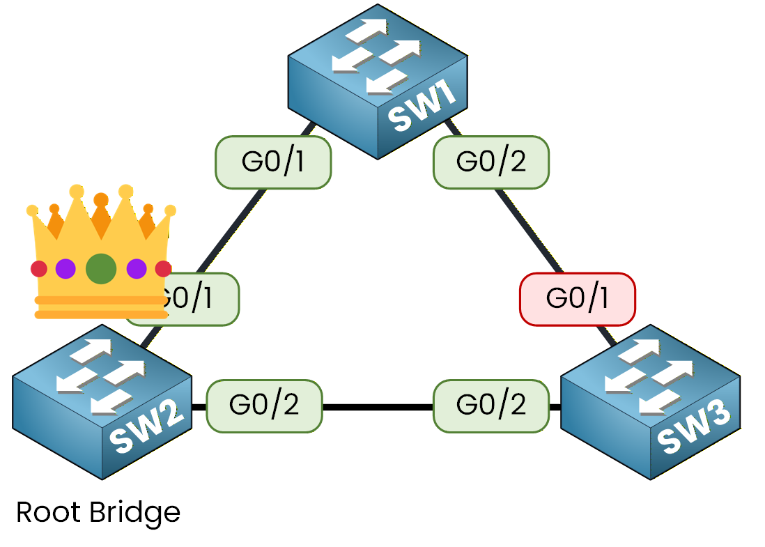
Figure 4 - Spanning Tree Initial Topology
At this point, STP has selected the Root Bridge automatically.
However, as a network engineer, you should be able to control which switch becomes the Root Bridge.
This is exactly what we will configure in Step 2.Answer the question below
On SW1, what is the priority value shown in the Bridge ID section?
In this section, we will ensure that SW1 becomes the root bridge, which is the central point from which the entire spanning tree topology is built. Let's review the root bridge election, after which we will go through the configuration.
Understanding the Root Bridge Election
In every STP topology, switches compare their Bridge ID (BID) to decide who will be the Root Bridge.
The BID is made up of two elements:.png)
Figure 5 – Spanning Tree Bridge ID Example
Bridge Priority
MAC Address
The switch with the lowest BID wins the election and takes the role of Root Bridge.
By default, every switch starts with a priority of32768 + VLAN ID.
That means any device could accidentally become the Root, leading to unpredictable traffic paths.
Let’s fix that by assigning a priority to SW1.Preparing to Configure the Root Bridge
To view what can be configured for VLAN 1:
SW1# conf t
Enter configuration commands, one per line.  End with CNTL/Z.
SW1(config)# spanning-tree vlan 1 ?
  forward-time  Set the forward delay for the spanning tree
  hello-time    Set the hello interval for the spanning tree
  max-age       Set the max age interval for the spanning tree
  priority      Set the bridge priority for the spanning tree
  root          Configure switch as root
Among these options, the key parameter is
priority, which determines who becomes the Root Bridge.Setting the Bridge Priority
The Bridge Priority defines how likely a switch is to be elected as the Root.
Cisco allows values between 0 and 61440, in increments of 4096.
The lower the number, the higher the chance of becoming Root Bridge.Priority Value
Description
0
Lowest possible value, almost guaranteed to become Root
4096
Very high priority
8192
High priority
12288–28672
Medium range
61440
Highest number, least likely to become Root
Table 1 - Spanning Tree Protocol Priority values
You could manually assign the lowest possible value like this:
SW1(config)# spanning-tree vlan 1 priority 0This would force SW1 to always win the election by giving it the lowest Bridge ID.
However, in our lab, we’ll use Cisco’s shortcut method.Using the Root Bridge Shortcut
Let’s now configure SW1 to become the Root Bridge using the shortcut command:
SW1(config)# spanning-tree vlan 1 root primary
SW1(config)# end
This command automatically adjusts the bridge priority so that SW1 becomes the Root Bridge for VLAN 1.
It’s simple, quick, and ensures the correct election outcome without manual calculations.Here’s how it works internally:
If no Root Bridge currently exists, the command sets the priority to
24576 + VLAN ID.If another Root Bridge is already active, it
reduces SW1’s priority by 4096, ensuring this switch takes over as Root.
In both cases, SW1 ends up with the lowest effective Bridge ID, guaranteeing that it becomes the Root Bridge in the topology.
Verifying the Configuration
After applying the command, let’s confirm that SW1 is now acting as the Root Bridge.
Use the following command to display the STP status for VLAN 1:SW1# show spanning-tree VLAN0001 Spanning tree enabled protocol ieee Root ID Priority 24577 Address 0007.EC4E.DE9C This bridge is the root Hello Time 2 sec Max Age 20 sec Forward Delay 15 sec Bridge ID Priority 24577 (priority 24576 sys-id-ext 1) Address 0007.EC4E.DE9C Hello Time 2 sec Max Age 20 sec Forward Delay 15 sec Aging Time 20 Interface Role Sts Cost Prio.Nbr Type ---------------- ---- --- --------- -------- -------------------------------- Gi0/2 Desg FWD 4 128.26 P2p Gi0/1 Desg FWD 4 128.25 P2pNow, let’s analyze the output.
The line “This bridge is the root” confirms that SW1 has successfully become the Root Bridge for VLAN 1.
The Root ID and Bridge ID are identical, which means this switch is the central reference point for the STP topology.
Your configuration is now complete: SW1 has taken the Root Bridge role, and all other switches in the network will recognize it as the main decision point for path calculation.
Answer the question below
State the message in the output that confirms SW1 is acting as the Root Bridge.
Now that SW1 is configured as the Root Bridge, let’s make sure the network stays stable even if it goes down.
We’ll configure SW2 as the Backup Root Bridge, so it can automatically take over in case of failure.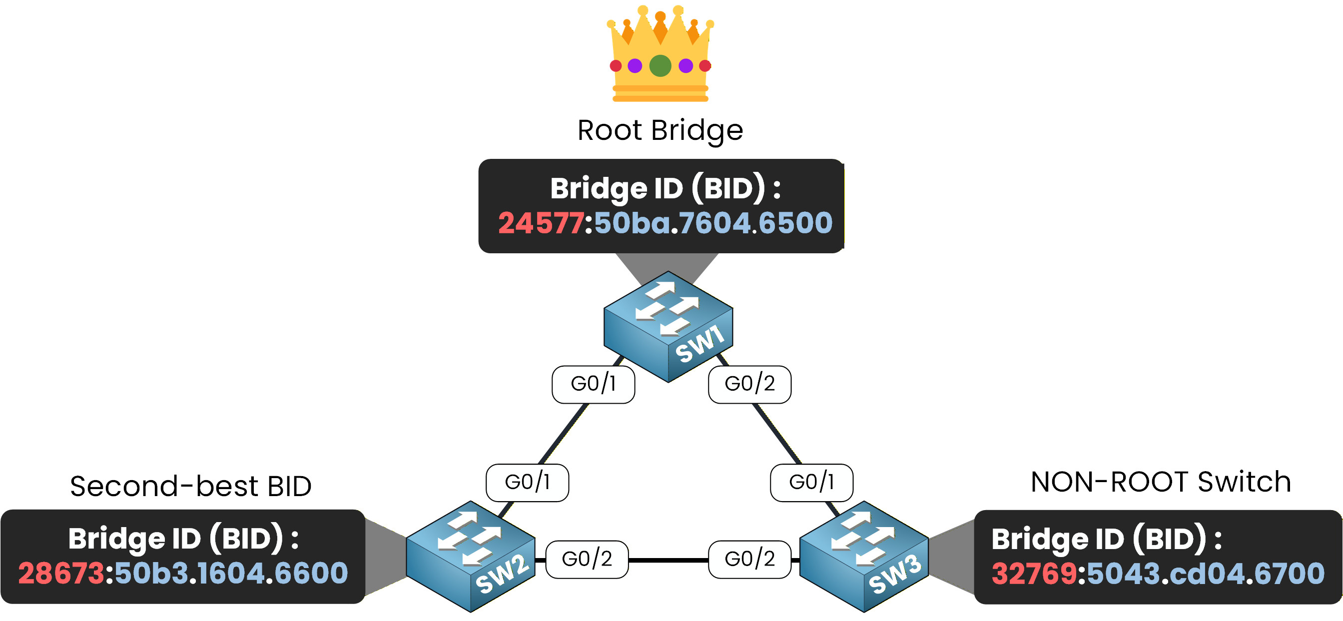
Figure 6 – Three-switch topology with Root, Backup, and Non-Root switches.
Why Configure a Backup Root Bridge
When the Root Bridge becomes unavailable, STP launches a new election.
If no priorities are predefined, any switch could be selected as the new Root, even one that isn’t optimally placed in the network.By defining a Backup Root Bridge, we make this process predictable.
If SW1 fails, SW2 will immediately take over as the new Root Bridge, maintaining the same topology and keeping the network stable.Setting SW2 as the Backup Root Bridge
To configure SW2 as the backup, use the following command:
SW2(config)# spanning-tree vlan 1 root secondary
SW2(config)# end
That’s it: the switch is now ready to serve as a backup Root Bridge.
Theroot secondarycommand automatically sets a lower priority than the default value but still higher than the Root Bridge. This way, SW2 never competes with SW1 while it’s active but can instantly take control if SW1 goes down.Internally, the command assigns a
priority of 28672 + VLAN ID, which is lower than the default 32768 + VLAN ID, yet higher than the Root’s 24576 + VLAN ID.Verifying SW2 Configuration
After applying the command, verify that SW2 correctly recognizes SW1 as the Root Bridge and is positioned as the backup:
SW2# show spanning-tree vlan 1
VLAN0001
  Spanning tree enabled protocol ieee
  Root ID    Priority    24577
             Address     0007.EC4E.DE9C
             Cost        4
             Port        25(GigabitEthernet0/1)
             Hello Time  2 sec  Max Age 20 sec  Forward Delay 15 sec

  Bridge ID  Priority    28673  (priority 28672 sys-id-ext 1)
             Address     0002.169E.4B47
             Hello Time  2 sec  Max Age 20 sec  Forward Delay 15 sec
             Aging Time  20

Interface        Role Sts Cost      Prio.Nbr Type
---------------- ---- --- --------- -------- --------------------------------
Gi0/1            Root FWD 4         128.25   P2p
Gi0/2            Desg FWD 4         128.26   P2p
The Root ID confirms that SW1 is the active Root Bridge.
The Bridge ID of SW2 displays its adjusted priority value of28672 + VLAN ID, confirming that it’s configured as the Backup Root Bridge and ready to take over if needed.
Answer the question below
What is the Bridge ID of SW2?
Now that the Root and Backup Root Bridges are configured, let’s check how the remaining switch, SW3, behaves in the topology after the STP election.
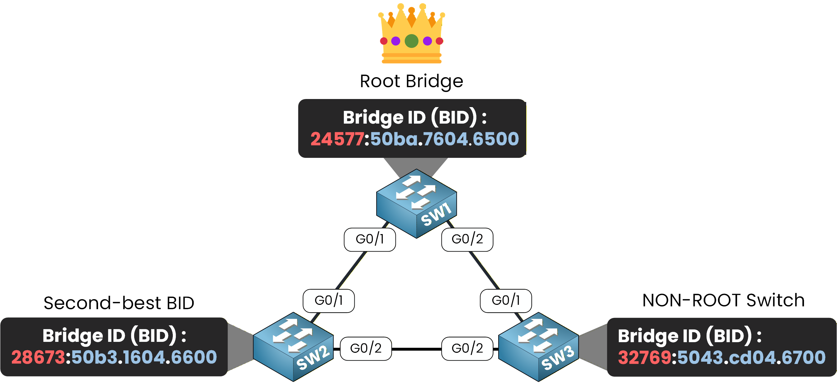
Figure 7 – STP priority verification showing Root, Backup, and Non-Root switches with their Bridge IDs.
Verifying on SW3 (Non-Root Switch)
To confirm that SW3 correctly recognizes SW1 as the Root Bridge and has kept its default settings, use:
SW3# show spanning-tree vlan 1
VLAN0001
  Spanning tree enabled protocol ieee
  Root ID    Priority    24577
             Address     0007.EC4E.DE9C
             Cost        4
             Port        25(GigabitEthernet0/1)
             Hello Time  2 sec  Max Age 20 sec  Forward Delay 15 sec

  Bridge ID  Priority    32769  (priority 32768 sys-id-ext 1)
             Address     00D0.BC65.C145
             Hello Time  2 sec  Max Age 20 sec  Forward Delay 15 sec
             Aging Time  20

Interface        Role Sts Cost      Prio.Nbr Type
---------------- ---- --- --------- -------- --------------------------------
Gi0/2            Altn BLK 4         128.26   P2p
Gi0/1            Root FWD 4         128.25   P2p
By default, Spanning Tree Protocol (STP) is enabled on all Cisco switches.
Since SW3’s priority wasn’t modified, it automatically joins the STP process using its default Bridge Priority (32768 + VLAN ID).SW3 correctly identifies SW1 as the Root Bridge and keeps its default priority, confirming that it’s acting as a Non-Root Switch in the topology.
STP in Action
In this output, STP automatically placed one of SW3’s ports into a blocking state.
This behavior prevents a potential Layer 2 loop while keeping an alternate path ready in case a link fails.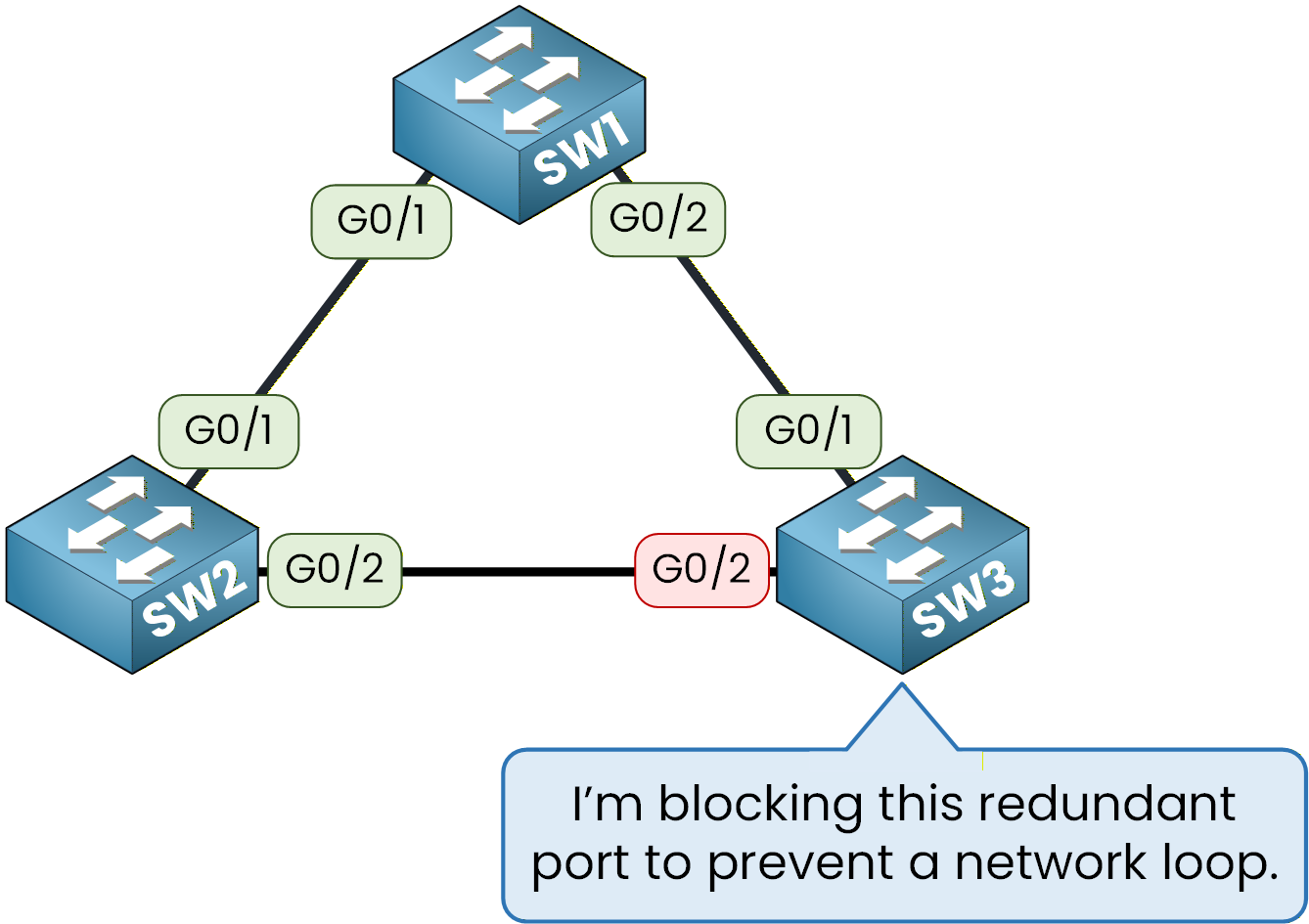
Figure 8 – SW3 blocks a redundant port to keep the network loop-free.
It confirms that the spanning tree is working as intended:
SW1 controls the topology, SW2 stands ready as backup, and SW3 dynamically adapts to maintain a stable, loop-free network.Answer the question below
Go to the SW3 output and look at the Interface column. Give the name of the interface that is in the blocking state.
You’ve now completed the first step of the Spanning Tree Protocol, electing the Root Bridge.
SW1 has been configured as the Root Bridge, and SW2 as the Backup Root Bridge, ensuring that the topology remains predictable and stable.At this stage, STP is fully active.
It automatically blocked one redundant port on SW3 to prevent a loop, while keeping an alternate path available in case of a link failure.So far, we’ve seen how STP selects the Root Bridge (step 1) and how it maintains loop prevention by blocking redundant links (step 4).
However, we haven’t yet explained how the protocol decides which ports forward traffic and which ports stay blocked.What’s Next?
In the next lesson, we’ll explore the missing steps of the Spanning Tree process:
Elect the Root Bridge
Identify Root Ports
Determine Designated Ports
Assign Blocked Ports
Understanding Spanning Tree Port Roles will allow you to see exactly how STP builds a loop-free topology while keeping network redundancy intact.
Answer the question below
Click 'Complete' to continue