In MST Fundamentals you designed two instances with two different roots, so that every uplink carries traffic.
Time to make it real on the three switches.The Topology
Same triangle as before: SW1, SW2 and SW3, three 1 Gbps trunks, four department VLANs.
SW1 is a pure transit switch. SW2 hosts Finance and HR, SW3 hosts Engineering and Sales.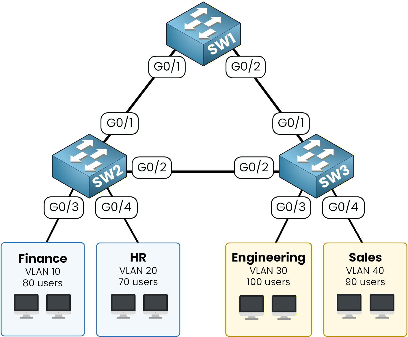
Figure 1 – MST lab network diagram
Here is the plan you will follow:
Enable MST mode on SW1, SW2 and SW3
Build the region: name, revision, instance mapping
Elect a root per instance and verify the topology
Read the blocked ports, then fix the root you never chose
The four VLANs and the trunks are already configured on the three switches.
Everything you type in this lesson is spanning tree only.If you need a refresher on VLANs and 802.1Q trunks, see the CCNA Spanning Tree lab.
Answer the question below
Read the topology, then type Complete.
Check the Current STP Mode
Before changing anything, read the mode SW1 runs today:
SW1# show spanning-tree summary
Switch is in pvst mode
Root bridge for: none
Extended system ID                      is enabled
Portfast Default                        is disabled
Portfast Edge BPDU Guard Default        is disabled
Portfast Edge BPDU Filter Default       is disabled
Loopguard Default                       is disabled
PVST Simulation Default                 is enabled but inactive in pvst mode
Bridge Assurance                        is enabled but inactive in pvst mode
EtherChannel misconfig guard            is enabled
Configured Pathcost method used is short
UplinkFast                              is disabled
BackboneFast                            is disabled

Name                   Blocking Listening Learning Forwarding STP Active
---------------------- -------- --------- -------- ---------- ----------
VLAN0001                     1         0        0          7          8
VLAN0010                     1         0        0          1          2
VLAN0020                     1         0        0          1          2
VLAN0030                     1         0        0          1          2
VLAN0040                     1         0        0          1          2
---------------------- -------- --------- -------- ---------- ----------
5 vlans                      5         0        0         11         16
SW1 runs in PVST+ mode, with five separate trees and one blocking port in each of them.
The same applies to SW2 and SW3.Switch SW1 to MST Mode
The mode change is a single global command:
SW1# configure terminal
SW1(config)# spanning-tree mode mst
SW1(config)# end
Read the summary again to confirm the change:
SW1# show spanning-tree summary
Switch is in mst mode (IEEE Standard)
Root bridge for: none
Extended system ID                      is enabled
Portfast Default                        is disabled
Portfast Edge BPDU Guard Default        is disabled
Portfast Edge BPDU Filter Default       is disabled
Loopguard Default                       is disabled
PVST Simulation                         is enabled
Bridge Assurance                        is enabled
EtherChannel misconfig guard            is enabled
Configured Pathcost method used is short (Operational value is long)
UplinkFast                              is disabled
BackboneFast                            is disabled

Name                   Blocking Listening Learning Forwarding STP Active
---------------------- -------- --------- -------- ---------- ----------
MST0                         0         0        6          2          8
---------------------- -------- --------- -------- ---------- ----------
1 mst                        0         0        6          2          8
SW1 now runs MST, and the output names the IEEE standard behind it.
Five trees became one: MST0, the IST you met in the previous lesson. Your ports are in learning state because the tree is converging.Switch SW2 and SW3 to MST Mode
Apply the same change on SW2 and SW3, so all three speak the same protocol:
SW2# configure terminal
SW2(config)# spanning-tree mode mst
SW2(config)# end

SW3# configure terminal
SW3(config)# spanning-tree mode mst
SW3(config)# end
All three switches now run MST, but they only share instance 0.
Each one still uses the default region settings: an empty name, revision 0, and every VLAN in instance 0.
That is what you fix next.Answer the question below
After the mode change, how many spanning trees does SW1 run?
Three values must match on every switch of a region: name, revision, and VLAN-to-instance mapping.
You set them in a dedicated configuration sub-mode.Name, Revision and Mapping on SW1
Enter the MST configuration sub-mode and define the region:
SW1# configure terminal
SW1(config)# spanning-tree mst configuration
SW1(config-mst)# name PMN
SW1(config-mst)# revision 1
SW1(config-mst)# instance 1 vlan 10,20
SW1(config-mst)# instance 2 vlan 30,40
SW1(config-mst)# end
Three things happened on SW1:
The region name was set to
PMNand the revision to1VLANs 10 and 20 were mapped to MST instance 1
VLANs 30 and 40 were mapped to MST instance 2
One detail matters here. Nothing is applied while you type inside
(config-mst)#.
The whole block is committed when you leave the sub-mode, which is whyendis part of the configuration, not a formality.Verify the Region
Read the region back before copying it anywhere:
SW1# show spanning-tree mst configuration
Name      [PMN]
Revision  1     Instances configured 3

Instance  Vlans mapped
--------  ---------------------------------------------------------------------
0         1-9,11-19,21-29,31-39,41-4094
1         10,20
2         30,40
-------------------------------------------------------------------------------
The output confirms region PMN with revision 1, and the three instances.
You configured two. Instance 0 is there anyway, holding every VLAN you did not map, exactly as the previous lesson said.Answer the question below
How many instances does SW1 report as configured?
Replicate on SW2 and SW3
The region parameters must be identical on every switch.
Apply the exact same block on SW2 and SW3. One character off in the name, or a different revision, and that switch leaves the region:SW2# configure terminal SW2(config)# spanning-tree mst configuration SW2(config-mst)# name PMN SW2(config-mst)# revision 1 SW2(config-mst)# instance 1 vlan 10,20 SW2(config-mst)# instance 2 vlan 30,40 SW2(config-mst)# end SW3# configure terminal SW3(config)# spanning-tree mst configuration SW3(config-mst)# name PMN SW3(config-mst)# revision 1 SW3(config-mst)# instance 1 vlan 10,20 SW3(config-mst)# instance 2 vlan 30,40 SW3(config-mst)# endAll three switches now share region PMN, revision 1, with VLANs 10/20 in instance 1 and VLANs 30/40 in instance 2.
They can finally exchange BPDUs as members of the same region.Answer the question below
Which MST instance automatically holds every unmapped VLAN?
MST is active and the region is shared. But right now, the root of each instance was elected automatically, on the lowest Bridge ID.
As the engineer, you should control which switch is the root for each instance.Plan the Roots
Here is the plan for your two instances:
MST 1 (VLANs 10, 20): SW1 root primary, SW2 root secondary
MST 2 (VLANs 30, 40): SW2 root primary, SW1 root secondary
SW3 keeps the default priority on both instances
This split shares the root role between SW1 and SW2, so neither switch handles all traffic.
If one of them fails, the other takes over for that instance.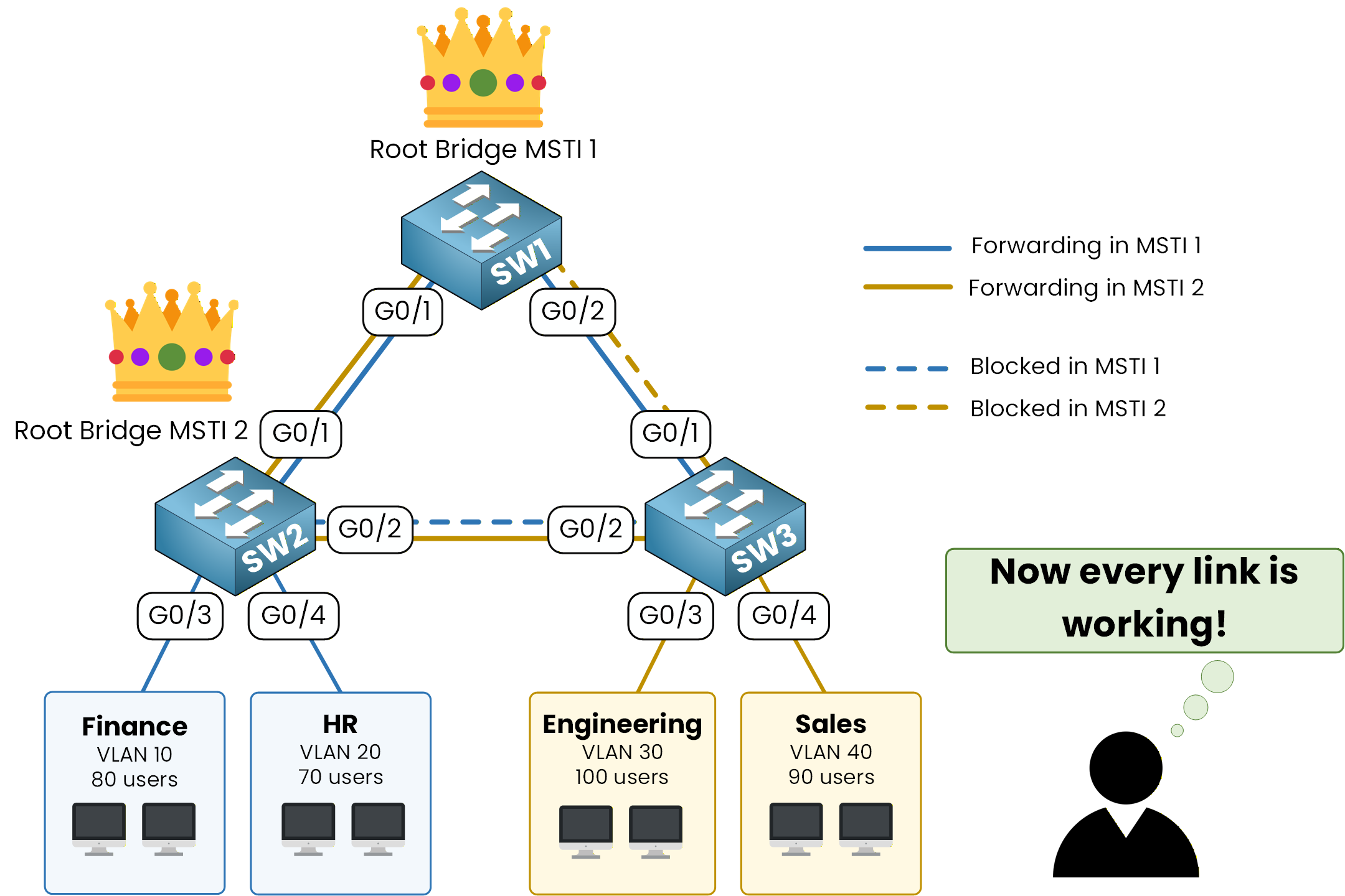
Figure 2 – Recall: one root per instance, every uplink used
Root Primary and Secondary per Instance
Use the
root primaryandroot secondaryshortcuts you know from the STP lab. They work the same way on MST instances.
Start with SW1:SW1# configure terminal SW1(config)# spanning-tree mst 1 root primary SW1(config)# spanning-tree mst 2 root secondary SW1(config)# endNow the mirrored configuration on SW2:
SW2# configure terminal
SW2(config)# spanning-tree mst 2 root primary
SW2(config)# spanning-tree mst 1 root secondary
SW2(config)# end
SW1 is primary for MST 1 and secondary for MST 2. SW2 is the exact mirror.
SW3 keeps its default priority on both instances and stays a non-root switch.Verify MST 1 and MST 2
Confirm that SW1 is the root for instance 1:
SW1# show spanning-tree mst 1
##### MST1    vlans mapped:   10,20
Bridge        address 5094.f800.4300  priority      24577 (24576 sysid 1)
Root          this switch for MST1

Interface        Role Sts Cost      Prio.Nbr Type
---------------- ---- --- --------- -------- --------------------------------
Gi0/1            Desg FWD 20000     128.2    P2p
Gi0/2            Desg FWD 20000     128.3    P2p
Two lines confirm the result.
Root this switch for MST1tells you SW1 is the root, and the priority 24576 plus the instance number is what the root primary shortcut applies.
Both Gi0/1 and Gi0/2 are designated forwarding ports, exactly what you expect on a root.
Now check MST 2 from SW2:SW2# show spanning-tree mst 2 ##### MST2 vlans mapped: 30,40 Bridge address 500a.b600.4400 priority 24578 (24576 sysid 2) Root this switch for MST2 Interface Role Sts Cost Prio.Nbr Type ---------------- ---- --- --------- -------- -------------------------------- Gi0/1 Desg FWD 20000 128.2 P2p Gi0/2 Desg FWD 20000 128.3 P2pSW2 is the root for MST 2, both trunks designated forwarding.
The two instances now have different roots, which is what you came for.Answer the question below
What base priority does the root primary shortcut apply to an MST instance?
Two instances, two roots. The real test is SW3, the switch that is root of nothing.
Read what MST decided on its trunks, then on one trunk of SW1, where a surprise waits.The Blocked Ports on SW3
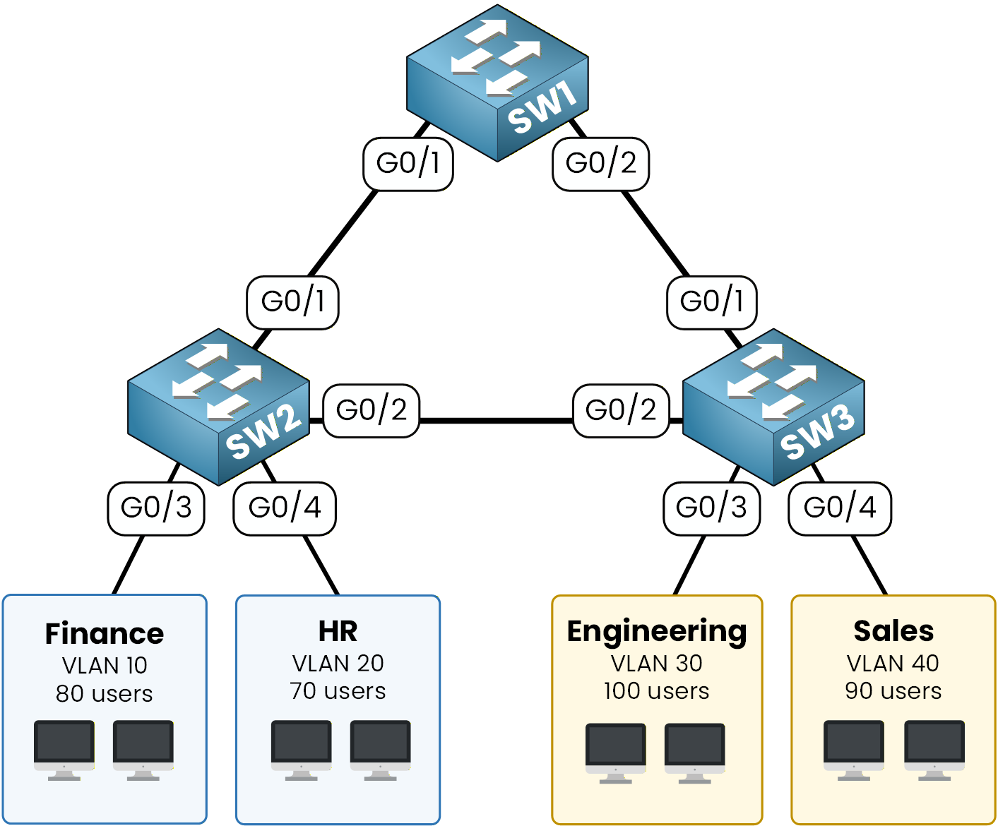
Figure 3 – Recall: SW3 Gi0/1 toward SW1, Gi0/2 toward SW2
SW3 is non-root on both instances, so MST must block one of its two trunks per instance to break the loop.
Read all instances at once:SW3# show spanning-tree mst ##### MST0 vlans mapped: 1-9,11-19,21-29,31-39,41-4094 Bridge address 5068.5d00.4500 priority 32768 (32768 sysid 0) Root address 500a.b600.4400 priority 32768 (32768 sysid 0) port Gi0/2 path cost 0 Regional Root address 500a.b600.4400 priority 32768 (32768 sysid 0) internal cost 20000 rem hops 19 Operational hello time 2 , forward delay 15, max age 20, txholdcount 6 Configured hello time 2 , forward delay 15, max age 20, max hops 20 Interface Role Sts Cost Prio.Nbr Type ---------------- ---- --- --------- -------- -------------------------------- Gi0/1 Desg FWD 20000 128.2 P2p Gi0/2 Root FWD 20000 128.3 P2p ##### MST1 vlans mapped: 10,20 Bridge address 5068.5d00.4500 priority 32769 (32768 sysid 1) Root address 5094.f800.4300 priority 24577 (24576 sysid 1) port Gi0/1 cost 20000 rem hops 19 Interface Role Sts Cost Prio.Nbr Type ---------------- ---- --- --------- -------- -------------------------------- Gi0/1 Root FWD 20000 128.2 P2p Gi0/2 Altn BLK 20000 128.3 P2p ##### MST2 vlans mapped: 30,40 Bridge address 5068.5d00.4500 priority 32770 (32768 sysid 2) Root address 500a.b600.4400 priority 24578 (24576 sysid 2) port Gi0/2 cost 20000 rem hops 19 Interface Role Sts Cost Prio.Nbr Type ---------------- ---- --- --------- -------- -------------------------------- Gi0/1 Altn BLK 20000 128.2 P2p Gi0/2 Root FWD 20000 128.3 P2pLook at the two custom instances on SW3:
On MST 1, Gi0/1 is the root port toward SW1, and Gi0/2 is
Altn BLK, blocked toward SW2On MST 2, Gi0/2 is the root port toward SW2, and Gi0/1 is
Altn BLK, blocked toward SW1
This is the load-sharing benefit of MST.
On SW3, each instance blocks a different port, so the link to SW1 carries VLANs 10/20 and the link to SW2 carries VLANs 30/40.
Both uplinks of SW3 forward user traffic. Keep the MST0 block of this output in mind: you will come back to it in a minute.Answer the question below
On SW3, which port is blocked for MST 1?
The Surprise on SW1
So far you read the topology one instance at a time.
In production you usually start from the other side, withshow spanning-tree mst interface: one trunk, and what every instance does with it. Take Gi0/2 on SW1, the trunk toward SW3:SW1# show spanning-tree mst interface g0/2 GigabitEthernet0/2 of MST0 is alternate blocking Portfast : no (default) port guard : none (default) Link type: point-to-point (auto) bpdu filter: disable (default) Boundary : internal bpdu guard : disable (default) PVST Sim : enable (default) Bpdus sent 137, received 153 Instance Role Sts Cost Prio.Nbr Vlans mapped -------- ---- --- --------- -------- ------------------------------- 0 Altn BLK 20000 128.3 1-9,11-19,21-29,31-39,41-4094 1 Desg FWD 20000 128.3 10,20 2 Desg FWD 20000 128.3 30,40Two things to read here.
TheBoundary : internalline says the neighbor on this port belongs to the same region. If SW3 had a different name or revision, you would readboundaryinstead, and this is the fastest way to catch a region split.
Then the table, one role per instance on the same physical port. For MST 1 and MST 2, SW1 is either the root or the secondary root, so Gi0/2 forwards downstream to SW3. Good.For MST 0, Gi0/2 is
Altn BLK. SW1 reaches the instance 0 root through Gi0/1, so the path through SW3 would be a loop and is blocked.
SW1, the switch you wanted at the top of the design, is blocking a port. On an instance you never planned.
Run the same command on the two trunks of SW3 and you get the mirror of the previous output: instance 1 forwards on Gi0/1, instance 2 on Gi0/2. That part works as designed.The Root You Forgot
Back to instance 0.
In the SW3 output above, the MST0 root address was 500a.b600.4400, with priority 32768. That is SW2, and it won because it has the lowest MAC address of the three.
SW2 is the root of VLAN 1, your management VLAN, and of 4089 other VLANs, and nobody chose it. Replace SW2 next year with a switch that has a lower MAC, and the IST root moves by itself.Instance 0 gets a root like any other. Give it to SW1, so the IST follows the same design as instance 1:
SW1# configure terminal
SW1(config)# spanning-tree mst 0 root primary
SW1(config)# end
Verify instance 0 from SW1:
SW1# show spanning-tree mst 0
##### MST0    vlans mapped:   1-9,11-19,21-29,31-39,41-4094
Bridge        address 5094.f800.4300  priority      24576 (24576 sysid 0)
Root          this switch for the CIST
Operational   hello time 2 , forward delay 15, max age 20, txholdcount 6
Configured    hello time 2 , forward delay 15, max age 20, max hops    20

Interface        Role Sts Cost      Prio.Nbr Type
---------------- ---- --- --------- -------- --------------------------------
Gi0/1            Desg FWD 20000     128.2    P2p
Gi0/2            Desg FWD 20000     128.3    P2p
SW1 is now the root of instance 0, and both of its trunks are designated forwarding again.
The output saysCISTrather than MST0: the Common and Internal Spanning Tree is the single tree that spans every region. With one region, it is your IST.
Three instances, three roots you chose, every uplink forwarding. The design you planned in Figure 2 is now running on real switches.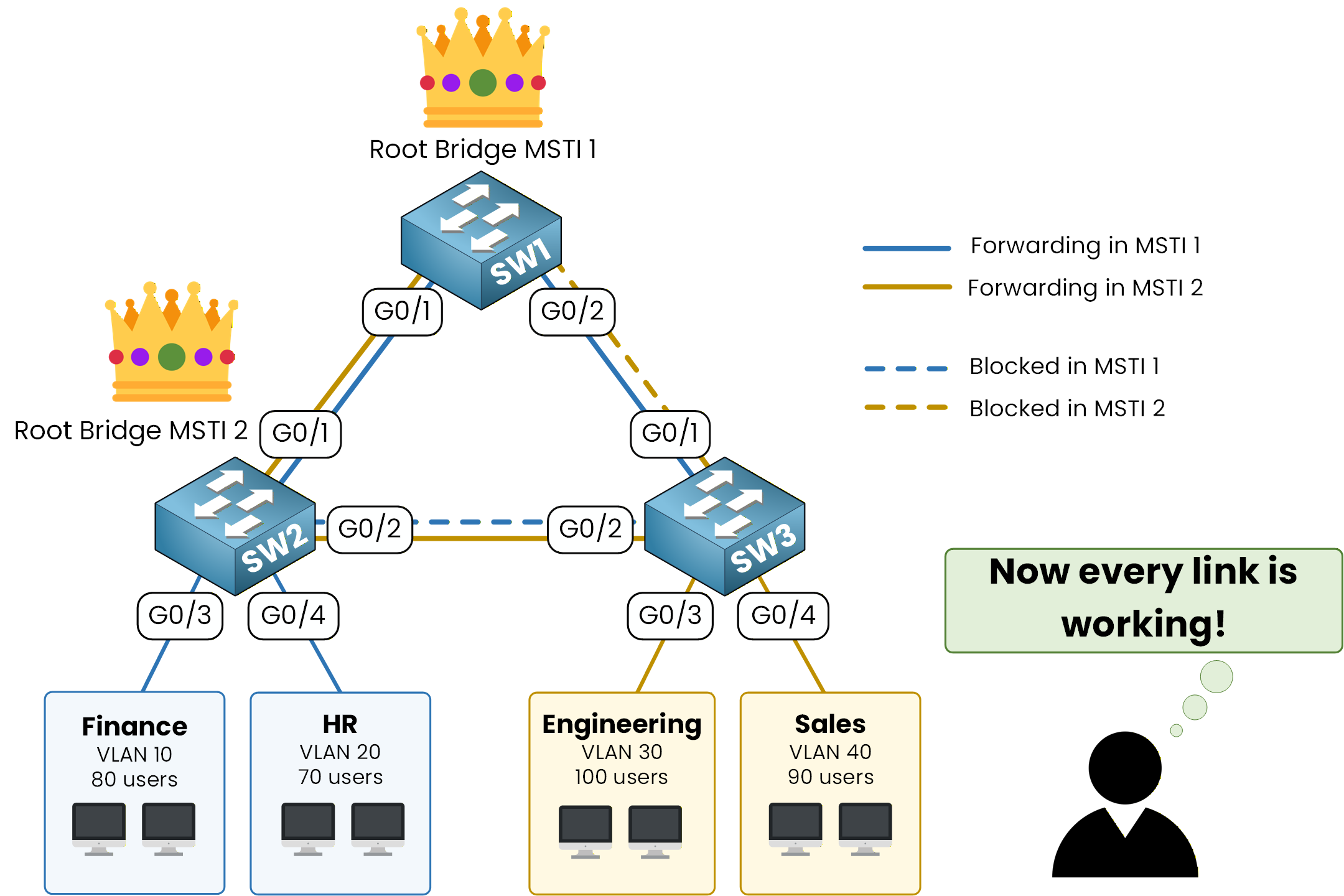
Figure 4 – Every uplink forwarding, as designed
Next comes the lab, where you build a region from a blank console, with no command written under the task.
Answer the question below
After the fix, which switch is the root of instance 0?
Answer the question below
Before mst 0 root primary on SW1, which switch becomes IST root if SW2 fails?