Multiple Spanning Tree (MST), defined in IEEE 802.1s and now part of 802.1Q, is a Layer 2 protocol that lets you group several VLANs into one spanning tree instance.
Before seeing how it works, you need to feel the problem it solves on a real enterprise network.The Network You Inherited
You are the network engineer of a mid-sized company.
Three distribution switches (SW1, SW2 and SW3) carry every VLAN of the business.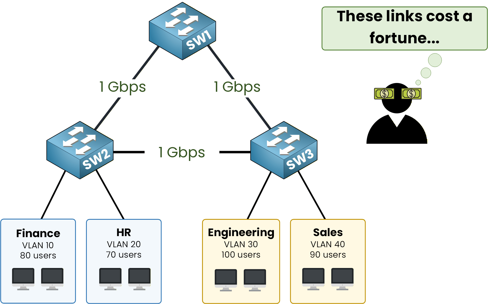
Figure 1 – Triangle links, four VLANs
Behind them sit four departments: Finance and HR on VLAN 10 and 20, Engineering and Sales on VLAN 30 and 40.
The three switches are wired in a full triangle with three 1 Gbps uplinks.
The company paid for that redundancy, so all three links should carry traffic. You will see in a moment that classic spanning tree wastes one of them.Answer the question below
Read the topology, then type Complete.
Per-VLAN Architecture in Rapid-PVST+
By default, Cisco switches run a Per-VLAN Spanning Tree (PVST+ or Rapid-PVST+), where a dedicated STP instance is maintained for every configured VLAN.
Four user VLANs give you four distinct, independent spanning tree topologies.
Each tree elects a root bridge with the same rule: lowest Bridge ID wins.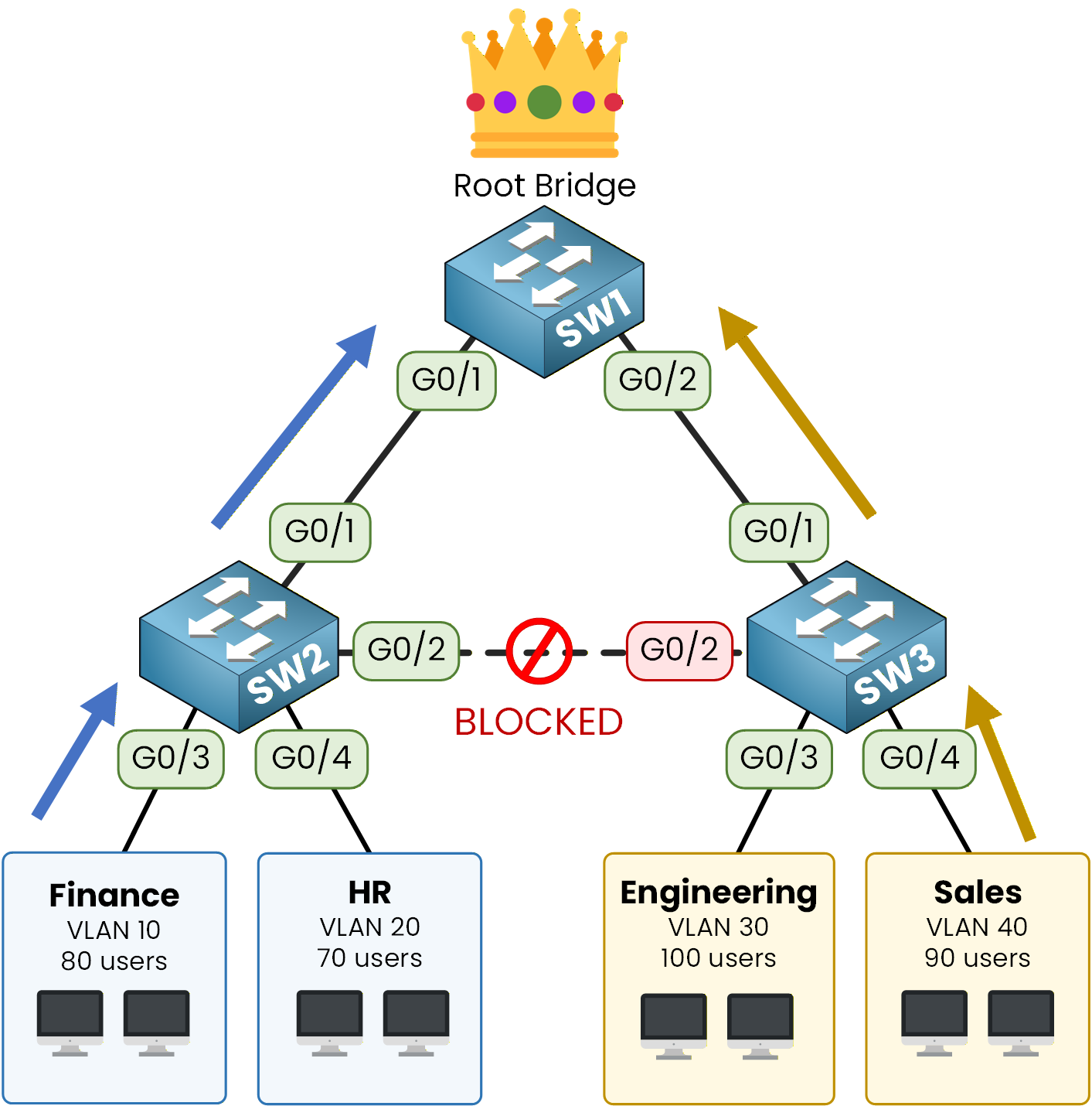
Figure 2 – All VLANs toward SW1
All your switches keep the default priority of 32768, so the switch with the lowest MAC address is elected. Say it is SW1.
The four trees all pick the same root.
And if four trees have the same root, they all block the same redundant link to prevent loops.One Uplink, Zero Packets
The link between SW2 and SW3 is now blocked for every VLAN.
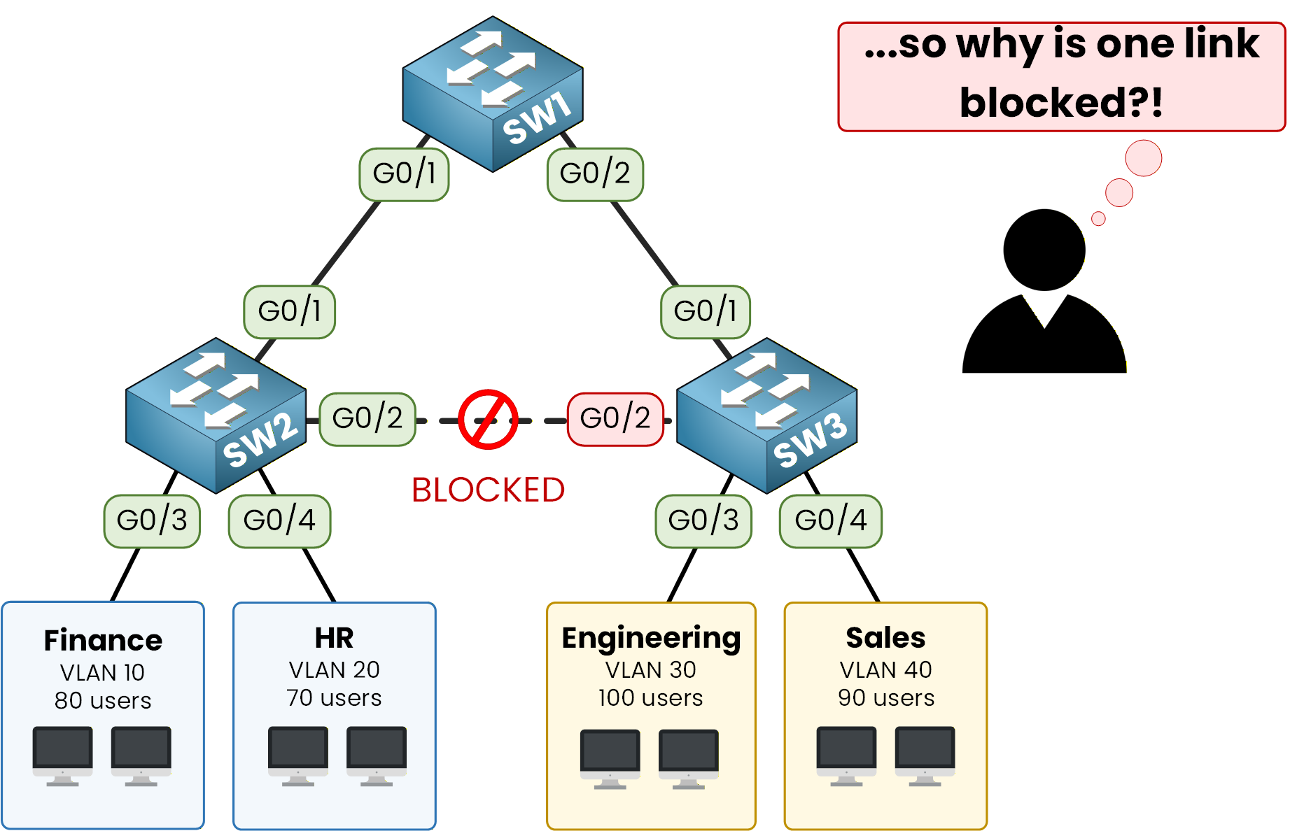
Figure 3 – SW2-SW3 link blocked (PVST+)
One of your three 1 Gbps uplinks carries zero packets.
The company paid for redundancy and capacity, and Rapid-PVST+ only gives you redundancy.
You could fix this by hand, with a different root priority on each of the four VLANs.
But that means four trees to tune, four sets of BPDUs on every trunk, and four topologies to troubleshoot. With 200 VLANs, it is 200 of everything.Answer the question below
In Rapid-PVST+, how many spanning tree instances run when you have 4 VLANs?
MST groups several VLANs into a single spanning tree, so you end up with fewer instances to manage.
The real benefit comes from choosing a different root bridge per instance, which is what unlocks load-balancing across your uplinks.One Instance, Several VLANs
An MST instance (MSTI) is one spanning tree that carries a list of VLANs you assign to it.
On current Catalyst switches, instance numbers go from 1 to 4094.
For your network, two are enough:MSTI 1 carries VLAN 10 and 20, with SW1 as root.
MSTI 2 carries VLAN 30 and 40, with SW2 as root.
Two instances instead of four trees. And each instance gets its own root, which is the part that matters.
MSTI 1: Finance and HR Toward SW1
Start with MSTI 1. VLAN 10 (Finance) and VLAN 20 (HR) are mapped to this instance, and SW1 is the root bridge.
Every Finance or HR frame climbs toward SW1.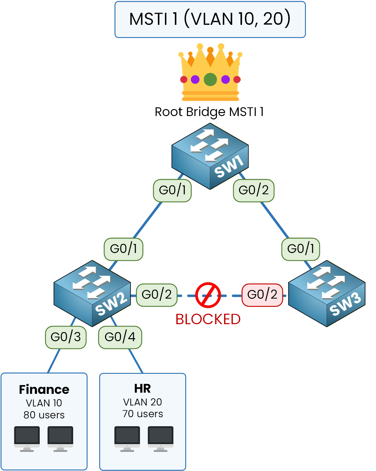
Figure 4 – MSTI 1: VLANs 10-20
When a Finance user sends a packet, it rides the blue path from SW2, up to SW1 via G0/1.
The G0/2 trunk between SW2 and SW3 stays blocked for MSTI 1 only.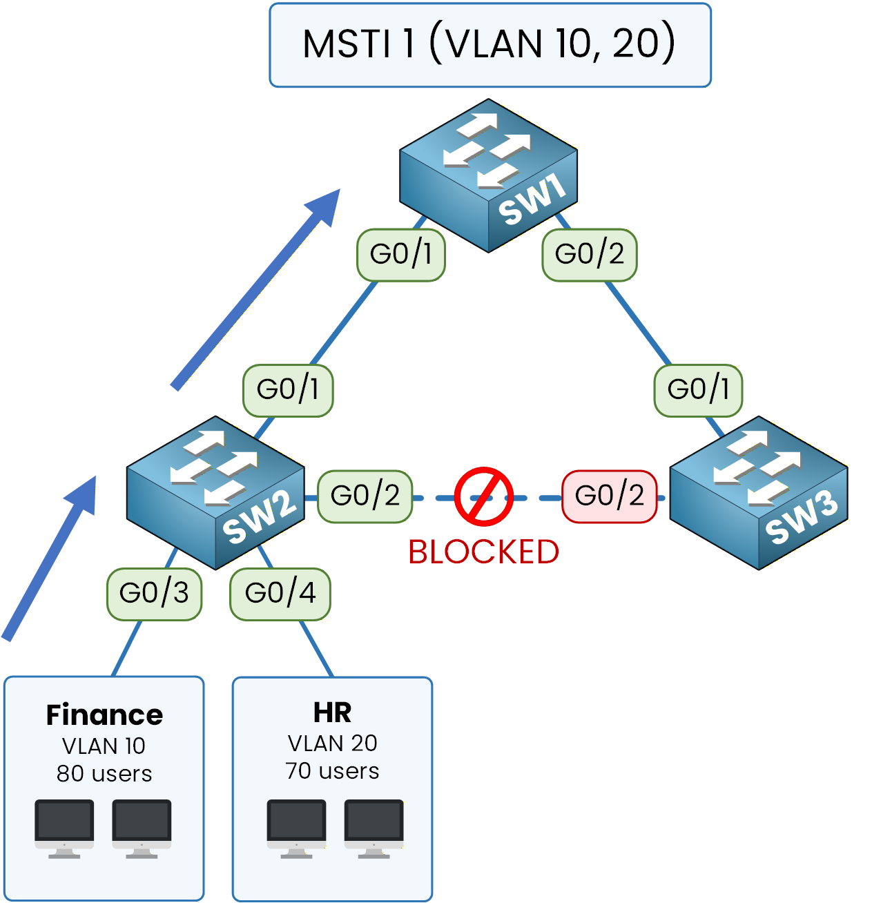
Figure 5 – MSTI 1: Forwarding toward SW1
So far this looks exactly like the PVST+ picture. Same root, same blocked link.
The difference appears with the second instance.Answer the question below
Which instance carries VLAN 30 and 40?
MSTI 2: Engineering and Sales Toward SW2
Now look at MSTI 2. VLAN 30 (Engineering) and VLAN 40 (Sales) are mapped to this instance, but this time SW2 is the root, not SW1.
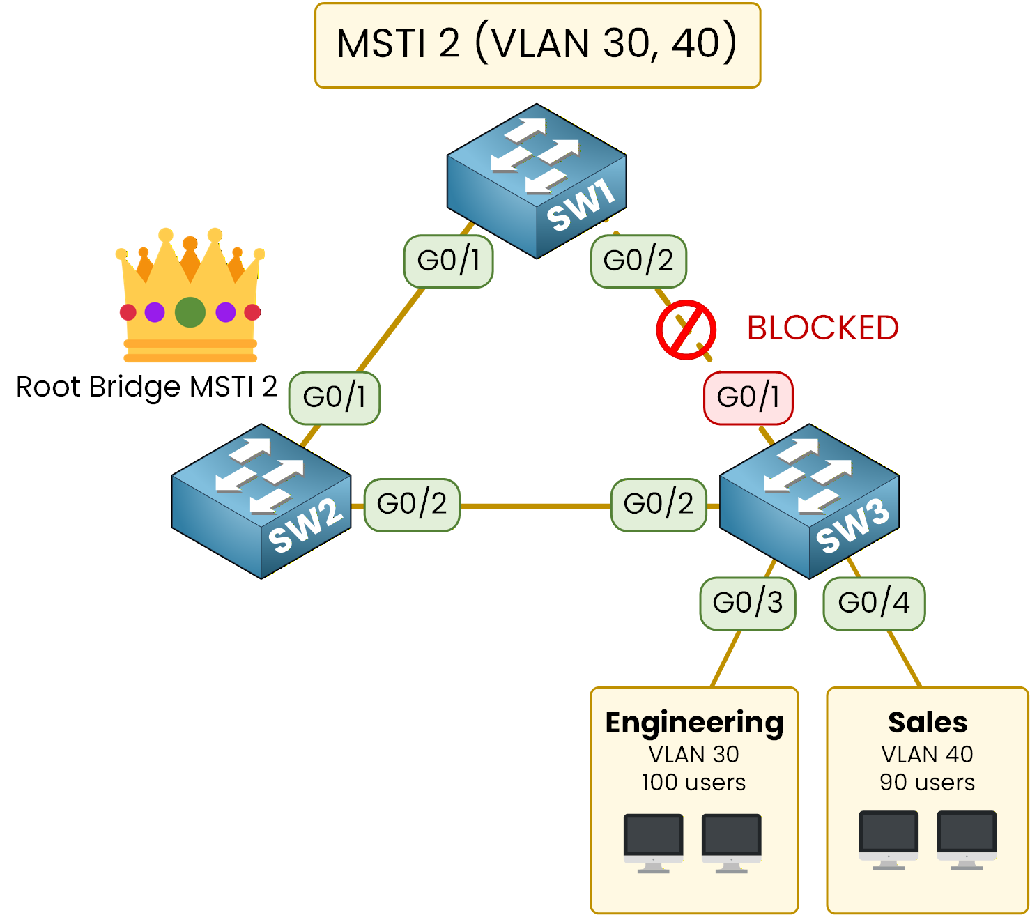
Figure 6 – MSTI 2: VLANs 30-40
An Engineering user sending a packet rides the amber path from SW3, toward SW2.
This time the trunk between SW1 and SW3 is the one that gets blocked, for MSTI 2 only.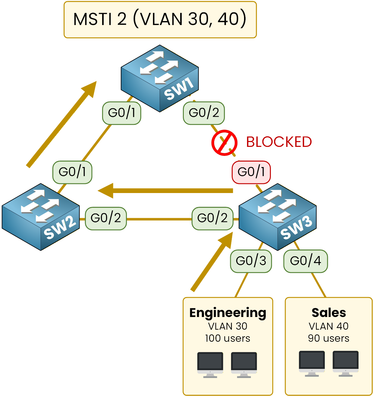
Figure 7 – MSTI 2: Forwarding toward SW2
Same cables, same switches, but two different paths.
The link blocked in MSTI 1 is the link forwarding in MSTI 2, and the other way around.Every Uplink Forwards
Put the two instances on top of each other and look at your three uplinks again.
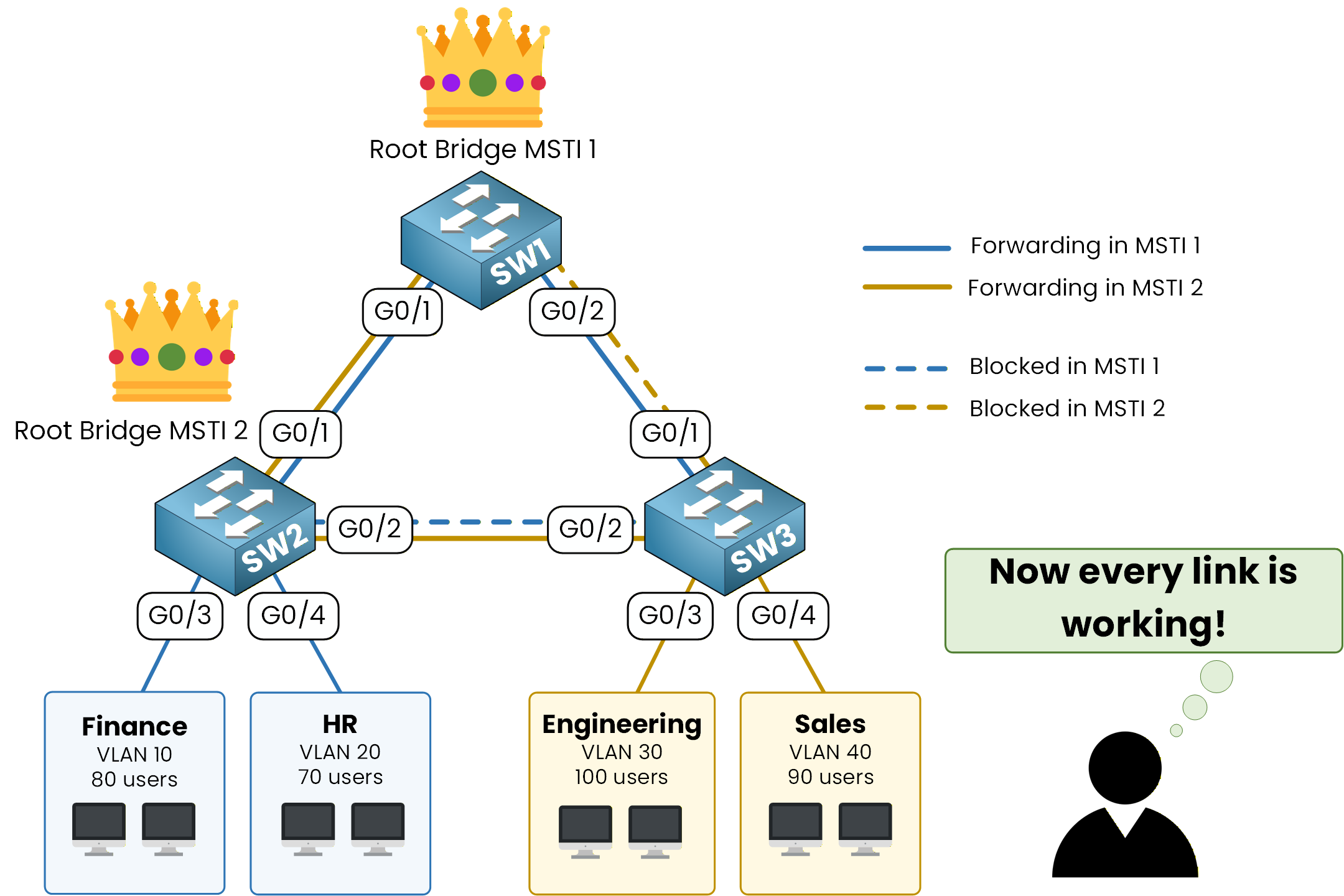
Figure 8 – Balanced paths, zero waste
Every physical uplink now forwards traffic for at least one instance.
The third 1 Gbps link the company paid for finally carries packets.
Two instances, two roots, three active links. That is the whole point of MST.Answer the question below
In this design, which switch is the root for MST instance 2?
Two instances only work if all three switches agree on what those instances are.
MST solves that with the notion of a region.Three Values That Must Match
An MST region is a group of switches that share the same view of the instances.
To belong to the same region, three values must be identical on every switch:Region name, a label of your choice, case-sensitive
Revision number, an integer you bump when the mapping changes
VLAN-to-instance mapping, which VLANs belong to which instance
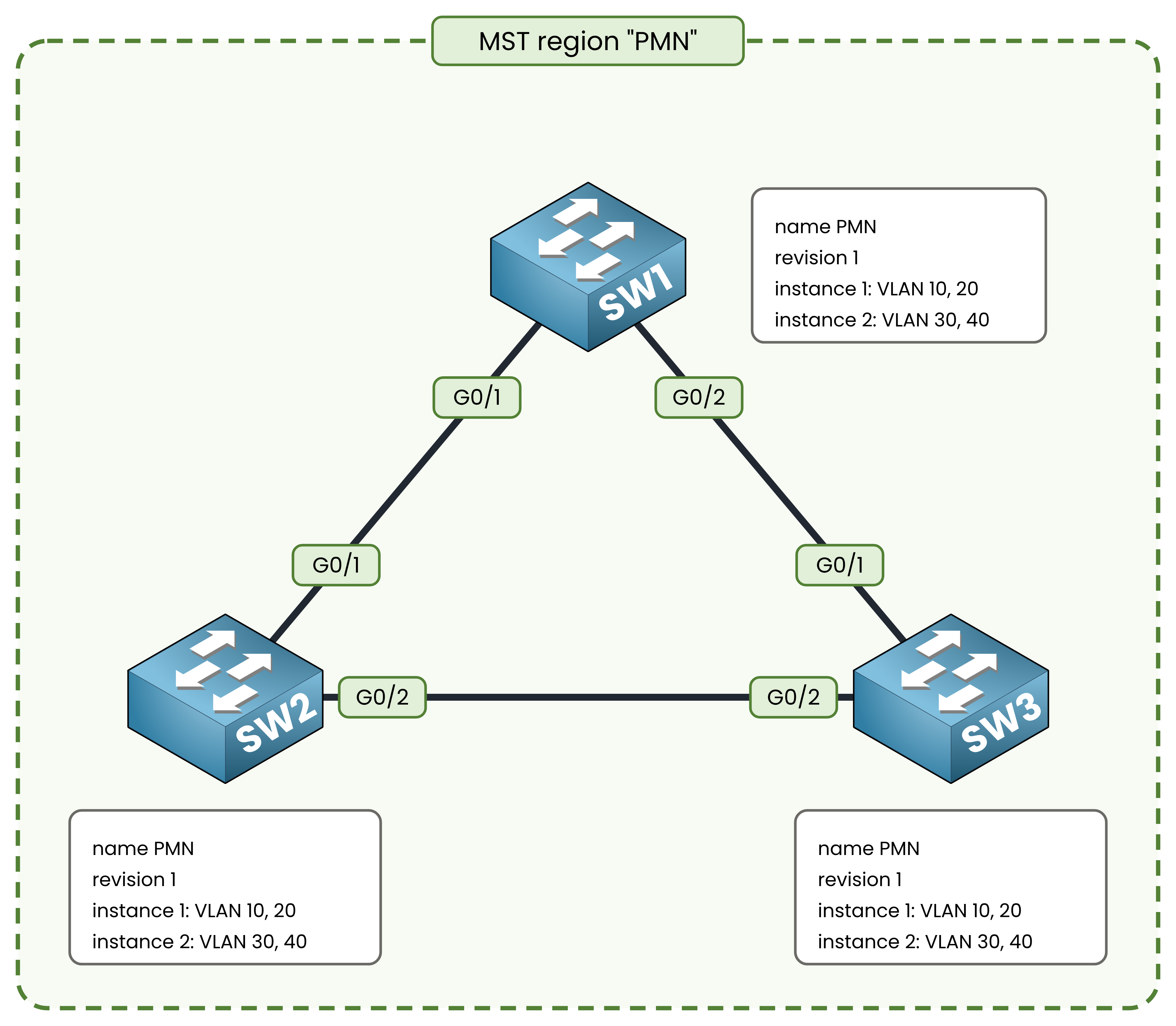
Figure 9 – One region, three identical configurations
Your switches do not send the full mapping in their BPDUs. They send a digest of it, a hash computed from the mapping table.
When a neighbor receives a BPDU with the same name, the same revision and the same digest, it treats the sender as part of its region.
The three values must match exactly, down to the letter case of the name.When Two Switches Disagree
What happens if a colleague sets revision 2 on SW3 and forgets the two other switches?
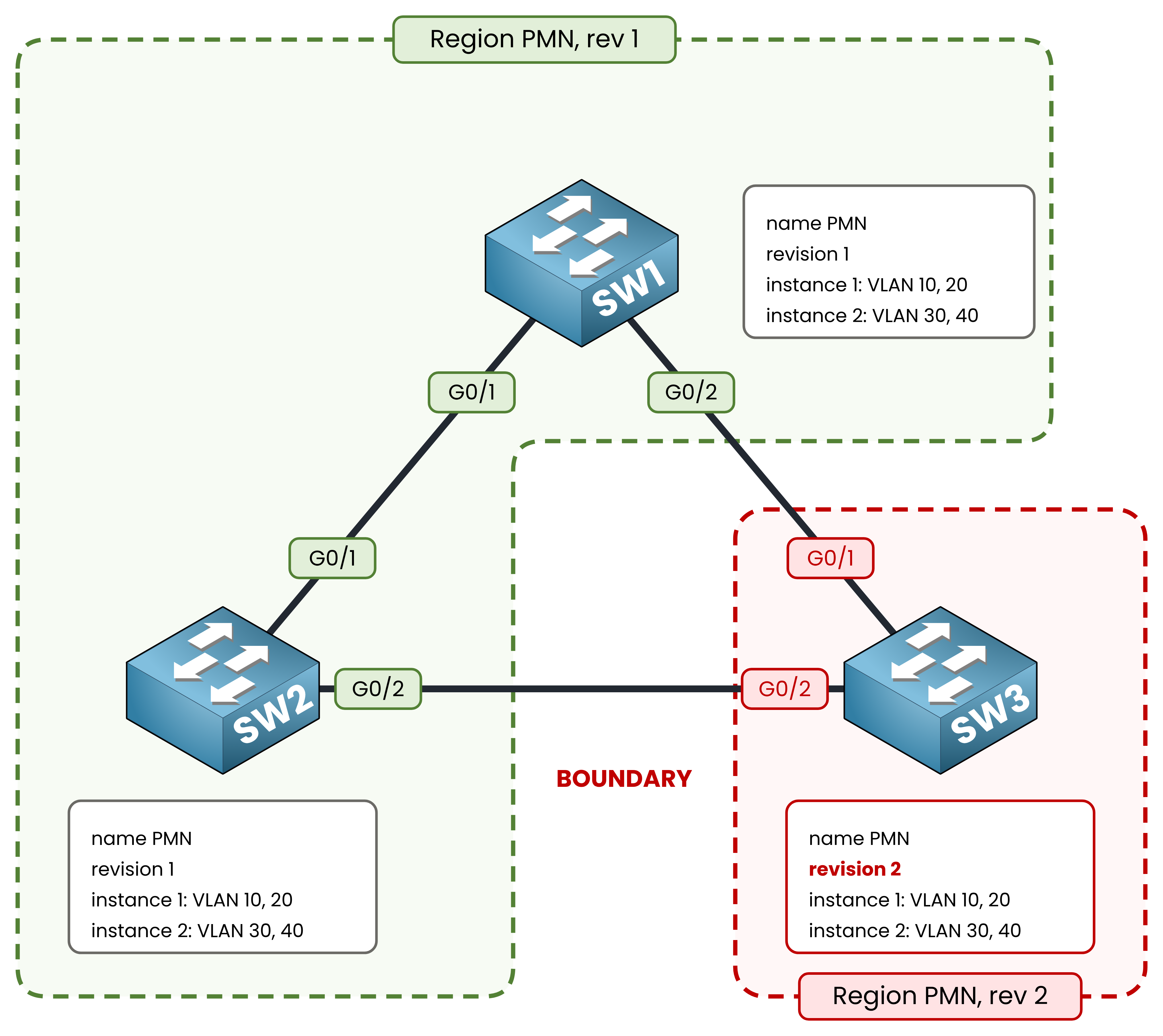
Figure 10 – A revision mismatch splits the region
SW3 now sits in a separate region, alone.
Its two trunks toward SW1 and SW2 become boundary ports, the ports where one region meets another.
Across a boundary, MSTI 1 and MSTI 2 do not exist anymore. The two regions only agree on a single tree, and SW3 sees the whole PMN region as one big switch.
Your per-instance load-balancing on SW3 is gone, and one of its two uplinks goes back to blocking for every VLAN.Nothing is down, no alarm fires. The network simply behaves like the PVST+ picture of Figure 3 again.
That silence is why the region check is the first thing you verify when MST does not do what you expect.Answer the question below
Which of the three region values is an integer you bump when the mapping changes?
Answer the question below
All run CORE rev 5 except SWC (Core); SWD moved VLAN 30, SWB typed in another order: how many regions?
You planned two instances. Your switches will run three.
One concept to know before you configure anything.The Instance You Never Configured
Instance 0 always exists, even if you never type it.
It is called the Internal Spanning Tree (IST), and it is the tree that runs inside your region for everything you left unmapped.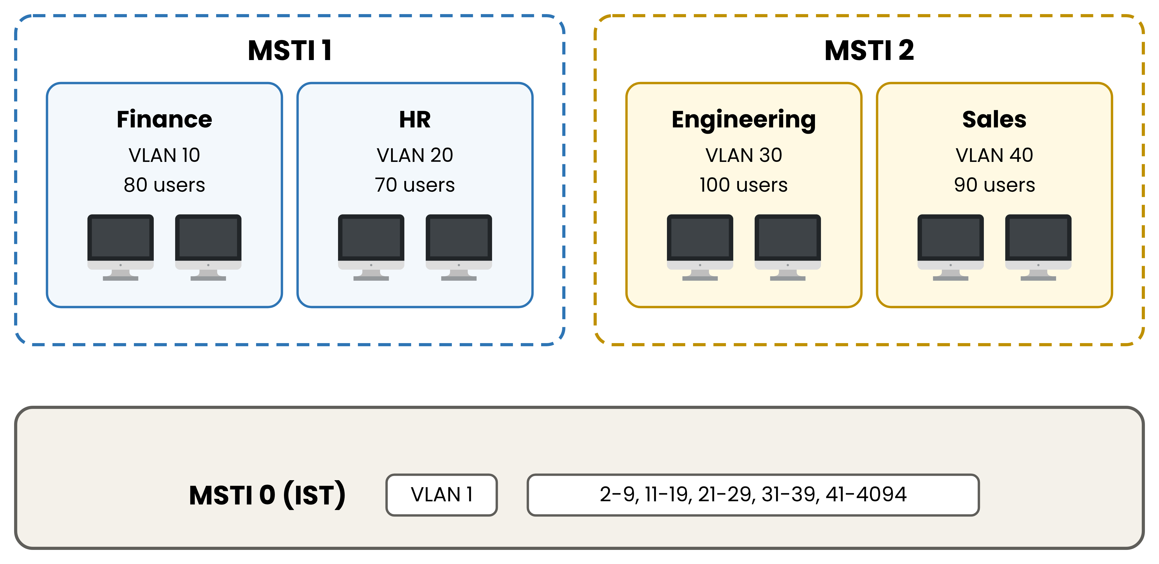
Figure 11 – Instance 0 catches every unmapped VLAN
Instance 0 catches every VLAN you did not explicitly map to a custom instance.
In your network, that means VLAN 1 and the 4089 other VLANs you never created still have a spanning tree, and it is this one.
The IST also does the talking. Its BPDUs carry the region name, revision and digest, and the information of all the other instances rides inside them.It Elects Its Own Root
Like any spanning tree, instance 0 elects a root bridge.
It uses the rule you already know: lowest priority first, then lowest MAC address.
You will choose a root for MSTI 1 and a root for MSTI 2. If you choose nothing for instance 0, the switches choose for you, and the winner is whichever one has the lowest MAC address.Remember that detail. It comes back in the configuration lesson, in a show output you will not expect.
What You Will Build
You now have every piece: two instances, one region with three matching values, and a third instance you did not ask for.
In the next lesson you take the three switches out of PVST+, put them in the same region, and give each instance its own root.
By the end, every uplink of Figure 8 forwards user traffic, on real Cisco IOS output.Answer the question below
Which MST instance holds every VLAN you did not map?