In the previous lessons, you learned about network models and explored the OSI Model.
The OSI Model helped you understand how communication works step by step, layer by layer. It gives you a clear mental framework to analyze network behavior.However, the OSI Model is primarily a theoretical reference.
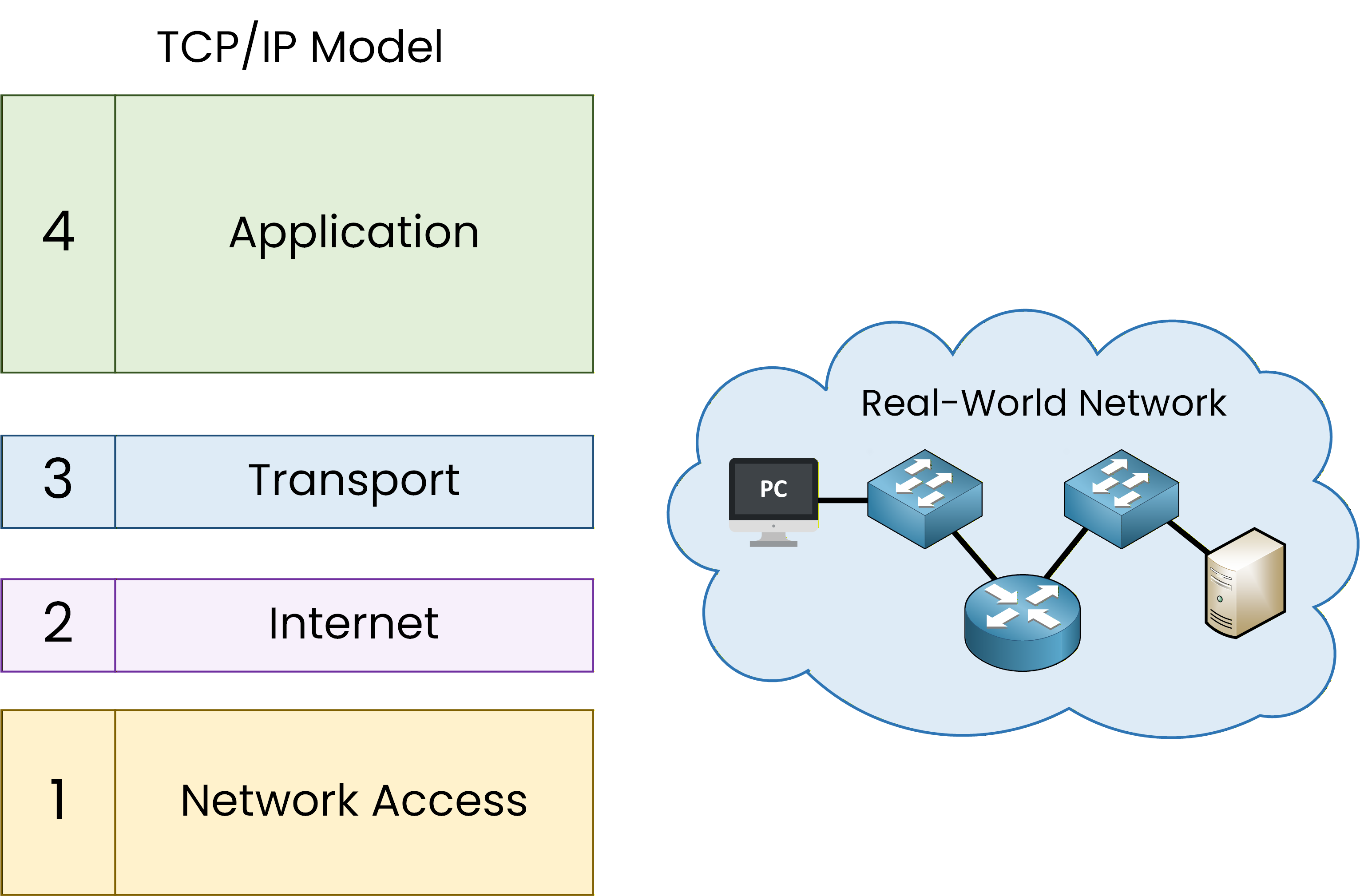
Figure 1 – TCP/IP model and its relationship to real network devices
In real networks, devices do not “run OSI”.
They run protocols and those protocols are organized using the TCP/IP model.The TCP/IP model is not just a concept.
It is actually implemented inside real equipment:your computer,
your router,
your switch,
and every server on the Internet.
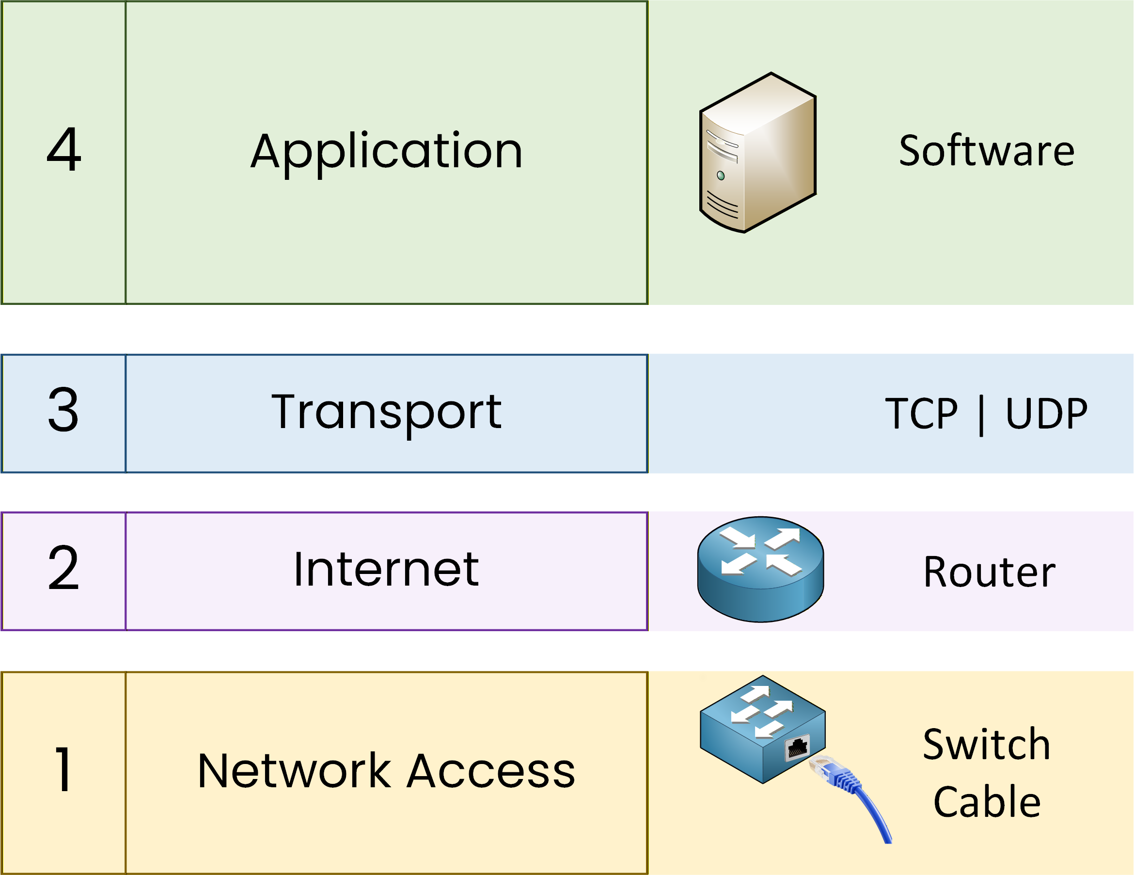
Figure 2 – TCP/IP model and the role of each layer in the real network
This lesson marks an important transition:
from how networking is explained
to how networking actually works
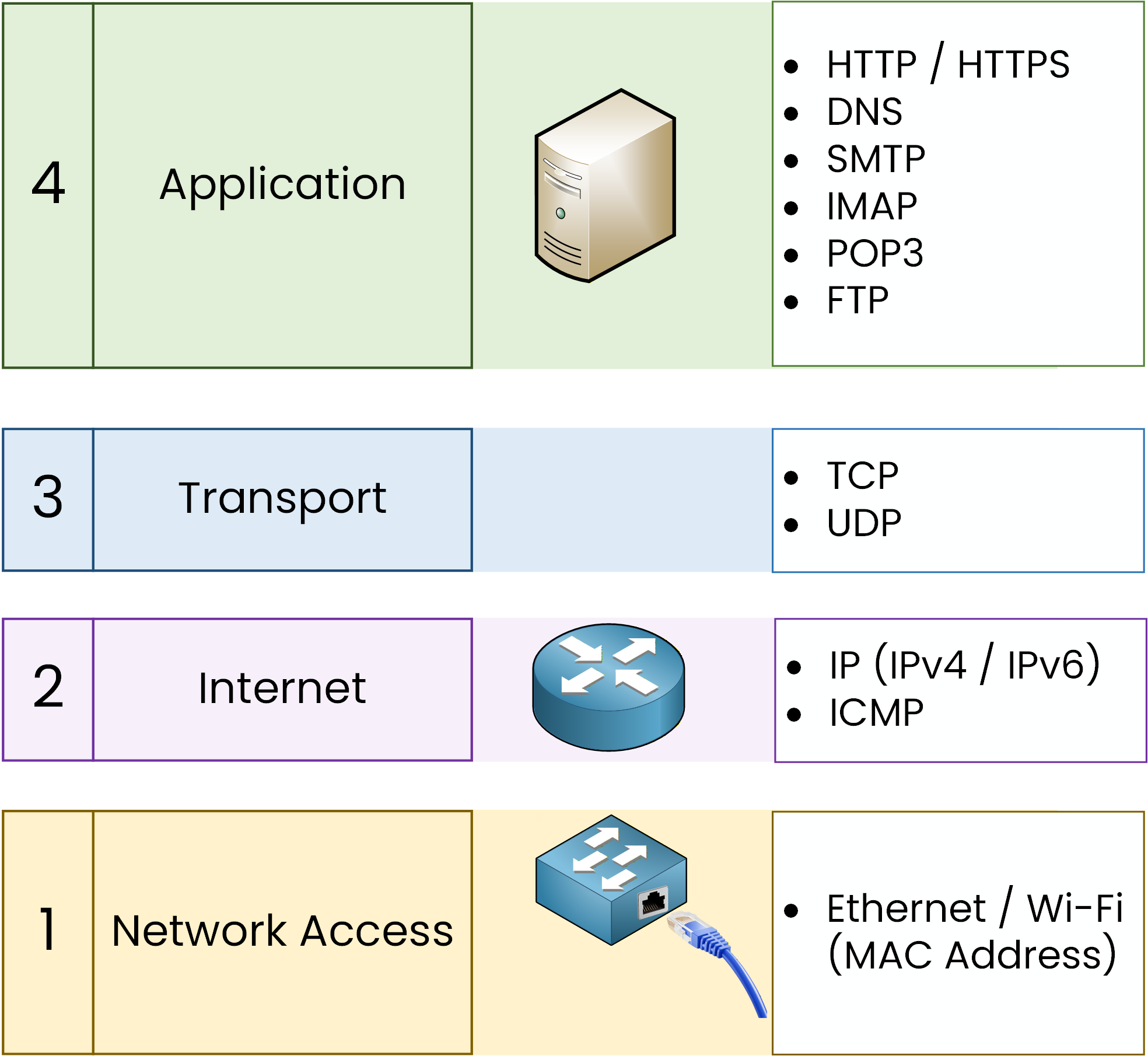
Figure 3 – TCP/IP layers with real devices and associated protocols
Answer the question below
Click 'Complete' to continue
Before we explore the TCP/IP layers, let’s look at how protocols are defined and who sets their rules.
Who defines the rules?
The Internet Engineering Task Force (IETF) is a global community that coordinates the development of Internet standards. It does not “write” every protocol itself. Instead, engineers, researchers, and companies from all over the world form working groups.
Figure 4 – IETF (Internet Engineering Task Force) logo
They propose ideas, discuss them, and refine them until there is a consensus. Once a proposal receives acceptance, the team publishes it as an RFC (Request for Comments).
What is an RFC?
An RFC is a document that explains in detail how a protocol should work.
Think of it as a guide that ensures all devices “speak the same language.”Key facts about RFCs:
Each RFC has a unique number and is free to read online.
Some are informational or experimental, while others become official Internet standards.
RFCs ensure protocols like TCP, IP, DNS, and HTTPS behave the same way across all devices and vendors.
Examples of RFCs
RFC 791 – IPv4: Defines Internet Protocol version 4.
RFC 793 – TCP: Explains how TCP provides reliable communication.
RFC 1149 – IP over Avian Carriers: A humorous RFC describing data transfer using pigeons.🐦
Thanks to RFCs, your laptop, phone, and routers from different brands can all communicate smoothly.
Now that you know how experts standardize protocols, let’s explore the four layers of the TCP/IP Model in detail.Answer the question below
An RFC describes the rules and behavior of a what?
Now that you understand how RFCs standardize protocols, let’s see how they fit into the TCP/IP Model.
From proprietary models to TCP/IP
The TCP/IP Model, also called the Internet Protocol Suite, is the real backbone of modern networking.
It was developed by the U.S. Department of Defense (DoD) in the 1970s and became widely adopted in 1983.Unlike the OSI Model, which is mainly theoretical, the TCP/IP Model is practical and implemented. It defines the protocols your devices use every day to communicate.
The Four Layers of TCP/IP
The TCP/IP Model groups communication into four main layers:
Application
Transport
Internet
Network Access
TCP/IP vs OSI
The diagram below shows how the TCP/IP layers map to the OSI Model, with examples of protocols at each level.
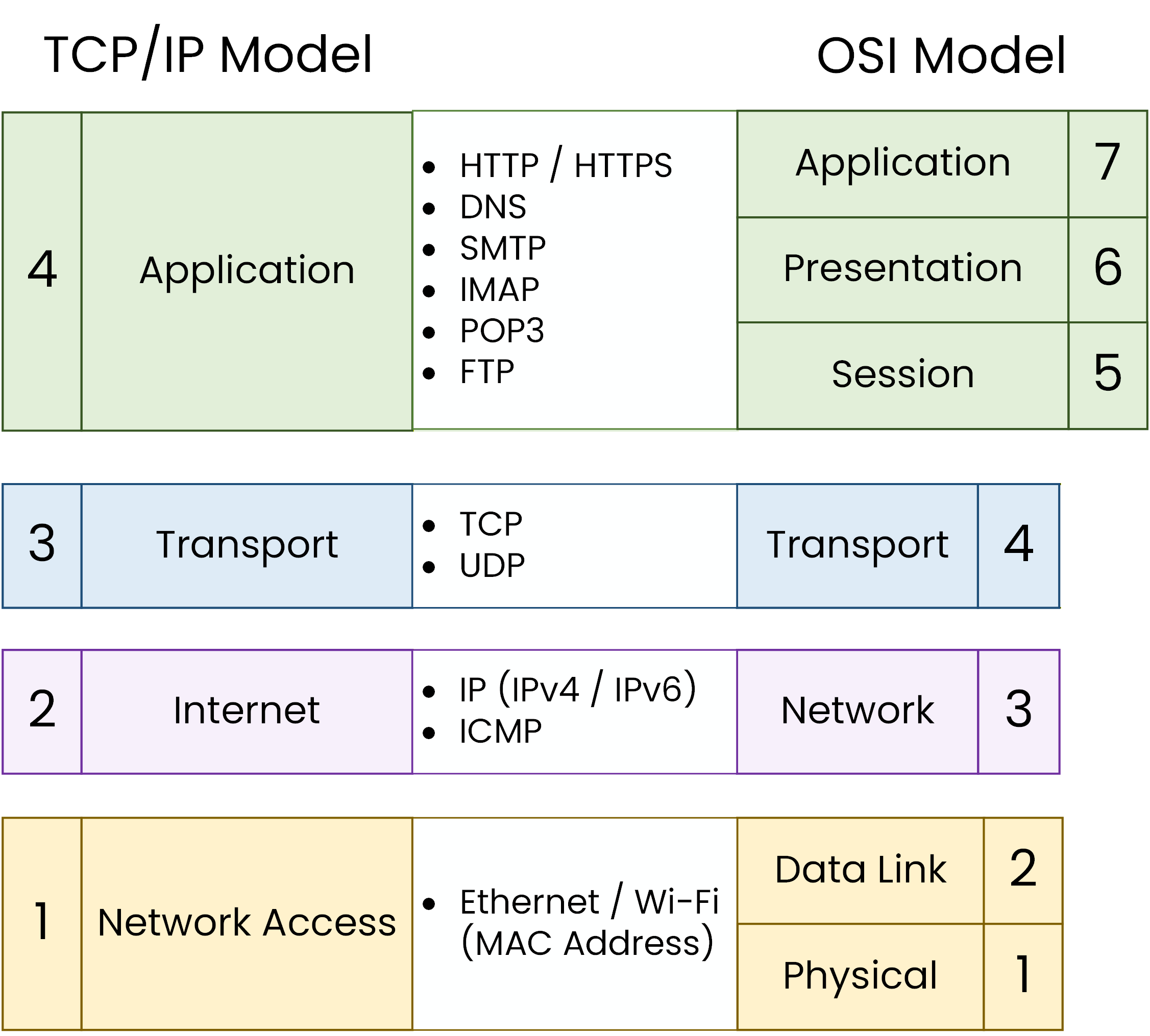
Figure 5 – TCP/IP correspondence → OSI
Keep in mind: OSI is a reference model, while TCP/IP is the real implementation that makes networks work.
Application Layer
The Application Layer combines OSI’s Application, Presentation, and Session layers.
Users interact with the network through services. These include web browsing, sending emails, and transferring files.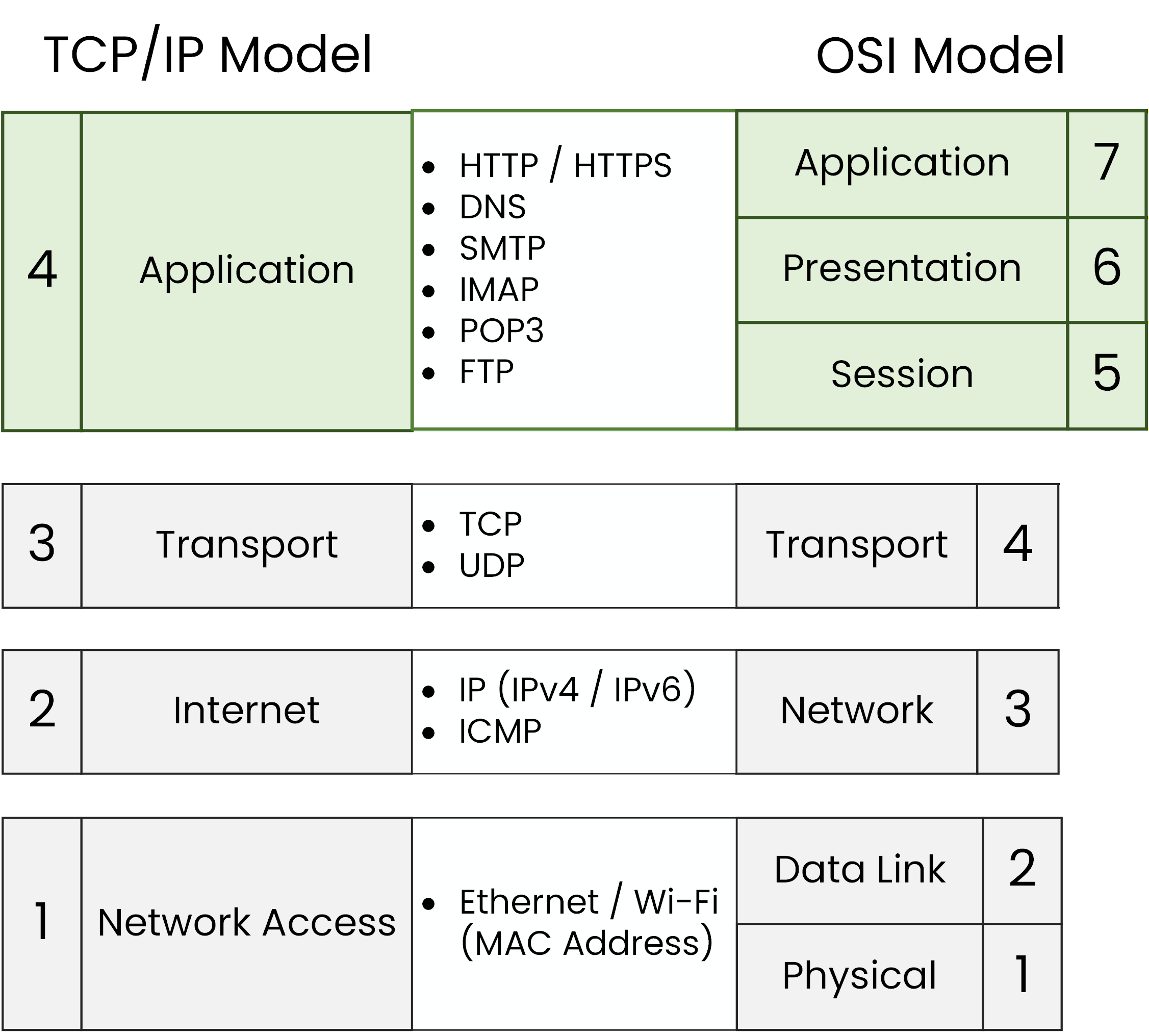
Figure 6 – TCP/IP Application Layer
Examples of protocols:
HTTP/HTTPS → Web Browsing
SMTP/IMAP/POP3 → Email
DNS → Domain Name Resolution
FTP → File Transfers
Some of these may be new to you; that’s fine, you only need to recognize them by name for now.
Transport Layer
The Transport Layer (equal to OSI Layer 4) provides end-to-end delivery between hosts.
It divides data into segments, manages connections, and reassembles streams at the destination.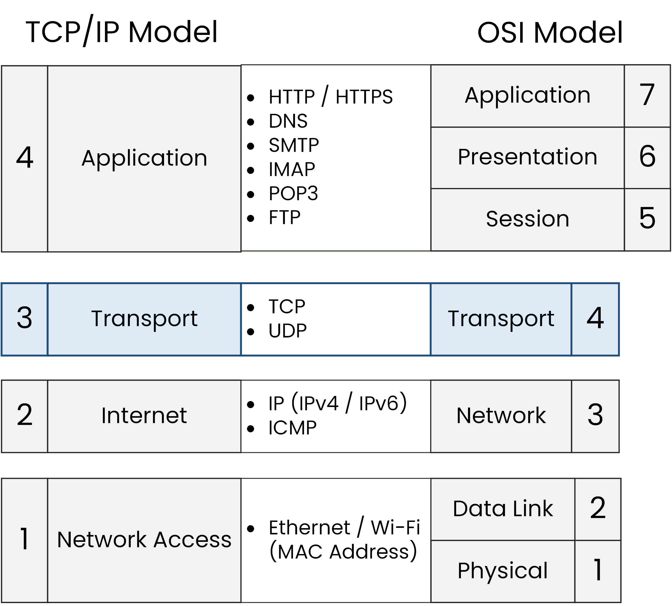
Figure 7 – TCP/IP Transport Layer
Key protocols:
TCP: reliable, connection-oriented
UDP: faster, connectionless, and used in real-time apps
The Transport Layer also uses port numbers to identify services. For example, HTTPS runs on port 443, so when you visit https://pingmynetwork.com, your browser and the server know how to communicate securely.
Let's see this port number for real.
On the PC, check the active connections:C:\> netstat -n Active Connections Proto Local Address Foreign Address State TCP 192.168.1.10:52344 104.21.5.13:443 ESTABLISHEDThe :443 at the end of the foreign address is exactly the port number you just read about, the PC's side of the connection uses a random port (52344 here), while the server always answers on port 443 for HTTPS.
Internet Layer
The Internet Layer (like OSI Layer 3) ensures data can travel across different networks.
Routers operate here, forwarding packets based on IP addresses.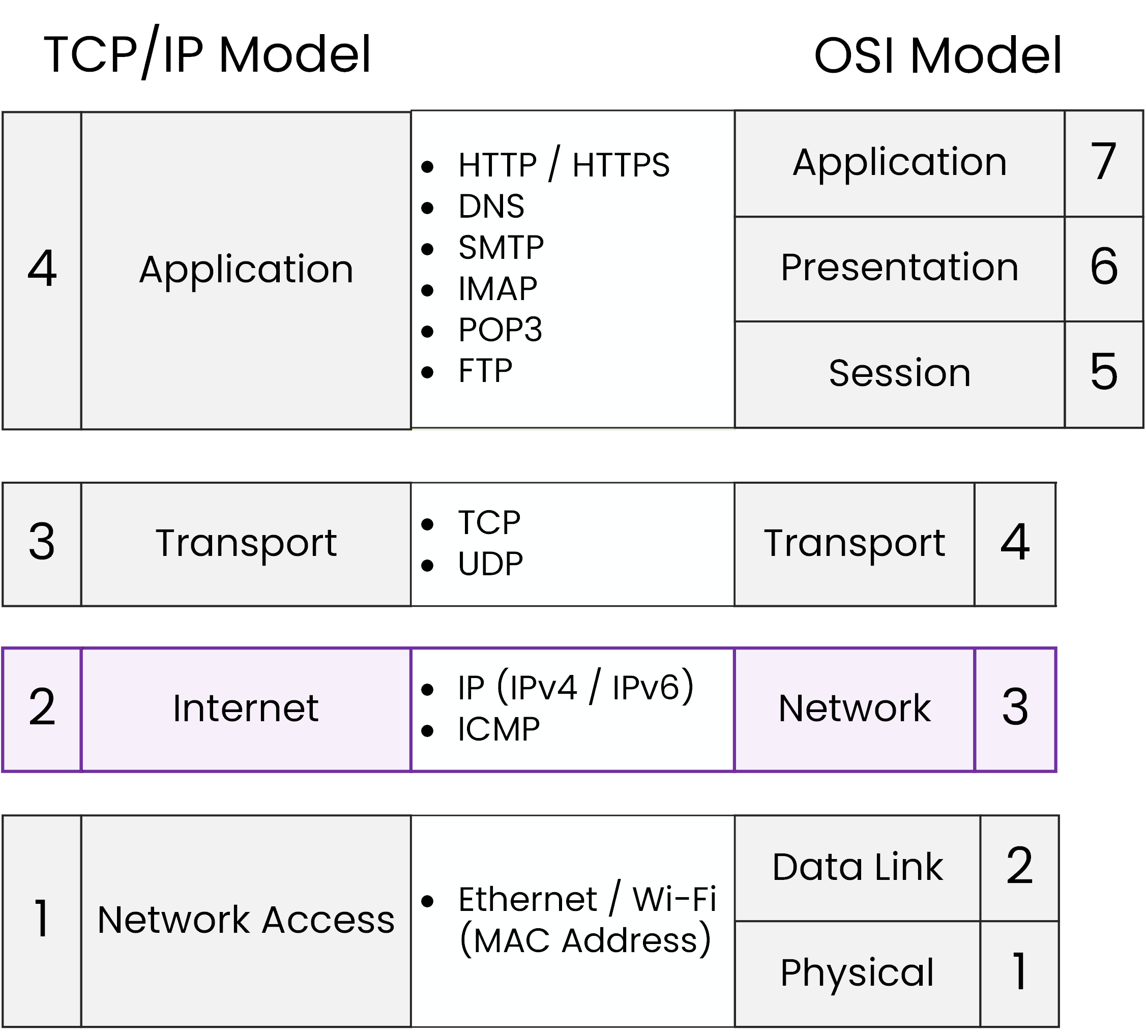
Figure 8 – TCP/IP Internet Layer
Main functions:
IP addressing (IPv4/IPv6) to identify hosts
Routing packets through routers
Diagnostics with ICMP (ping, traceroute)
Address resolution with ARP (IP → MAC)
If ICMP sounds new, don’t worry: it is the protocol behind ping and traceroute.
The Internet Layer’s job is simple but vital: it makes sure your data takes the right path across networks.
Network Access Layer
The Network Access Layer merges OSI’s Data Link and Physical layers.
This is where data actually leaves your device and travels across the network.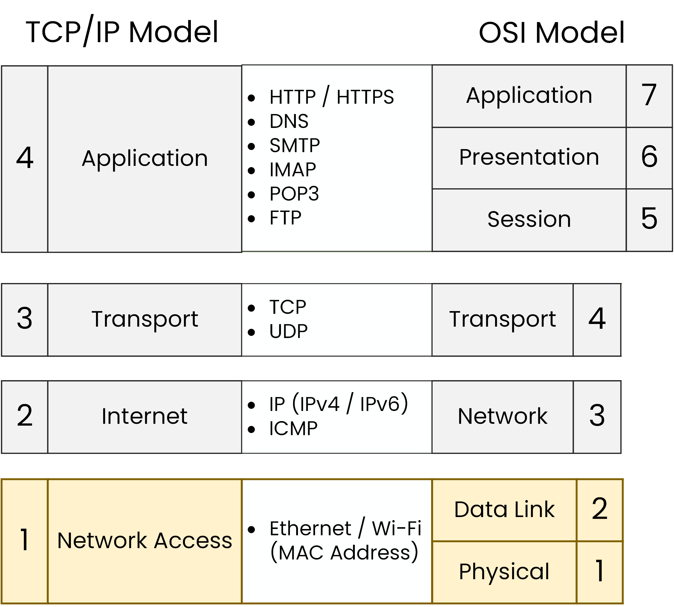
Figure 9 – TCP/IP Network Access Layer
Responsibilities:
Framing with MAC addresses and error checking (FCS)
Media access control (Ethernet CSMA/CD, Wi-Fi CSMA/CA)
Bit transmission as electrical signals (in cables) or as radio waves (in wireless)
Consider this: whether you connect your laptop with a cable or via Wi-Fi, this layer ensures your data moves from one device to another.
Answer the question below
How many layers does the TCP/IP Model have?
To better understand how the TCP/IP layers work together, let’s follow the path of data through a simple network:
Step 1 – From the PC to SW1
The PC sends a message.
When this message arrives at Switch (SW1), the switch does not look at IP addresses.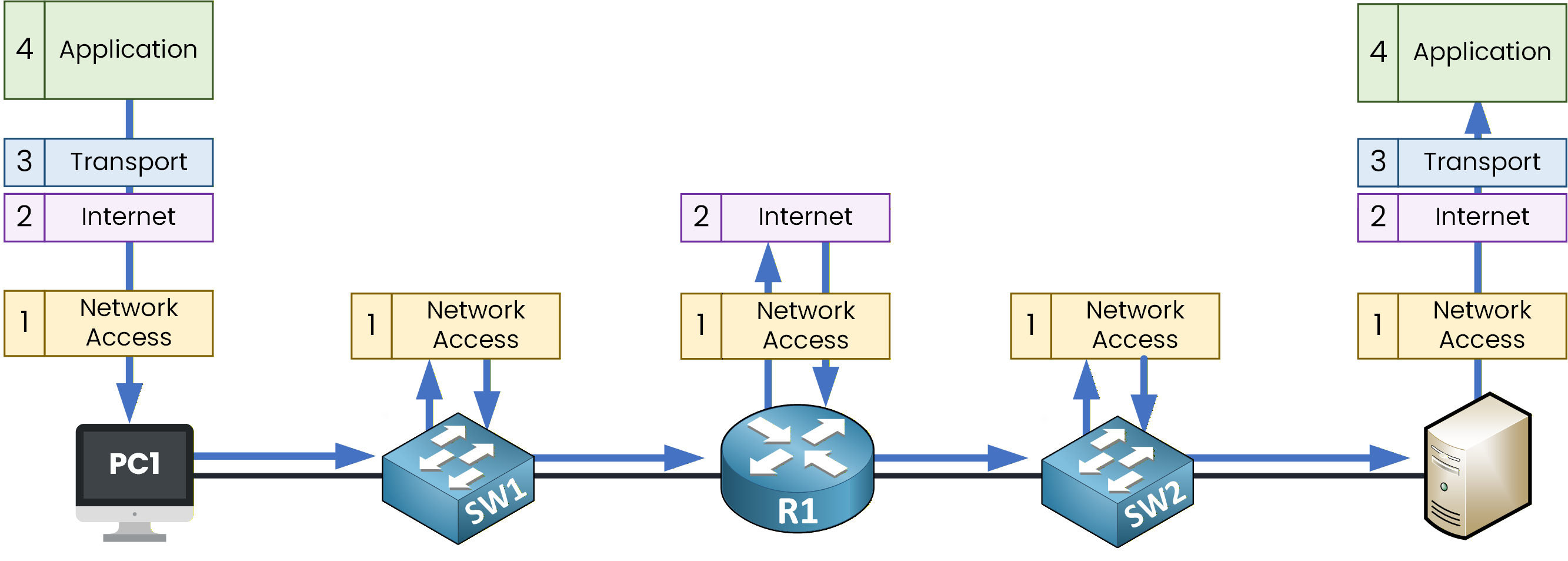
Figure 10 – TCP/IP Data Flow
Let's generate that message ourselves.
From PC1 ping the server:C:\> ping 192.168.2.10 Pinging 192.168.2.10 with 32 bytes of data: Reply from 192.168.2.10: bytes=32 time<1ms TTL=128 Reply from 192.168.2.10: bytes=32 time<1ms TTL=128 Reply from 192.168.2.10: bytes=32 time<1ms TTL=128 Reply from 192.168.2.10: bytes=32 time<1ms TTL=128That ping is the message.
When it reaches Switch (SW1), the switch does not look at IP addresses. Instead, it looks at the physical address (MAC address) inside the frame to decide which port to forward the data to.
At this point, the switch is operating at the Network Access layer of the TCP/IP model.CLI Preview – Switch Perspective (MAC Addresses)
To show this, let’s briefly look inside the switch.
Open the CLI on SW1 and display the MAC address table:SW1> enable SW1# show mac address-table Mac Address Table ------------------------------------------- Vlan Mac Address Type Ports ---- ----------- -------- ----- 1 0001.63dd.b202 DYNAMIC Fa0/2 1 0004.9a75.e9ae DYNAMIC Fa0/1
You do not need to understand every line of this output yet.
For now, just remember this key idea:A switch learns MAC addresses
It uses those MAC addresses to make forwarding decisions
Switches only care about local delivery inside the same network
Step 2 – From SW1 to R1
When the message reaches Router (R1), the behavior changes.
Routers do not forward traffic based on MAC addresses.
Instead, they look at the IP address to decide how to reach the destination network.This is where the Internet layer of the TCP/IP model comes into play.
CLI Preview – Router Perspective (IP Interfaces)
Let’s now look at the router in the middle of the network.
Open the CLI on router R1 and display its IP interfaces:R1> enable R1# show ip interface brief Interface IP-Address OK? Method Status Protocol GigabitEthernet0/0 unassigned YES unset administratively down down GigabitEthernet0/1 192.168.1.1 YES manual up up GigabitEthernet0/2 192.168.2.1 YES manual up up Vlan1 unassigned YES unset administratively down down
Again, you don’t need to fully understand this output yet.
What matters for now is:The router has IP addresses assigned to its interfaces
These IP addresses allow the router to forward traffic between different networks
Routers are what make communication possible beyond the local network.
Step 3 – From R1 to SW2 and the Server
Once the routing decision is made, Router R1 forwards the data toward Switch 2 (SW2).
The router has already used the IP address to choose the correct path.When the data reaches SW2, the switch does not look at IP addresses.
It uses the MAC address to deliver the frame to the correct server on the local network.Finally, the server receives the frame and the data moves up the TCP/IP stack until it reaches the application (for example, a web server sending back a response).
Answer the question below
In the TCP/IP model, IP addressing is handled at which layer — Internet or Transport?
The TCP/IP Model is not theory; it’s the real foundation of the Internet.
Every time you browse a website, send a message, or stream a video, these four layers are at work.Key takeaways from this course
Protocols are standardized through RFCs, ensuring that devices from different vendors can communicate.
TCP/IP has four layers:
Application → user interaction (web, email, DNS)
Transport → reliable or fast delivery using port numbers (TCP/UDP)
Internet → logical addressing and routing with IP addresses
Network Access → local delivery using MAC addresses and physical signals
By now, you understand how data travels from your computer to any server across the Internet.
Answer the question below
Click 'Complete' to continue