VRF (Virtual Routing and Forwarding) is a network virtualization technology that allows a router to have multiple independent routing tables.
Just like VLANs isolate traffic at Layer 2 by creating virtual switches, VRFs isolate routing domains at Layer 3 by creating virtual routers on a single physical device.
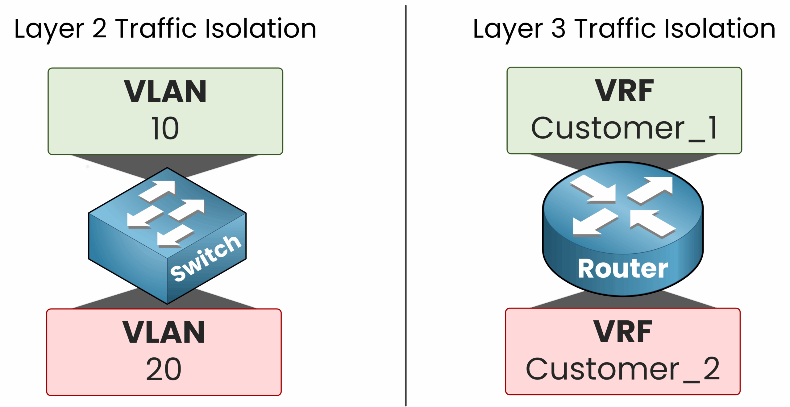
Figure 1 – VLANs isolate Layer 2 traffic and VRFs isolate Layer 3 routing
In this lesson, we'll focus on VRF-Lite, a simplified version of VRF that does not use MP-BGP (Multiprotocol BGP) or MPLS (Multiprotocol Label Switching). This is the type of VRF you need to understand for the CCNA exam. To help you grasp its value, let's walk through a real-world example.
Answer the question below
What does a VRF isolate at Layer 3?
Imagine a Service Provider needs to connect two customers to the same ISP router.
As the diagram shows, both Customer 1 and Customer 2 need to access the internet through the ISP. But the network engineer is facing a key question: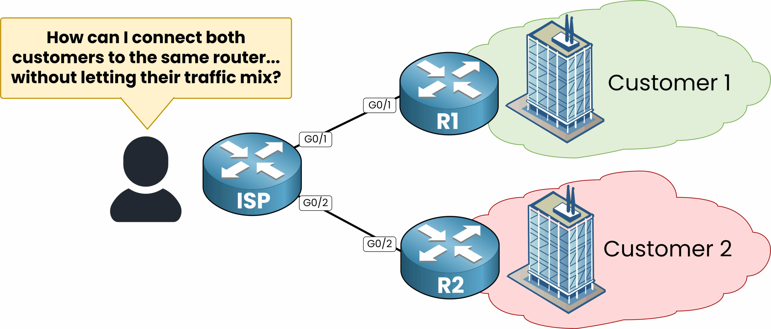
Figure 2 – Connecting two customers to the same ISP router without isolating their traffic
By default, the ISP router uses a single global routing table.
As soon as both customers are connected, the ISP router learns their networks and inserts them into its routing table.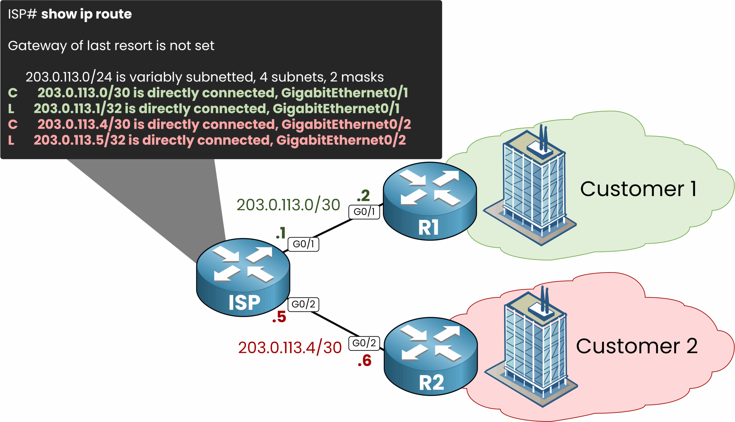
Figure 3 – Without VRF: all routes in one routing table.
This leads to a serious risk of traffic leakage between customers, since the ISP router doesn't distinguish between Customer 1 and Customer 2's routes.
This means Customer 1 could potentially reach Customer 2's network if we're not careful, which is a serious security risk.What we need is a way to completely separate Customer 1's routes from Customer 2's routes. This is exactly what Virtual Routing and Forwarding (VRF) allows us to achieve.
Answer the question below
What problem occurs when an ISP router uses a single global routing table for multiple customers?
With VRF, we can turn a single physical router into multiple virtual routers. In our example, we'll create two virtual routing instances:
One VRF named
Customer_1with its own routing tableOne VRF named
Customer_2with its own routing table
Then, we assign the appropriate physical interfaces to each VRF.
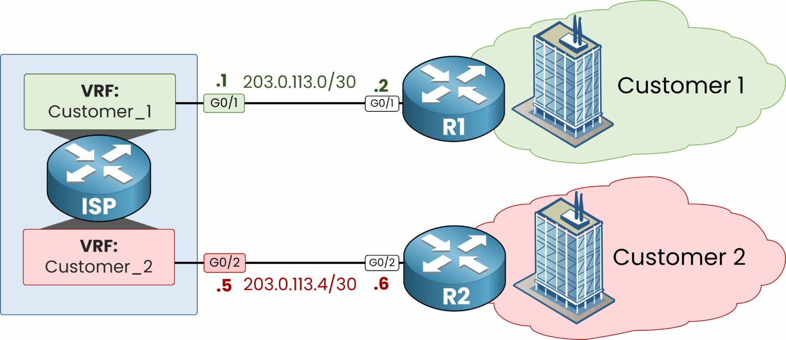
Figure 4 – VRFs create separate routing instances per customer.
At this point, the ISP router hosts two independent routing environments:
Each VRF has its own set of interfaces
Each VRF has its own routing table
And there is complete separation between the two
Each customer is now isolated within its own VRF: Customer 1 and Customer 2 cannot see or reach each other, even though they share the same physical ISP router.
Answer the question below
What does each VRF have to keep customer traffic separated?
VRF brings two key benefits for your CCNA study.
Independent Routing Tables
Each VRF maintains its own routing table that is completely separated from others.
By default:
Traffic from one VRF can't reach another
Routing entries and interfaces are fully isolated
We can look at the content of our two VRFs with the show ip route vrf vrf-name command:
Figure 5 – Each VRF has its own routing table.
Start with the first VRF on the ISP router:
ISP# show ip route vrf Customer_1
Routing Table: Customer_1

      203.0.113.0/24 is variably subnetted, 2 subnets, 2 masks
C        203.0.113.0/30 is directly connected, GigabitEthernet0/1
L        203.0.113.1/32 is directly connected, GigabitEthernet0/1
The table of
Customer_1holds a single connected network,203.0.113.0/30on Gi0/1.
Nothing from Customer 2 shows up here, even though both customers sit on the same router.Now run the same command against the second VRF:
ISP# show ip route vrf Customer_2
Routing Table: Customer_2

      203.0.113.0/24 is variably subnetted, 2 subnets, 2 masks
C        203.0.113.4/30 is directly connected, GigabitEthernet0/2
L        203.0.113.5/32 is directly connected, GigabitEthernet0/2
Same command, completely different answer.
Customer_2only sees203.0.113.4/30on Gi0/2.
Two tables, two isolated worlds, one physical router.That isolation unlocks a second benefit: the ability to reuse overlapping IP addresses without conflict.
Overlapping IP Addresses
For example:
Customer_1uses the subnet203.0.113.0/30inside its VRFCustomer_2also uses203.0.113.0/30in its own VRF
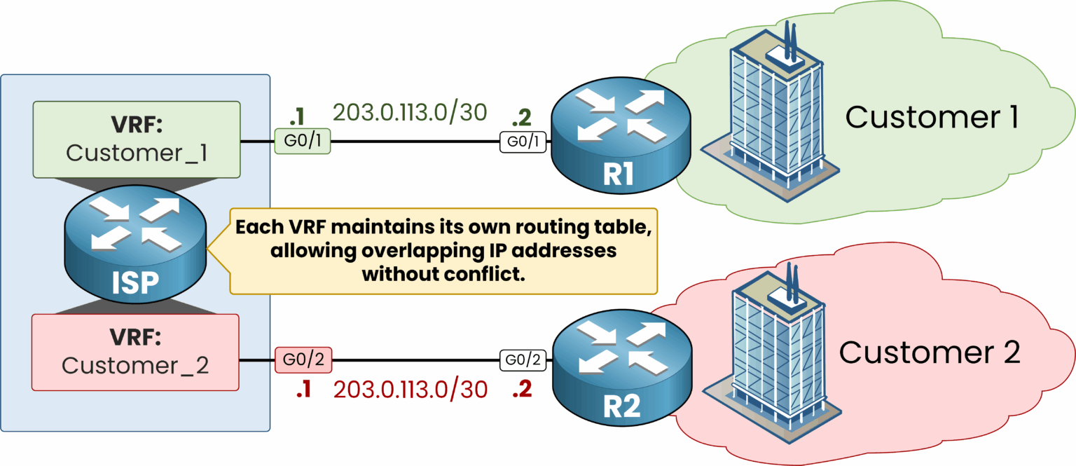
Figure 6 – VRFs allow overlapping IPs without conflict.
But how is that possible?
Because each VRF creates a completely isolated routing environment.
This means:
Each VRF has its own routing table
Each VRF has its own interfaces
The router treats the same IP address differently depending on the VRF
So, even if both customers use the same IP subnet, the router knows which one to use because the traffic is bound to a specific VRF via the interface.
Answer the question below
What VRF benefit allows customers to use the same subnet without conflict?
After understanding the concept of overlapping IPs, let's see how this works in a real configuration.
In the previous diagram (Figure 6), we saw two customers sharing the same subnet without conflict. Figure 7 expands that topology:
Remote customer routers R3 and R4 are added
The ISP router is prepared with two separate VRFs
This is the topology used for the configuration that follows.
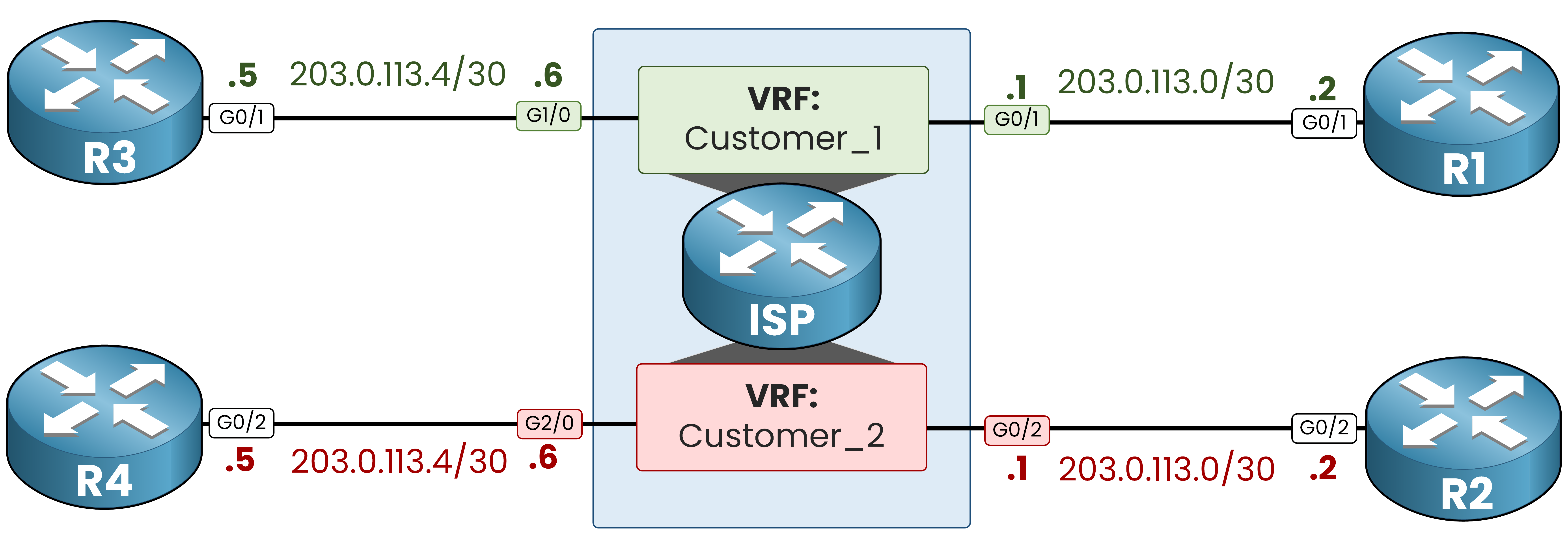
Figure 7 – VRF configuration on the ISP router with isolated customers
You don't need to configure VRF Lite for the CCNA exam, but seeing it done once in practice is worth it. The configuration is simple.
Since we have two customers, we will create two VRFs.
STEP 1 – Create the VRFs
We begin by creating two virtual routing instances on the ISP router:
ISP# conf t
Enter configuration commands, one per line.  End with CNTL/Z.
ISP(config)# ip vrf Customer_1
ISP(config-vrf)# exit
ISP(config)# ip vrf Customer_2
ISP(config-vrf)# exit
Each VRF acts like a separate logical router inside the same physical device.
STEP 2 – Assign Interfaces to Each VRF
We now assign the correct interfaces to each VRF and configure IP addresses.
Interfaces for Customer_1:
ISP(config)# interface g0/1
ISP(config-if)# ip vrf forwarding Customer_1
ISP(config-if)# ip address 203.0.113.1 255.255.255.252
ISP(config-if)# no shutdown
%LINK-5-CHANGED: Interface GigabitEthernet0/1, changed state to up
%LINEPROTO-5-UPDOWN: Line protocol on Interface GigabitEthernet0/1, changed state to up
ISP(config-if)# exit

ISP(config)# interface g1/0
ISP(config-if)# ip vrf forwarding Customer_1
ISP(config-if)# ip address 203.0.113.6 255.255.255.252
ISP(config-if)# no shutdown
%LINK-5-CHANGED: Interface GigabitEthernet1/0, changed state to up
%LINEPROTO-5-UPDOWN: Line protocol on Interface GigabitEthernet1/0, changed state to up
ISP(config-if)# exit
Interfaces for Customer_2:
ISP(config)# interface g0/2
ISP(config-if)# ip vrf forwarding Customer_2
ISP(config-if)# ip address 203.0.113.1 255.255.255.252
ISP(config-if)# no shutdown
%LINK-5-CHANGED: Interface GigabitEthernet0/2, changed state to up
%LINEPROTO-5-UPDOWN: Line protocol on Interface GigabitEthernet0/2, changed state to up
ISP(config-if)# exit

ISP(config)# interface g2/0
ISP(config-if)# ip vrf forwarding Customer_2
ISP(config-if)# ip address 203.0.113.6 255.255.255.252
ISP(config-if)# no shutdown
%LINK-5-CHANGED: Interface GigabitEthernet2/0, changed state to up
%LINEPROTO-5-UPDOWN: Line protocol on Interface GigabitEthernet2/0, changed state to up
ISP(config-if)# end
⚠️ Note: Always apply the ip vrf forwarding vrf-name command before configuring the IP address. This command removes any IP address already configured on the interface.
STEP 3 – Verify VRF Interface Assignment
The
show ip vrfcommand lists every VRF on the router with the interfaces attached to it:ISP# show ip vrf Name Default RD Interfaces Customer_1 <not set> Gi0/1, Gi1/0 Customer_2 <not set> Gi0/2, Gi2/0Here we can see the interfaces associated with each VRF.
STEP 4 – Check Routing Tables per VRF
Each VRF keeps a separate and isolated routing table.
Check the content of each one withshow ip route vrf vrf-name:Both tables are shown below.
ISP# show ip route vrf Customer_1
Routing Table: Customer_1

 203.0.113.0/24 is variably subnetted, 4 subnets, 2 masks
C    203.0.113.0/30 is directly connected, GigabitEthernet0/1
L    203.0.113.1/32 is directly connected, GigabitEthernet0/1
C    203.0.113.4/30 is directly connected, GigabitEthernet1/0
L    203.0.113.6/32 is directly connected, GigabitEthernet1/0
ISP# show ip route vrf Customer_2 Routing Table: Customer_2 203.0.113.0/24 is variably subnetted, 4 subnets, 2 masks C 203.0.113.0/30 is directly connected, GigabitEthernet0/2 L 203.0.113.1/32 is directly connected, GigabitEthernet0/2 C 203.0.113.4/30 is directly connected, GigabitEthernet2/0 L 203.0.113.6/32 is directly connected, GigabitEthernet2/0As you can see, each VRF has its own routing table, with its own connected networks and interfaces.
Even though the subnets are identical, the router handles them as separate thanks to VRF.Answer the question below
Which command shows the interfaces assigned to each VRF?
VRF Lite is a powerful solution that allows a single physical router to behave like multiple virtual routers. This solves the challenge of route separation when multiple customers connect to the same ISP device.
By default, a router uses a single global routing table, which creates a risk of traffic leakage between customers.
With VRF, each customer operates in a fully isolated routing environment.
Every VRF has its own routing table and its own interfaces.
Overlapping IP addresses are treated as completely separate.
For example, both Customer 1 and Customer 2 can use the subnet
203.0.113.0/30without conflict, because each subnet exists in its own VRF and is processed independently.On the configuration side: create the VRFs, assign the interfaces and IP addresses, then verify with
show ip vrfandshow ip route vrf.VRF Lite offers a simple and scalable way to isolate routing domains on the same device, an important concept to understand for the CCNA exam.
Answer the question below
Click 'Complete' to continue