Classification and Marking

1. What is Classification ?

In networking, QoS classification and marking are the foundation of traffic prioritization. Classification allows you to identify and group different types of traffic while marking assigns values that determine how this traffic should be treated across the network.

Classification is the process of identifying and organizing traffic into distinct classes.

For example, you might decide:

  • "This traffic is critical for our business."

  • "This traffic is not urgent and can wait."

  • "This traffic is unrelated to business operations and should have the lowest priority."

In our example, traffic is divided into four classes:

Diagram showing QoS classification process, where incoming traffic on interface G0/0 is categorized into Real-Time, Business Critical, Best Effort, and Scavenger classes based on priority.

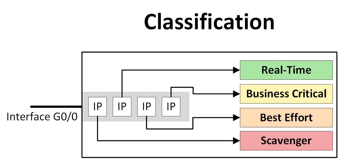
Figure 1 – Traffic Classification

The diagram below demonstrates how traffic entering an interface (G0/0) is classified into these categories based on its priority:

  • Real-Time: Ensures smooth delivery of Voice over IP (VoIP) and video traffic.

  • Business Critical: Prioritizes essential business services like server or application traffic.

  • Best Effort: Handles standard traffic without any special priority, such as web browsing or emails.

  • Scavenger: Low-priority traffic, typically entertainment or non-business-related activities.

By classifying traffic, you enable effective network management, ensuring that critical operations are prioritized and not impacted by less important activities.

Why close to the source? Applying classification and marking near the source ensures that traffic is prioritized correctly as it enters the network. This avoids unnecessary delays or mismanagement of resources further along the packet's journey.

How to Classify Traffic

Traffic classification can be achieved using various methods. Here are the two most common approaches:

Diagram showing IOS traffic classification methods, with two main approaches: ACL (Access Control Lists) and NBAR (Network-Based Application Recognition).

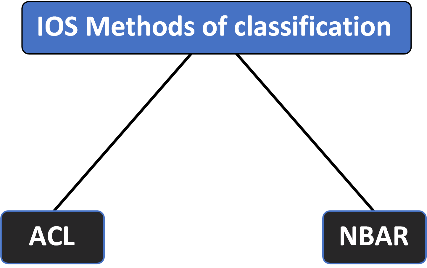
Figure 2 – IOS Methods of Traffic Classification

Using ACLs (Access Control Lists):

  • ACLs define rules to identify specific types of traffic on a network device.

  • For instance, you could create an ACL to classify traffic originating from a subnet hosting critical servers, ensuring that this traffic receives higher priority.

Using NBAR (Network-Based Application Recognition):

  • NBAR employs deep packet inspection to identify traffic by applications, protocols, or services.

  • This method is particularly useful when traffic patterns are complex or involve a variety of applications.

2. What is Marking?

Once traffic has been classified into different classes, the next step is marking.

This involves assigning a specific value to each class, allowing network devices to identify and prioritize traffic efficiently according to the value in the packet header.

Marking Using Values

Below is an example where traffic is assigned specific values. (If you're not familiar with these values yet, don’t worry! We’ll cover them in detail later in the course.)

Diagram showing traffic classification and marking on interface G0/0, where IP packets are assigned values like EF, CS4, DF, and CS1 to prioritize Real-Time, Business Critical, Best Effort, and Scavenger traffic respectively.

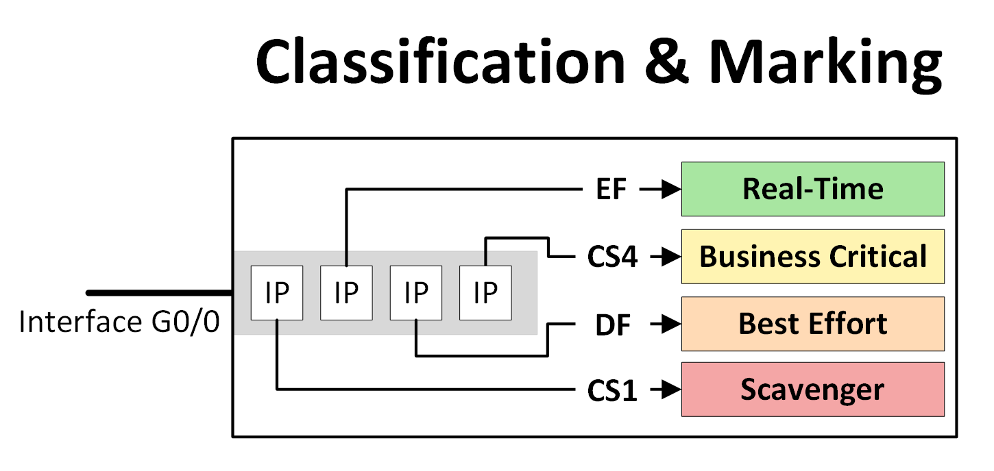
Figure 3 – Classification & Marking

Once a packet is marked, subsequent routers and switches only need to read the marking value to determine the traffic’s priority, without having to reclassify it.

Diagram illustrating QoS classification and marking at SW1 using ACL or NBAR, with subsequent switches and routers reading marking values to prioritize traffic toward the rest of the network.

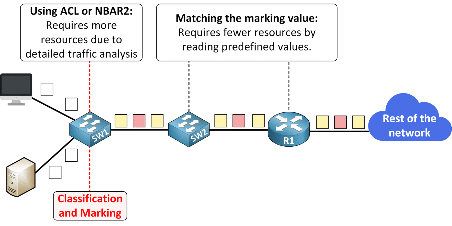
Figure 4 – Marking vs Matching

Methods of Marking Traffic

To implement marking, various methods can be used depending on the layer:

  • Layer 2 Marking (Data Link Layer)

  • Layer 3 Marking (Network Layer)

Let’s start by exploring Layer 2 Marking in detail!

3. Layer 2 Marking

What is PCP?

PCP (Priority Code Point) is a 3-bit field in the 802.1Q tag found in Ethernet frames.

It is used for Layer 2 QoS marking, allowing devices to categorize and prioritize traffic directly at the Ethernet frame level.

Diagram showing the 802.1Q tag structure for Layer 2 QoS marking, highlighting the Priority Code Point (PCP) field used to assign priority values from 0 to 7 within Ethernet frames.

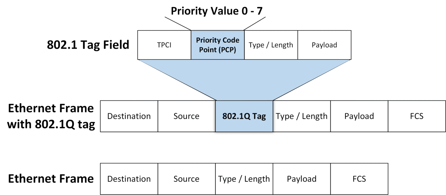
Figure 5 – PCP Field in 802.1Q for Layer 2 Marking

Understanding PCP Values

CoS uses 3 bits, allowing for 8 possible values (0–7). However, Cisco reserves values 6 and 7 for internal use by network control protocols, such as routing updates or OSPF. These values are critical for ensuring that routing protocols receive the highest priority without interference from other traffic.

Table of PCP (Priority Code Point) values used in QoS Layer 2 marking, listing decimal values from 0 to 7 with corresponding traffic types like best effort, voice, video, and network control, ordered from lowest to highest priority.

Figure 6 – PCP Values and Traffic Priority

The recommended CoS value for real-time traffic, such as VoIP is 5 which ensures high priority while avoiding the reserved values.

Since the 802.1Q header is not included in all Ethernet frames, PCP marking only works when 802.1Q trunking is enabled on a link.

PCP in Practice

Let's consider the scenario below: the switch has a trunk port that enables traffic to be sent marked on Layer 2 PCP.

Diagram showing how Layer 2 PCP values are used for QoS classification and marking over trunk links, with traffic marked by switches, categorized by priority class (Real-Time, Business Critical, Best Effort, Scavenger), and the PCP value lost when passing through a router.

Figure 7 – PCP in Practice (Layer 2 QoS Marking and Trunk Links)

For example, traffic between a server on the left and a server behind R2 is classified as business-critical and assigned a PCP value of 3. This marking remains valid only on the trunk link.

However, once the Ethernet frame reaches the first router, the router replaces the Ethernet header, causing the PCP value to be lost.

Limitation of PCP Marking:

  1. Headers are replaced at each hop: Routers replace the source and destination MAC addresses for the next segment of the journey, removing the original Ethernet frame and any PCP markings.

  2. Marking doesn't persist end-to-end: Since Layer 2 information is lost, prioritization does not continue beyond the first router.

To address these challenges, Layer 3 marking (DSCP) is required to ensure prioritization persists across the entire network path.

4. Understanding Layer 3 Marking

Layer 3 marking involves embedding priority information in the IP header, allowing routers to prioritize traffic consistently from the source to the destination.

Unlike Layer 2 marking (PCP), which is tied to Ethernet frames and replaced when the Ethernet frames hit a router, Layer 3 markings persist throughout the packet’s lifecycle, ensuring end-to-end QoS.

How Layer 3 Marking Works

When a host sends data, the IP packet is encapsulated within a data-link frame. As the packet travels through the network:

  1. Routers replace the data-link header at each hop with a new one for the next link.

  2. The IP header remains unchanged, preserving the Layer 3 QoS marking.

Real-World Example: End-to-End Consistency

Imagine a server on the left sending traffic to another server across multiple routers (R1 and R2). At R1, the packet is marked with a Layer 3 DSCP value. This marking persists all the way to the destination, ensuring consistent traffic prioritization.

Diagram illustrating end-to-end QoS consistency using DSCP marking, where traffic is classified and marked at R1 with a DSCP value, and this Layer 3 QoS marking is preserved across the network to ensure consistent prioritization between servers.

Figure 8 – Real-World Example: End-to-End Consistency with DSCP

IPP (Old Use)

In earlier implementations of IPv4, the Type of Service (ToS) byte included a 3-bit IP Precedence (IPP) field for marking traffic priority. This provided 8 possible values (0–7), similar to PCP at Layer 2.

Diagram of the IPv4 header highlighting the old IP Precedence (IPP) field in the Type of Service (ToS) byte, showing how 3 bits were used to prioritize traffic in early RFC 791 implementations.

Figure 9 – IP Precedence (Old ToS Field in IPv4 Header)

⚠️ Warning: Like PCP, values 6 and 7 are reserved by Cisco for internal use by network control protocols, such as OSPF and BGP.

IPP Values:

IPP Value

Priority Level

Example

0

Best-effort (default)

General browsing, emails

1

Background traffic

Low-priority file transfers

2

Standard priority

Internal applications

3

Business-critical traffic

ERP, databases

4

Streaming or real-time traffic

Video conferencing

5

High-priority interactive traffic

Voice (VoIP)

6

Reserved for network control

OSPF, BGP

7

Reserved for network control

Critical routing traffic

Table 1 – IPP Values

💡 Best Practice: Similar to PCP, the recommended IPP value for real-time traffic is 5, ensuring high priority for latency-sensitive applications like voice.

Why IPP Became Obsolete

While IPP was useful, its 3-bit field provided only 8 values, which was insufficient for complex modern networks. A later RFC redefined the ToS byte to include the DSCP (Differentiated Services Code Point) field, which offers more flexibility.

DSCP (Current Use)

To address IPP’s limitations, DSCP (Differentiated Services Code Point) was introduced. DSCP uses 6 bits from the ToS (Type of Service) field in the IP header, allowing for 64 possible values (0 to 63). This expanded range offers much greater flexibility for prioritizing traffic.

Diagram of the IPv4 header showing current use of the Type of Service field, divided into DSCP (6 bits) and ECN (2 bits) as defined by RFC 2474, used for modern QoS classification.

Figure 10 – DSCP Field

DSCP: Standardization for Interoperability
While DSCP offers 64 possible values, unregulated use could lead to inconsistencies across networks. To address this, the IETF standardized 21 commonly used values as Per-Hop Behaviors (PHB), which define how traffic should be handled by routers.

Key Standardized DSCP Values:

DSCP Name (PHB)

Decimal Value

Binary Value

Use Case

Default Forwarding (DF)

0

000000

Best-effort traffic

Expedited Forwarding (EF)

46

101110

Delay-sensitive traffic like voice

Class Selector 1 (CS1)

8

001000

Low-priority traffic (e.g., scavenger)

Class Selector 2 (CS2)

16

010000

Medium-priority traffic

Class Selector 3 (CS3)

24

011000

Business-critical applications

Class Selector 4 (CS4)

32

100000

Streaming or real-time applications

Class Selector 5 (CS5)

40

101000

High-priority interactive traffic

Class Selector 6 (CS6)

48

110000

Network control protocols (e.g., OSPF)

Class Selector 7 (CS7)

56

111000

Reserved for network control

Table 2 – Standardized DSCP Values

Expedited Forwarding (EF) for Real-Time Traffic

The EF (Expedited Forwarding) DSCP value 46 is reserved for latency-sensitive applications like Voice over IP (VoIP). This ensures that such traffic is prioritized across the network, minimizing delays.

Beyond Class Selectors: Assured Forwarding (AF)

DSCP also introduced Assured Forwarding (AF) for more granular traffic management. AF values categorize traffic based on:

  1. Priority Class (1–4): Overall importance of the traffic.

  2. Drop Probability (Low, Medium, High): Likelihood of traffic being dropped during congestion.

Interpreting AF Markings:

  • A DSCP value of AF31 (011010 in binary) represents:

    • Priority Class: 3 (011).

    • Drop Probability: Low (01).

Traffic marked with AF31 is treated as important but has a lower risk of being dropped compared to medium or high drop probabilities.

Backward Compatibility with IPP

DSCP values are designed to be backward-compatible with legacy IPP systems. For devices that only understand IPP, the router interprets the first 3 bits of the DSCP value as an IPP value.

Example: DSCP to IPP Mapping:

  • A DSCP value of 46 (EF) maps to IPP value 5, ensuring high-priority treatment for delay-sensitive traffic on older systems.

5. Conclusion

In this course, we explored the core elements of Quality of Service (QoS). The key takeaways are:

  • Classification → Identifying and grouping traffic into categories such as Real-Time, Business-Critical, Best Effort, and Scavenger.

    • Can be implemented with ACLs (rule-based filtering) or NBAR (deep packet inspection by applications and protocols).

  • Marking → Assigning values to traffic so that it can be prioritized across the network.

    • Layer 2 Marking (PCP) works at the Ethernet frame level but remains limited to local segments.

    • Layer 3 Marking (DSCP) provides end-to-end prioritization with greater flexibility, granularity, and compatibility with legacy systems.

Together, classification and marking form the foundation of QoS, ensuring that critical applications receive the network performance they require.