In the OSI Model lesson, you followed your data down the seven layers, from the application to the wire.
Now the bits arrive at their destination, and the whole journey runs in reverse.When the receiving device receives the data, it performs decapsulation, which is the reverse of encapsulation.
The data moves up through the OSI layers, with each layer removing the information that its counterpart added on the sender’s side.
Layer 1 – Physical
The Physical Layer converts incoming electrical, optical, or radio signals back into raw bits. These bits are then passed to the Data Link Layer.
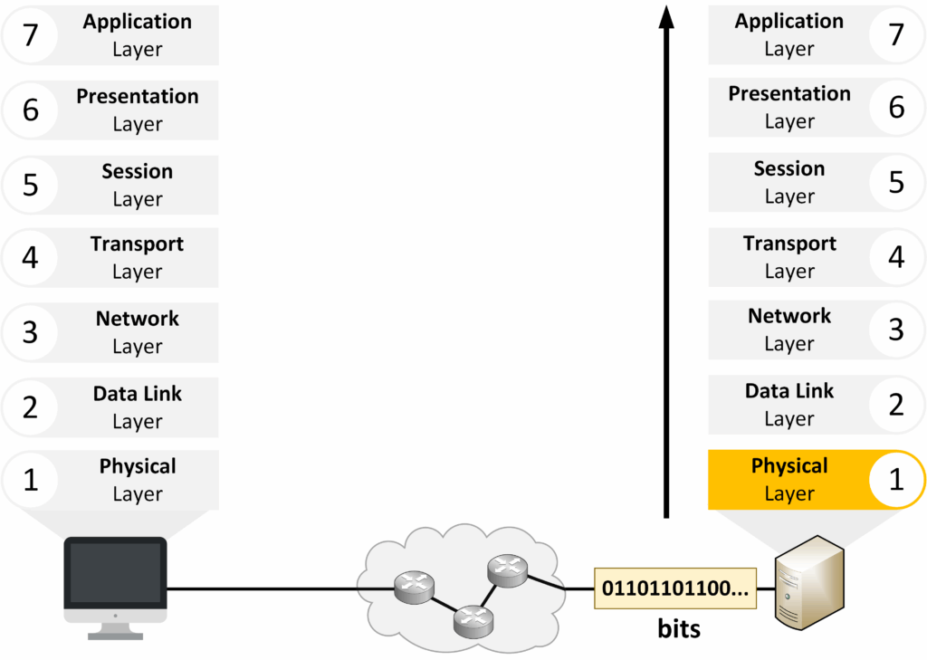
Figure 1 – Start of the De-encapsulation Process
Layer 2 – Data Link
The Data Link Layer groups the bits into a frame, verifies it using the FCS, and removes the Layer 2 header (MAC addresses). It then passes the packet to the Network Layer.
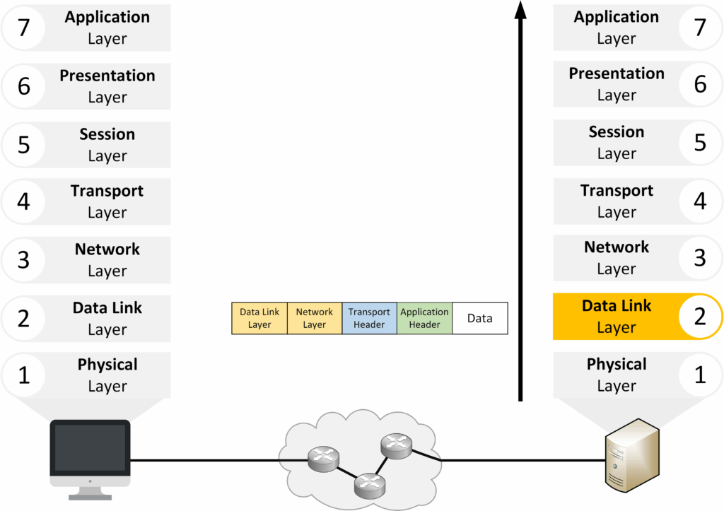
Figure 2 – OSI Layer 2: Data Link Layer in De-encapsulation
Layer 3 – Network
The Network Layer processes the packet, removes the IP header, and checks the source and destination addresses. It forwards the segment to the Transport Layer.
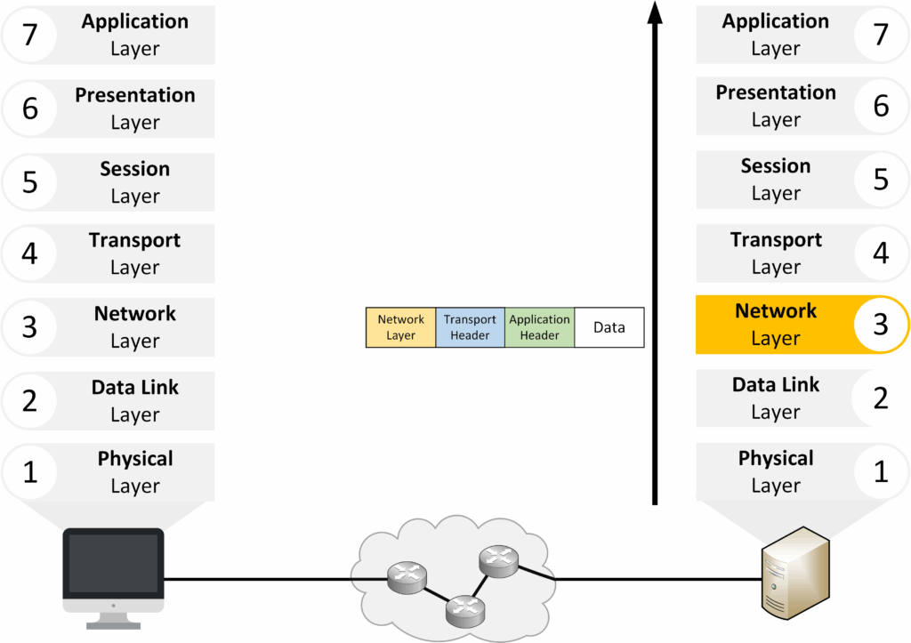
Figure 3 – OSI Layer 3: Network Layer in De-encapsulation
Layer 4 – Transport
The Transport Layer reassembles the segments into the original data stream. It removes the Layer 4 header (port numbers, reliability info) and identifies the correct service.
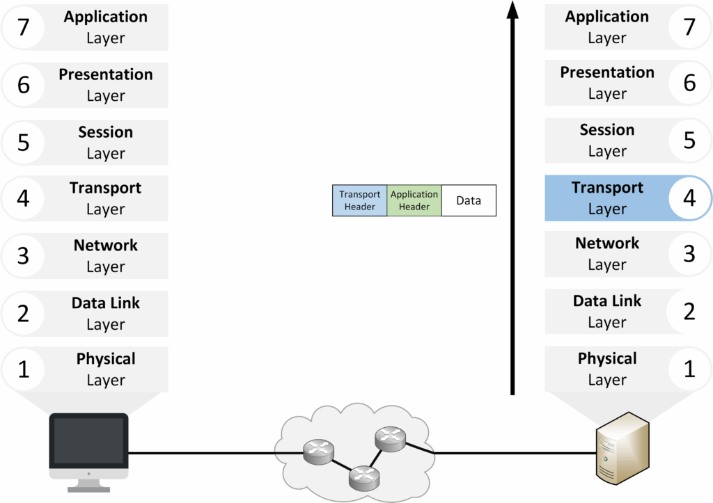
Figure 4 – OSI Layer 4: Transport Layer in De-encapsulation
Layers 5 to 7 – Upper Layers
Once the lower layers finish processing, the data moves into the upper layers of the OSI model: Session, Presentation, and Application. These layers make sure the data is correctly managed, formatted, and delivered to the right application.
Layer 5 – Session
The Session Layer establishes, maintains, and ends the communication session between devices. It keeps track of the session until the transfer is complete.
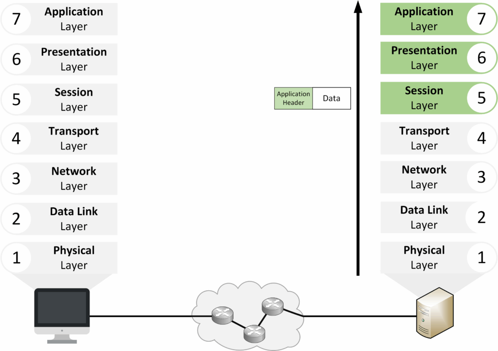
Figure 5 – De-encapsulation in the Upper OSI Layers
Layer 6 – Presentation
The Presentation Layer ensures the data is in a usable format. It may handle translation, compression, or encryption/decryption before passing the data to the application.
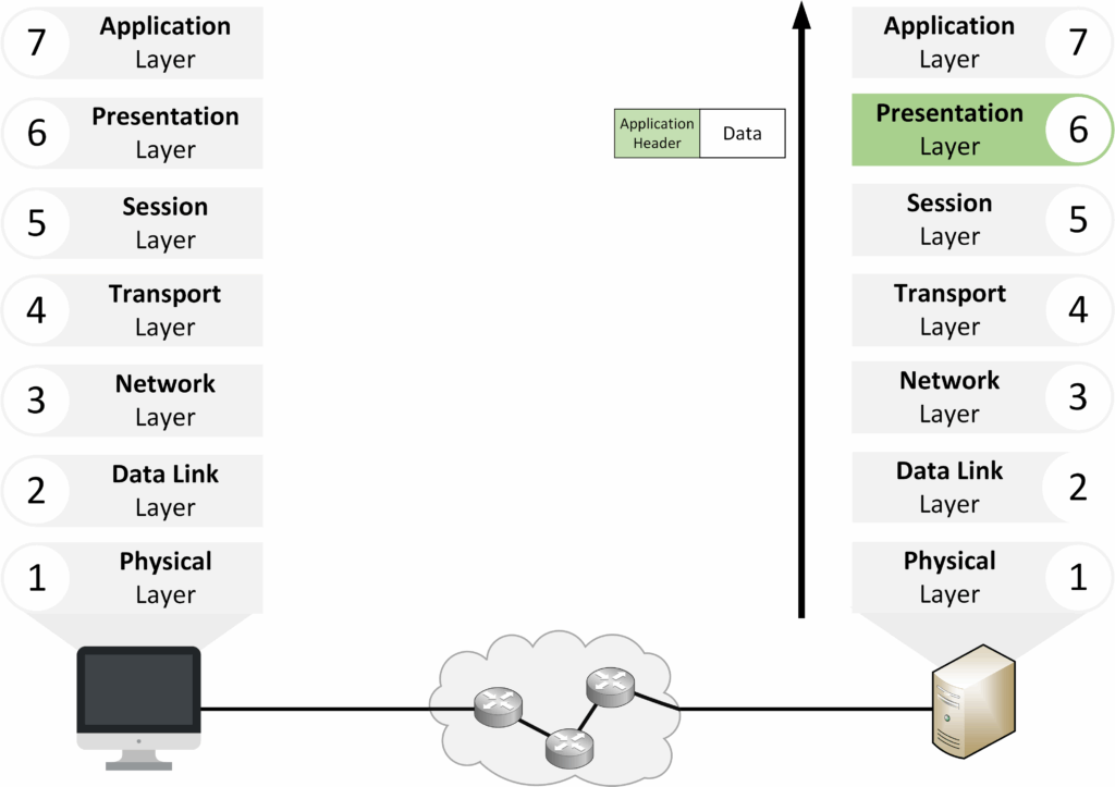
Figure 6 – OSI Layer 6: Presentation Layer in De-encapsulation
Layer 7 – Application
The Application Layer delivers the final data to the software the user interacts with, such as a browser, email client, or file transfer tool.
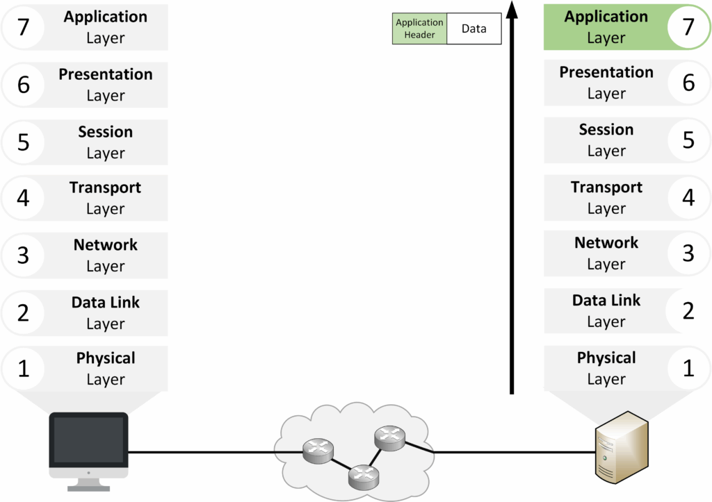
Figure 7 – OSI Layer 7: Application Layer in De-encapsulation
After understanding encapsulation and decapsulation, the next step is to see how OSI layers interact locally and between devices.
Answer the question below
Which OSI layer uses IP addresses for routing?
The OSI model describes not only the responsibilities of each layer but also how layers interact.
There are two main types of interaction: adjacent-layer and same-layer.Adjacent-layer interaction
This occurs between two layers next to each other on the same device.
Each layer either passes data down to the one below or receives data up from the one above.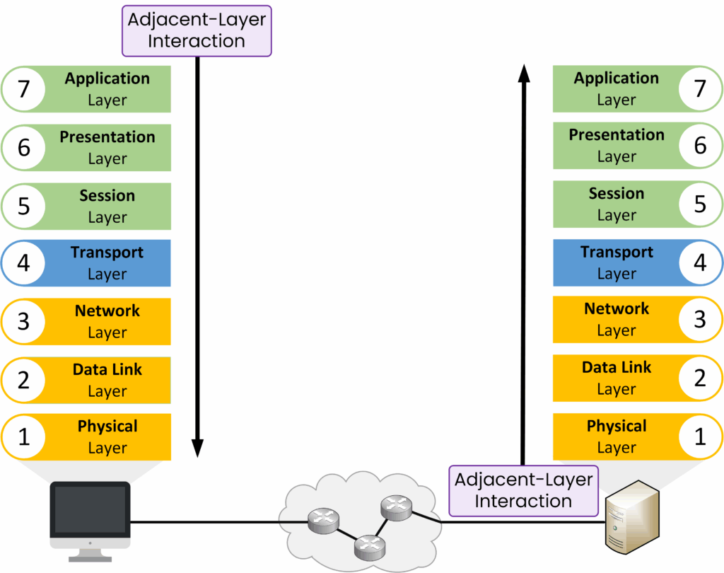
Figure 8 – Adjacent-Layer Interaction in the OSI Model
Example: The Transport Layer sends a segment down to the Network Layer.
Allows the upper layer to rely on the lower layer for specific delivery functions.
Same-layer interaction
This occurs between the same OSI layer on two different devices.
It ensures that both devices understand the data in the same way.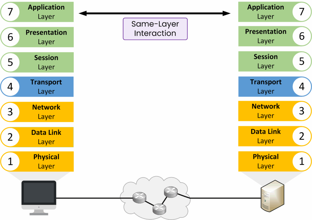
Figure 9 – Same-Layer Interaction in the OSI Model
The Transport Layer on one device talks to the Transport Layer on another device.
Maintains consistency and compatibility in communication protocols.
Answer the question below
Communication between the same layer on two devices is called same-layer or adjacent-layer interaction?
As data moved down the sender’s OSI model, each layer added control information. Each step produced a specific type of Protocol Data Unit (PDU).
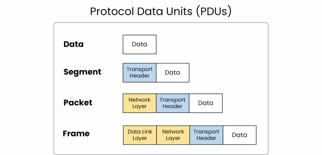
Figure 10 – Protocol Data Units (PDUs) at Different OSI Layers
PDU Types Across OSI Layers
Layer 4 – Transport → Segment (contains port numbers and reliability info, e.g., TCP or UDP).
Layer 3 – Network → Packet (adds source and destination IP addresses for routing).
Layer 2 – Data Link → Frame (adds MAC addresses and error detection with FCS).
Layer 1 – Physical → Bits (1s and 0s transmitted as electrical, optical, or radio signals).
Answer the question below
What is the PDU at Layer 2 of the OSI model?
The OSI model gives you a clear way to understand how data flows across a network. It also provides a structured method to troubleshoot issues layer by layer, helping you quickly locate and solve problems.
But here’s the key question:
If OSI is just a reference model, which model actually powers the Internet today?
In the next lesson, we’ll explore the TCP/IP model, the real foundation of modern networking, and see how it works alongside OSI in practice.
Answer the question below
Which model is the real foundation of modern networking?