Unlike LACP, which is an open standard, PAgP (Port Aggregation Protocol) is a Cisco proprietary protocol used for link aggregation.
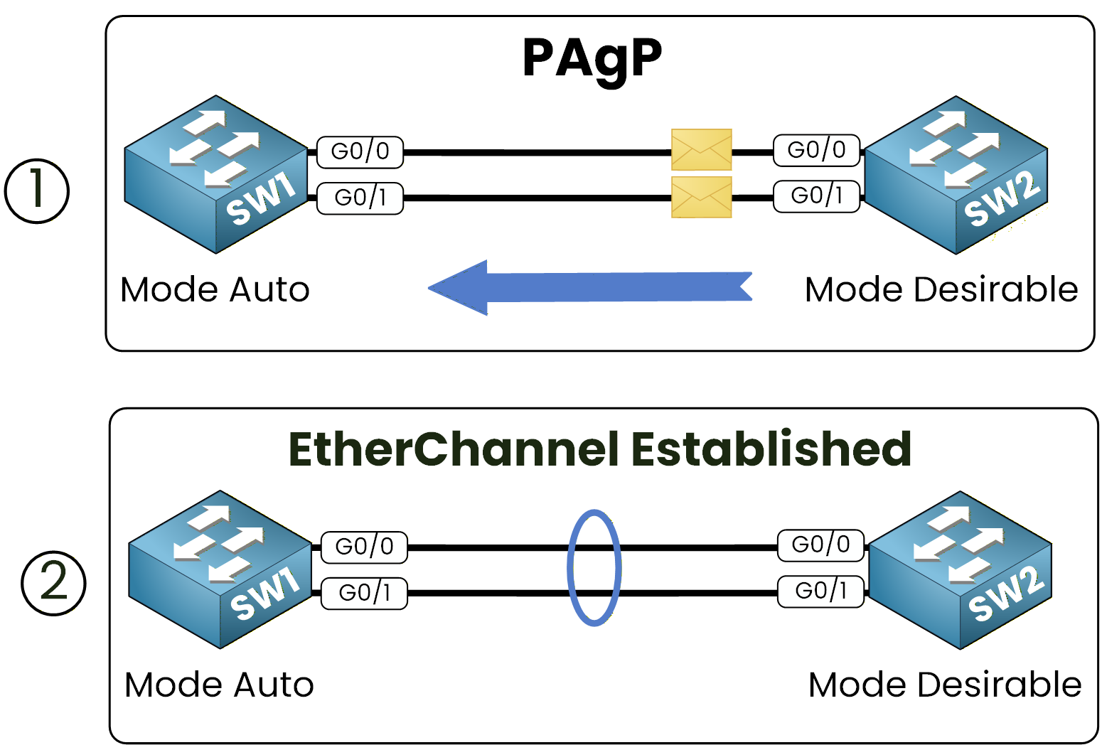
Figure 1 – Introduction to PAgP (Port Aggregation Protocol)
Interfaces are dynamically grouped using desirable or auto modes. This configuration will also include setting up interfaces as trunks and allowing VLAN 50 on the trunk.
Prerequisites for Configuration
Before starting, ensure the following conditions are met:
Interface Consistency: All interfaces in the EtherChannel must have the same speed, duplex, and interface type.
VLAN and Trunking: For Layer 2 links, interfaces must be in the same VLAN or have identical trunk settings.
Active Links: Ensure that each physical link is operational.
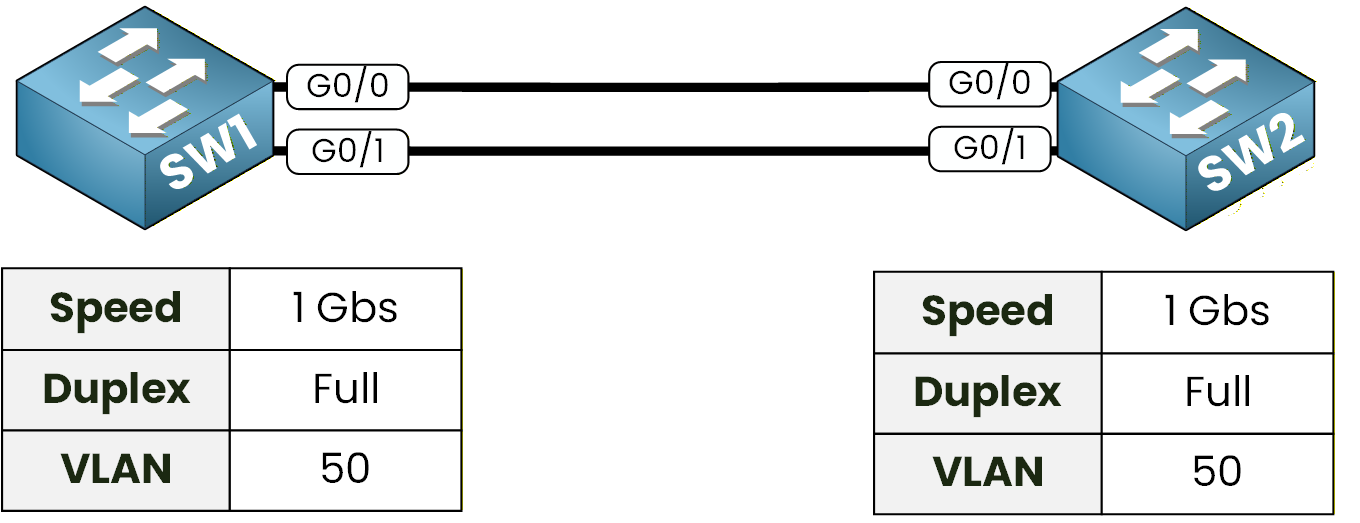
Figure 2 – PAgP Configuration Prerequisites
For this configuration, we will use GigabitEthernet interfaces in full-duplex mode, and we will allow VLAN 50 on the trunk link.
Answer the question below
Click 'Complete' to continue
In this section, we configure an EtherChannel using Cisco's proprietary Port Aggregation Protocol (PAgP).
This allows multiple physical links to be bundled into a single logical link, providing redundancy and increased bandwidth.After forming the EtherChannel, the logical interface is configured as a trunk allowing VLAN 50.
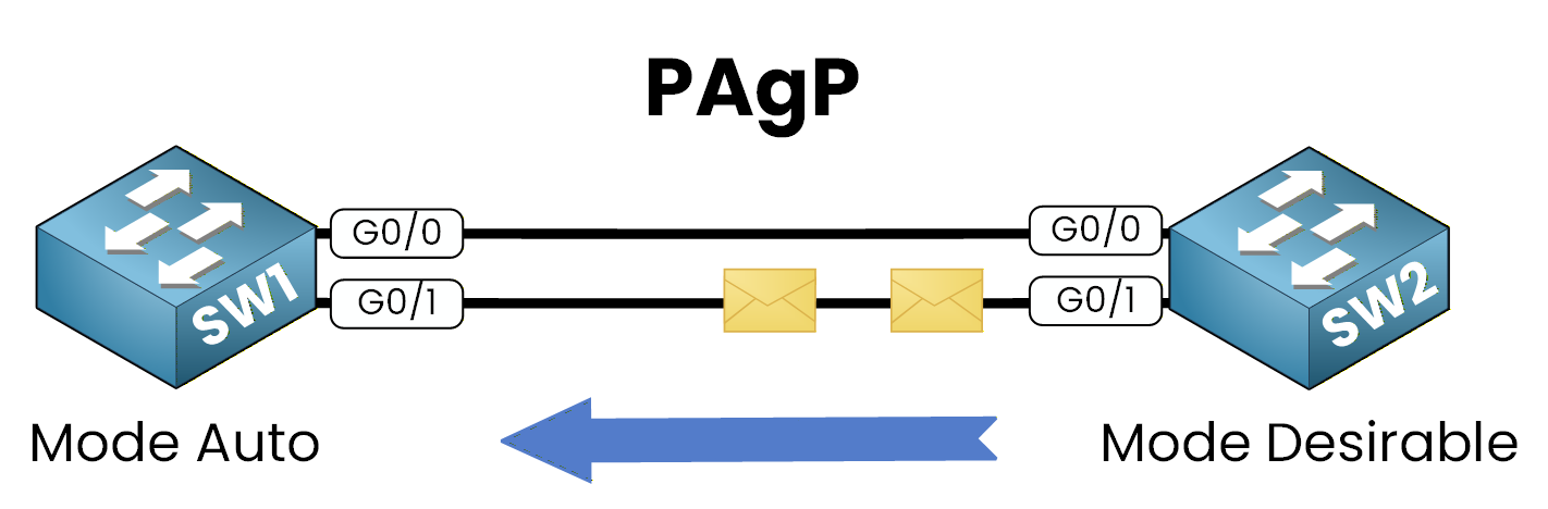
Figure 3 – PAgP EtherChannel Configuration: Auto and Desirable Modes
Configuration on SW1
Step 1: Enter Interface Configuration Mode
Select the physical interfaces that will form the EtherChannel.
SW1(config)# interface range g0/0-1Step 2: Enable PAgP (Auto Mode)
On SW1, PAgP is configured in auto mode, meaning the switch passively waits for a PAgP negotiation request.
SW1(config-if-range)# channel-group 1 mode auto
Creating a port-channel interface Port-channel 1
%LINK-5-CHANGED: Interface Port-channel1, changed state to up
%LINEPROTO-5-UPDOWN: Line protocol on Interface Port-channel1, changed state to up
SW1(config-if-range)# exit
After this command, a logical interface called Port-Channel 1 (Po1) is automatically created.
Step 3: Configure the Port-Channel as a Trunk
Configure the logical interface as an 802.1Q trunk and allow VLAN 50.
SW1(config)# interface port-channel 1
SW1(config-if)# switchport trunk encapsulation dot1q
SW1(config-if)# switchport mode trunk
SW1(config-if)# switchport trunk allowed vlan 50
These commands configure Port-Channel 1 as a trunk, enable 802.1Q encapsulation for VLAN tagging, and allow VLAN 50 to pass through the trunk.
Configuration on SW2
Now, we apply the same EtherChannel principle, but SW2 is configured to operate in PAgP desirable mode, meaning it actively initiates the PAgP negotiation.
SW2(config)# interface range g0/0-1
SW2(config-if-range)# channel-group 1 mode desirable
Creating a port-channel interface Port-channel 1
%LINK-5-CHANGED: Interface Port-channel1, changed state to up
%LINEPROTO-5-UPDOWN: Line protocol on Interface Port-channel1, changed state to up

SW2(config)# interface port-channel 1
SW2(config-if)# switchport trunk encapsulation dot1q
SW2(config-if)# switchport mode trunk
SW2(config-if)# switchport trunk allowed vlan 50
Key Point
PAgP EtherChannel forms successfully because auto and desirable modes are compatible, allowing negotiation between the two switches.
Answer the question below
In PAgP, which mode actively starts the negotiation: desirable or auto?
Answer the question below
SW1 stays in PAgP auto and SW2 is also set to auto: how many of the two switches send a negotiation request?
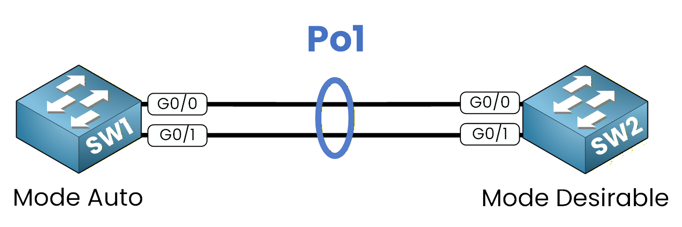
Figure 4 – Verifying PAgP EtherChannel Formation (Po1)
To ensure that the EtherChannel has formed correctly, use the
show etherchannel summarycommand on both switches.SW1
SW1# show etherchannel summary
Flags:  D - down        P - in port-channel
        I - stand-alone s - suspended
        H - Hot-standby (LACP only)
        R - Layer3      S - Layer2
        U - in use      f - failed to allocate aggregator
        u - unsuitable for bundling
        w - waiting to be aggregated
        d - default port

Group  Port-channel  Protocol    Ports
------ ------------- ----------- ----------------------------------------------
1      Po1(SU)       PAgP        Gi0/0(P) Gi0/1(P)
The output confirms that Port-Channel 1 (Po1) is active and operational in Layer 2 mode (S, U) using the PAgP protocol, with interfaces Gi0/0 and Gi0/1 successfully included in the EtherChannel.
SW2
SW2# show etherchannel summary
Flags:  D - down        P - in port-channel
        I - stand-alone s - suspended
        H - Hot-standby (LACP only)
        R - Layer3      S - Layer2
        U - in use      f - failed to allocate aggregator
        u - unsuitable for bundling
        w - waiting to be aggregated
        d - default port

Group  Port-channel  Protocol    Ports
------ ------------- ----------- ----------------------------------------------
1      Po1(SU)       PAgP        Gi0/0(P) Gi0/1(P)
The output verifies that Port-Channel 1 (Po1) is active in Layer 2 mode (S, U) using the PAgP protocol, with interfaces Gi0/0 and Gi0/1 successfully included in the EtherChannel.
Verify the Trunk Configuration
To confirm the trunk is correctly configured and that VLAN 50 is allowed, use the show interfaces trunk command.
SW1
SW1# show interfaces trunk
Port        Mode         Encapsulation  Status        Native vlan
Po1         on           802.1q         trunking      1

Port        Vlans allowed on trunk
Po1         50
SW2
SW2# show interfaces trunk
Port        Mode         Encapsulation  Status        Native vlan
Po1         on           802.1q         trunking      1

Port        Vlans allowed on trunk
Po1         50
The output verifies that Port-Channel 1 (Po1) is active as a trunk with 802.1q encapsulation and VLAN 50 is successfully permitted on the trunk, confirming that the PAgP Cisco EtherChannel is working as expected.
Answer the question below
Which command checks if the EtherChannel is working?
Answer the question below
Po1 shows the S flag as a Layer 2 bundle: which legend letter would replace it for a Layer 3 port-channel?
The PAgP Cisco configuration is complete.
Both switches are now using PAgP Cisco EtherChannel on Port-Channel 1, which aggregates the two physical interfaces into one logical link.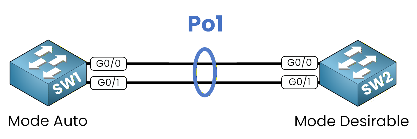
Figure 5 – PAgP EtherChannel Conclusion (Po1)
Answer the question below
Click 'Complete' to continue