Imagine a small company expanding its local network. To improve reliability, the administrator connects the switches using multiple redundant links. A few minutes later, users start complaining, the network becomes slow, pings time out, and broadcast traffic floods the LAN.
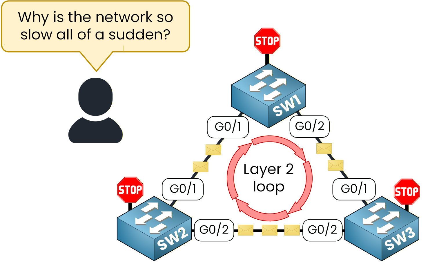
Figure 1 – Example of a Layer 2 loop created
What happened?
The network has fallen into a Layer 2 loop, a classic issue that can bring even simple Ethernet topologies to a halt. Frames endlessly circulate between switches because there’s no mechanism to stop them.
This is exactly the kind of disaster Spanning Tree Protocol (STP) was designed to prevent. STP ensures that even if multiple links exist between switches, only one logical path remains active. The others are placed in a blocking state to avoid loops but can reactivate instantly if a failure occurs.In this lab, you’ll learn how to configure the Spanning Tree Protocol and how to control which switch becomes the Root Bridge, the central decision-maker in any STP topology.
Network Topology Overview
Now that you understand why STP is necessary, let’s see how to configure it in practice.
Here is the topology you will use:SW1 as the Root Bridge
SW2 as the Backup Root Bridge
SW3 with Default priority switch serving as a NON-ROOT switch
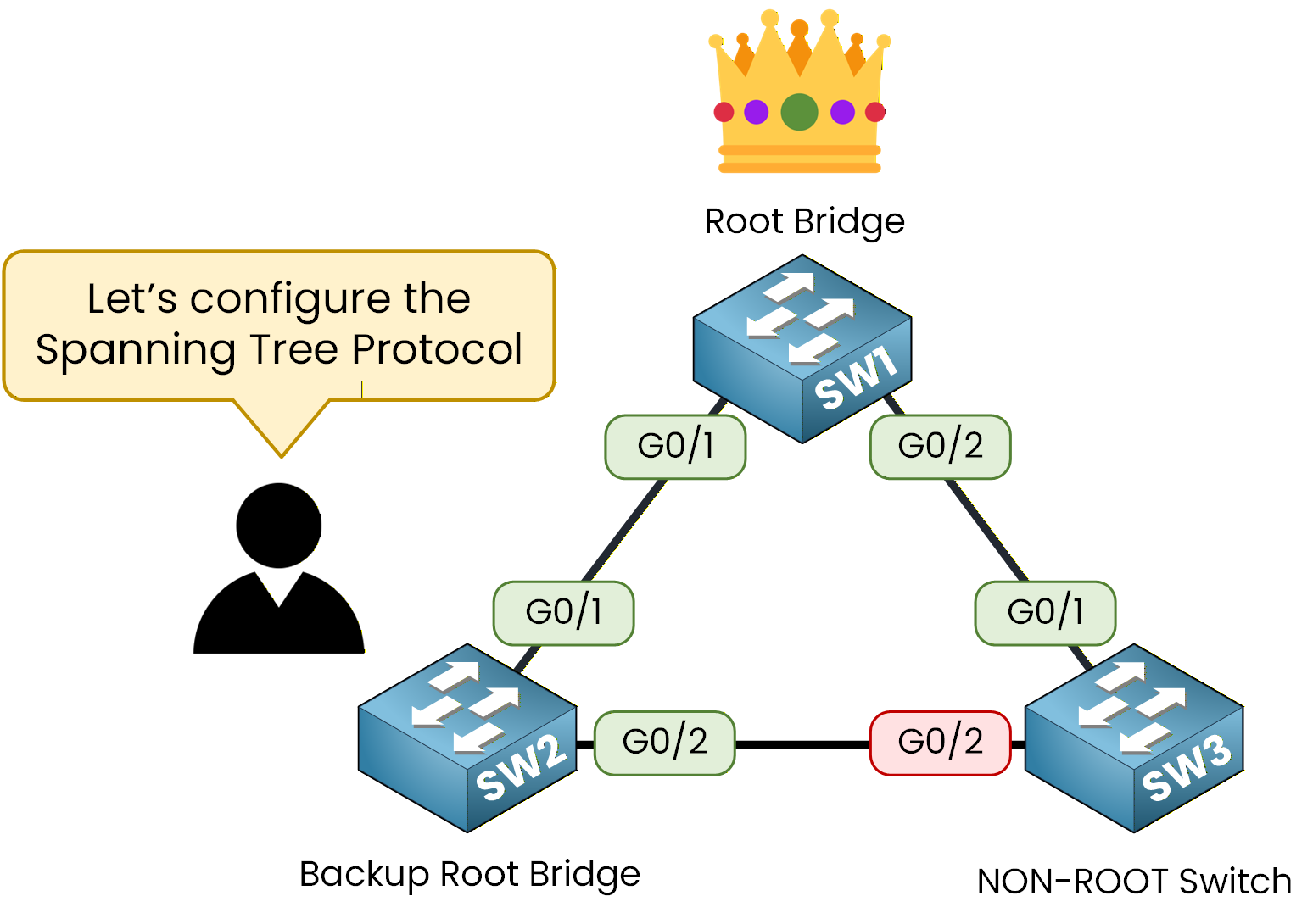
Figure 2 – Three-switch topology with Root, Backup, and Non-Root switches.
The term Backup Root Bridge may be new for you.
Don’t worry, in this lab, you’ll see exactly what it does and why we use it in an STP topology.Lab Overview
Here’s the structure we’ll follow throughout this lab:
Step 1 – Identify the current STP election
Step 2 – Configure SW1 as the Root Bridge
Step 3 – Configure SW2 as the Backup Root Bridge
Step 4 – Observe STP blocked linkLet’s Get Started
In the next sections, we’ll walk through each configuration step together, explain the commands, and verify that everything works correctly.
Answer the question below
These three switches are connected to each other. Even though we haven’t configured anything yet, STP is already running on all of them.
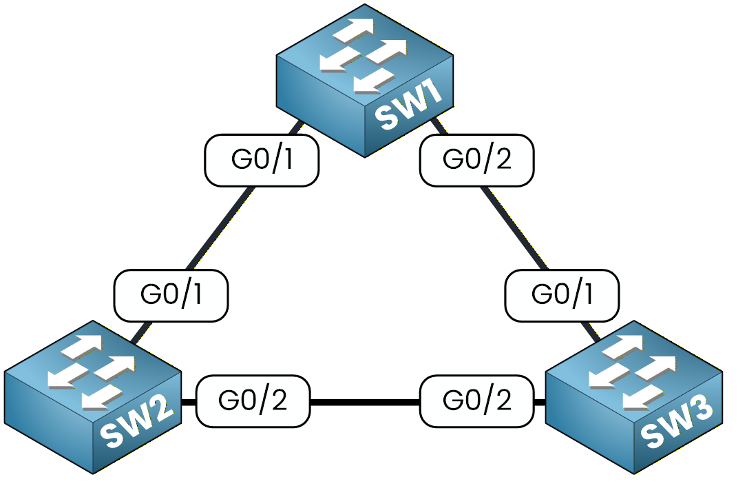
Figure 3 - Spanning Tree Topology
Your first goal is simple: observe how STP behaves by default and identify which switch is currently acting as the Root Bridge.
Let’s begin with SW1.
Check the Default Configuration
On SW1, enter the following command:
SW1# show running-config
Building configuration...

Current configuration : 1077 bytes
!
version 15.0
no service timestamps log datetime msec
no service timestamps debug datetime msec
no service password-encryption
!
hostname SW1
!
!
!
!
!
!
spanning-tree mode pvst
spanning-tree extend system-id
In the output, you will see the following lines:
spanning-tree mode pvst
spanning-tree extend system-id
As you can see, even before configuring anything, Cisco switches already have PVST enabled by default.
You might be asking yourself what PVST is, because we haven’t talked about it yet.What is PVST?
PVST, or Per VLAN Spanning Tree, is the default STP mode.
It creates one spanning tree instance per VLAN.
This means that if your network has multiple VLANs, you will have multiple spanning tree instances running.In our case, we only have VLAN 1, so we only have one instance of STP to look at.
Now let’s check how STP is behaving on this switch.
Type the following command:SW1# show spanning-tree ? active Report on active interfaces only detail Detailed information inconsistentports Show inconsistent ports interface Spanning Tree interface status and configuration summary Summary of port states vlan VLAN Switch Spanning Trees <cr>You will see several options.
We want to inspect VLAN 1, so run:SW1# show spanning-tree vlan 1 VLAN0001 Spanning tree enabled protocol ieee Root ID Priority 32769 Address 0001.63A6.E107 Cost 4 Port 25(GigabitEthernet0/1) Hello Time 2 sec Max Age 20 sec Forward Delay 15 sec Bridge ID Priority 32769 (priority 32768 sys-id-ext 1) Address 0060.7085.E6B0 Hello Time 2 sec Max Age 20 sec Forward Delay 15 sec Aging Time 20 Interface Role Sts Cost Prio.Nbr Type ---------------- ---- --- --------- -------- -------------------------------- Gi0/1 Root FWD 4 128.25 P2p Gi0/2 Desg FWD 4 128.26 P2pThere are several interesting elements here.
Let’s look at two of them.The Root ID section shows the information of the switch that STP has selected as the Root Bridge.
The Bridge ID section shows the information of the switch you are currently on, which is SW1.
You can see that the priority value is equal to the configured priority plus the system ID extension, which in this case is 1 because we are in VLAN 1.
At the bottom of the output, you can see the STP timers, but we will not discuss them now. You will learn about them later in the course.
Answer the question below
Now let’s look at SW2.
SW2# show spanning-tree vlan 1
VLAN0001
  Spanning tree enabled protocol ieee
  Root ID    Priority    32769
             Address     0001.63A6.E107
             This bridge is the root
             Hello Time  2 sec  Max Age 20 sec  Forward Delay 15 sec

  Bridge ID  Priority    32769  (priority 32768 sys-id-ext 1)
             Address     0001.63A6.E107
             Hello Time  2 sec  Max Age 20 sec  Forward Delay 15 sec
             Aging Time  20

Interface        Role Sts Cost      Prio.Nbr Type
---------------- ---- --- --------- -------- --------------------------------
Gi0/1            Desg FWD 4         128.25   P2p
Gi0/2            Desg FWD 4         128.26   P2p
Here, SW2 is the root bridge, as indicated by the message "This bridge is the root".
The Root ID and Bridge ID match, confirming that SW2 is currently controlling the spanning tree.
Next, let’s check SW3:SW3# show spanning-tree vlan 1 VLAN0001 Spanning tree enabled protocol ieee Root ID Priority 32769 Address 0001.63A6.E107 Cost 4 Port 26(GigabitEthernet0/2) Hello Time 2 sec Max Age 20 sec Forward Delay 15 sec Bridge ID Priority 32769 (priority 32768 sys-id-ext 1) Address 0090.2BE2.8EE9 Hello Time 2 sec Max Age 20 sec Forward Delay 15 sec Aging Time 20 Interface Role Sts Cost Prio.Nbr Type ---------------- ---- --- --------- -------- -------------------------------- Gi0/2 Root FWD 4 128.26 P2p Gi0/1 Altn BLK 4 128.25 P2pIn this output, you will notice something important.
One of the ports, Gi0/1, is in the Altn BLK state. This means the port is blocked.This behaviour makes sense for our topology.
Because SW2 is the Root Bridge, STP must block one of the redundant links on the non-root switches.
On SW3, STP decided to block Gi0/1 to prevent a Layer 2 loop.This gives us the initial spanning tree topology, where SW2 is the Root Bridge.
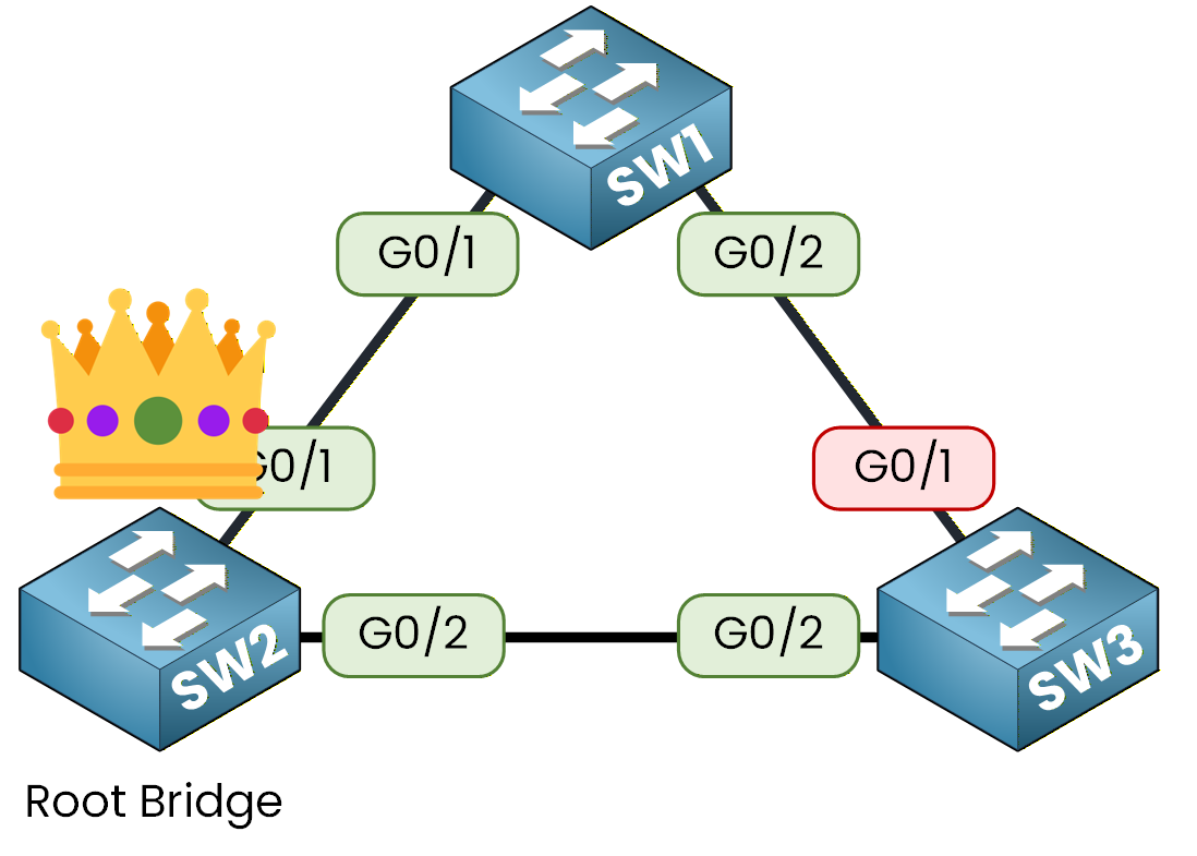
Figure 4 - Spanning Tree Initial Topology
40 % Complete: you’re making great progress
Ready to pass your CCNA exam?