In this lab, you will learn how to configure 802.1Q trunking between two switches so VLANs can extend across multiple devices.
This is the topology we will use to practice the concept of 802.1Q Trunking.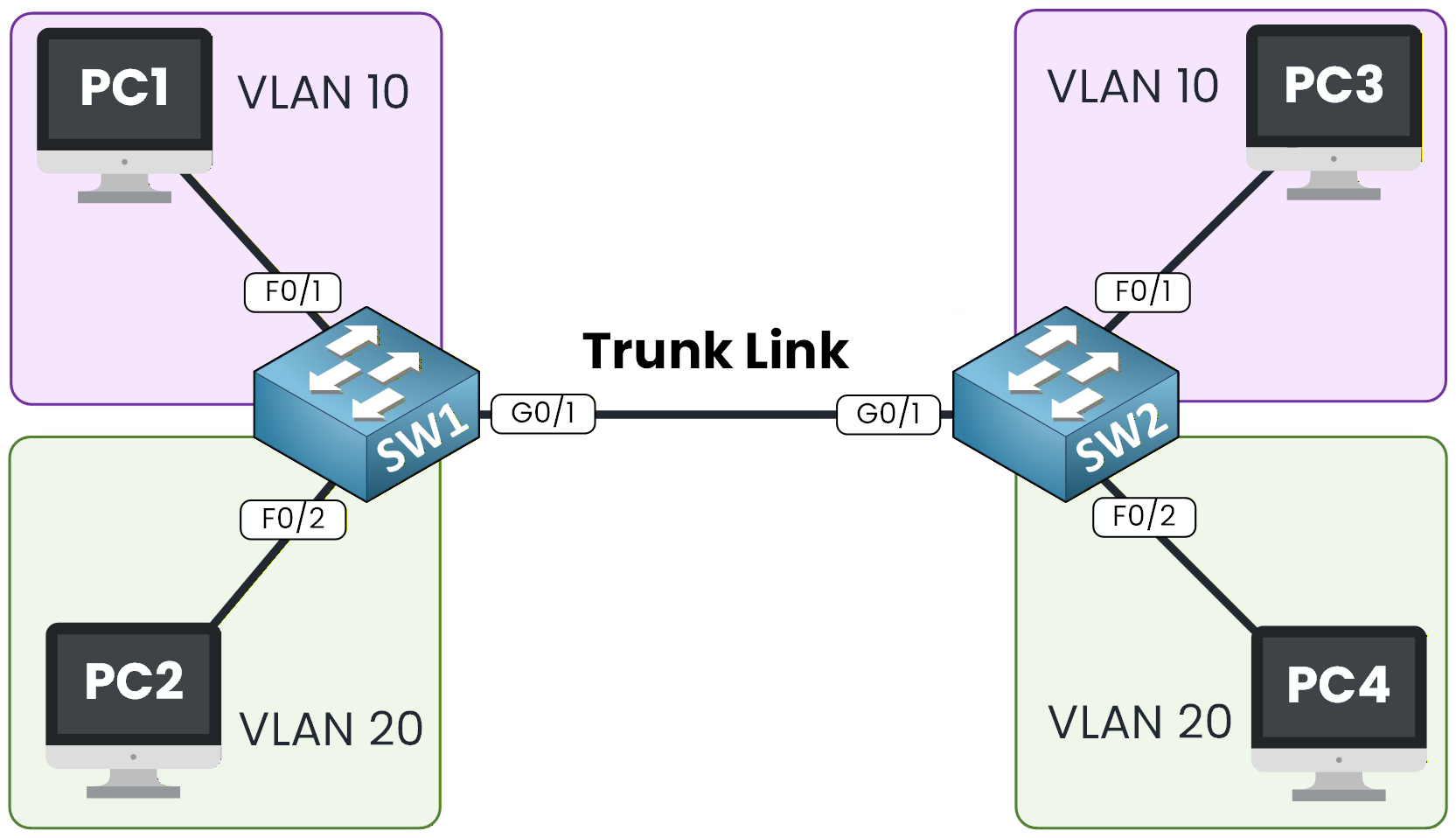
Figure 1 - 802.1Q Configuration Topology
This lab will guide you through the configuration, verification, and testing of 802.1Q trunks so you understand exactly how VLANs propagate between switches.
The topology is already preconfigured with IP addressing and switch connections, so you can focus entirely on the VLAN and trunk configuration.
How to Begin
Before starting, download the lab file using the button at the top of the page.
Your goal in this exercise is to create VLANs, assign ports, and then configure an 802.1Q trunk between SW1 and SW2.Lab Overview
Here’s the structure we will follow throughout this lab:
Step 1 – Configure VLANs and Access Ports on SW1
Step 2 – Configure VLANs and Access Ports on SW2
Step 3 – Configure 802.1Q Trunking
Step 4 – Verify Trunk BehaviorLet’s get started!
Answer the question below
To begin, we need to create the two VLANs used in this topology: VLAN 10 and VLAN 20.

Figure 2 - 802.1Q Topology Example
Create VLAN 10 and VLAN 20
The process of creating a VLAN is simple.
You only need to enter the VLAN number, and you can optionally assign a name to make the configuration easier to read.SW1# conf t Enter configuration commands, one per line. End with CNTL/Z. SW1(config)# vlan 10 SW1(config-vlan)# name Sales SW1(config-vlan)# exit SW1(config)# vlan 20 SW1(config-vlan)# name Tech SW1(config-vlan)# endThen, after creating VLAN 10 and VLAN 20, we can verify that the VLANs are present.
On the switch, type the commandshow vlan briefSW1# show vlan brief VLAN Name Status Ports ---- -------------------------------- --------- ------------------------------- 1 default active Fa0/1, Fa0/2, Fa0/3, Fa0/4 Fa0/5, Fa0/6, Fa0/7, Fa0/8 Fa0/9, Fa0/10, Fa0/11, Fa0/12 Fa0/13, Fa0/14, Fa0/15, Fa0/16 Fa0/17, Fa0/18, Fa0/19, Fa0/20 Fa0/21, Fa0/22, Fa0/23, Fa0/24 Gig0/1, Gig0/2 10 Sales active 20 Tech active 1002 fddi-default active 1003 token-ring-default active 1004 fddinet-default active 1005 trnet-default activeOur two VLANs are now created, and we must assign them to the correct ports.
Assign Ports to the Correct VLANs
We assign VLAN 10 to the interface connected to PC1, and VLAN 20 to the interface connected to PC2.
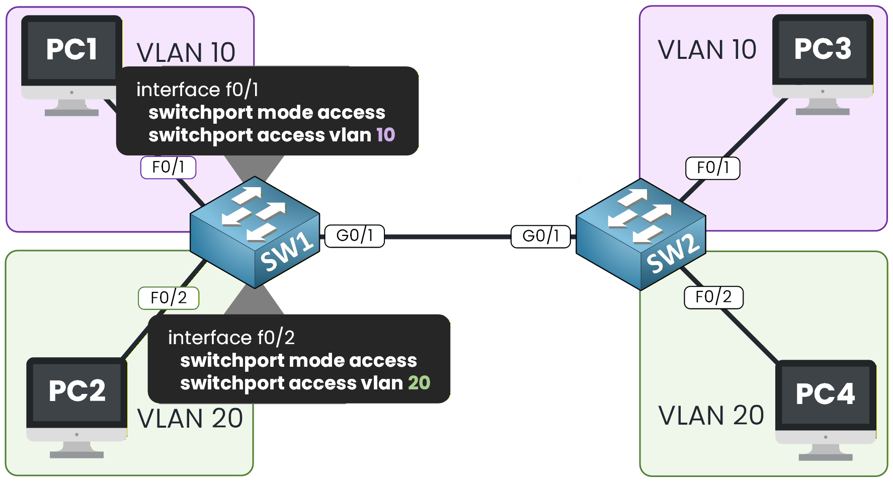
Figure 3 – VLAN Access on SW1
Take a look at Figure 3 to see how the access VLAN configuration should look.
SW1# conf t
Enter configuration commands, one per line.  End with CNTL/Z.
SW1(config)# int f0/1
SW1(config-if)# switchport mode access
SW1(config-if)# switchport access vlan 10
SW1(config-if)# exit

SW1(config)# int f0/2
SW1(config-if)# switchport mode access
SW1(config-if)# switchport access vlan 20
SW1(config-if)# end
Verify the VLAN Assignment
We can verify this again using:
SW1# show vlan brief

VLAN Name                             Status    Ports
---- -------------------------------- --------- -------------------------------
1    default                          active    Fa0/3, Fa0/4, Fa0/5, Fa0/6
                                                Fa0/7, Fa0/8, Fa0/9, Fa0/10
                                                Fa0/11, Fa0/12, Fa0/13, Fa0/14
                                                Fa0/15, Fa0/16, Fa0/17, Fa0/18
                                                Fa0/19, Fa0/20, Fa0/21, Fa0/22
                                                Fa0/23, Fa0/24, Gig0/1, Gig0/2
10   Sales                            active    Fa0/1
20   Tech                             active    Fa0/2
1002 fddi-default                     active
1003 token-ring-default               active
1004 fddinet-default                  active
1005 trnet-default                    active
Perfect, the PCs are now assigned to the correct VLANs.
We need to do the same on SW2 before going on the 802.1Q Configuration.Answer the question below
Which command assigns interface Fa0/1 to VLAN 10?
Now let’s do the exact same configuration on SW2.
Just like before, we need to create VLAN 10 and VLAN 20, then assign the correct interfaces to each VLAN.Create VLAN 10 and VLAN 20
SW2# conf t
Enter configuration commands, one per line.  End with CNTL/Z.
SW2(config)# vlan 10
SW2(config-vlan)# name Sales
SW2(config-vlan)# exit

SW2(config)# vlan 20
SW2(config-vlan)# name Tech
SW2(config-vlan)# exit
At this point, both VLANs exist on the switch but have no ports assigned to them yet.
Assign Ports to the Correct VLANs
According to Figure 4, we can see that PC3 is in VLAN 10, and PC4 is in VLAN 20. So we need to make sure we apply the vlan on the correct interface.
The appropriate commands are shown below.
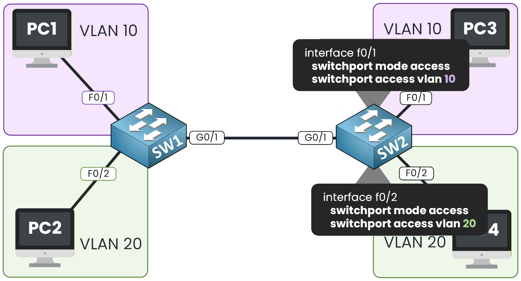
Figure 4 – VLAN Access on SW2
Let's do that on SW2.
SW2(config)# int f0/1
SW2(config-if)# switchport mode access
SW2(config-if)# switchport access vlan 10
SW2(config-if)# exit

SW2(config)# int f0/2
SW2(config-if)# switchport mode access
SW2(config-if)# switchport access vlan 20
SW2(config-if)# end
Verify the VLAN Assignment
We need to verify the VLAN association:
40 % Complete: you’re making great progress
Unlock the rest of this lesson
If you’d like to continue your CCNA journey, simply create your free account.
Access all CCNA lessons
Practice with hands-on labs
Train with Practice exams and Quizzes
Progress tracking in your dashboard
Made by network engineers - CCNP certified
learners globally