In Ethernet networks, multiple physical links between devices may appear to provide more bandwidth and enhance reliability.
However, this approach creates a problem.
Spanning Tree Protocol (STP) prevents Layer 2 loops by blocking redundant links.Without EtherChannel
When several parallel links exist between switches, STP disables the extra ones to avoid loops.
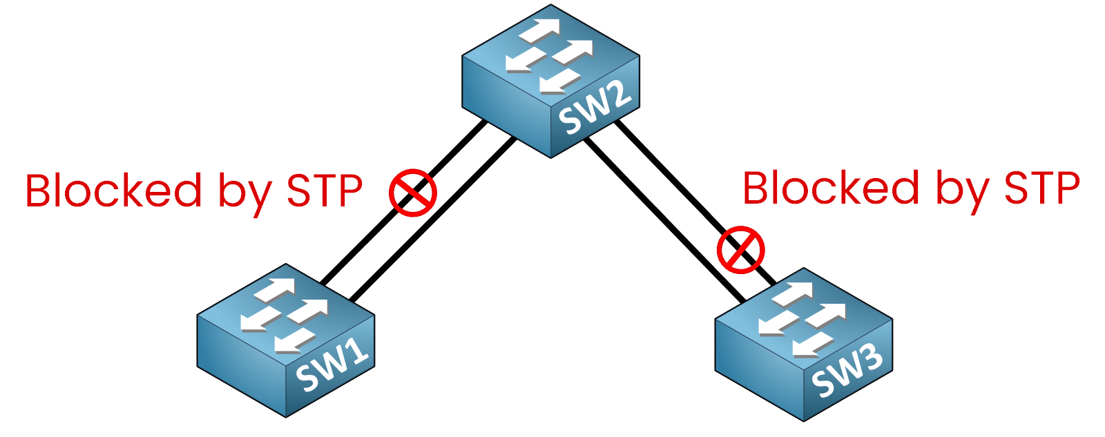
Figure 1 – Many Physical Links Without EtherChannel
🔴 Only one link per redundant pair remains active.
🔴 Extra links stay idle, wasting available bandwidth.
If we look at SW2, we can verify this behavior using the following command:
SW2# show spanning-tree

Interface        Role Sts Cost      Prio.Nbr Type
---------------- ---- --- --------- -------- ----
Gi0/1            Root FWD 4         128.1    P2p
Gi0/2            Altn BLK 4         128.2    P2p
Gi0/3            Desg FWD 4         128.3    P2p
Gi0/4            Desg FWD 4         128.4    P2p
If we examine the output on SW2, we can see that:
The interfaces highlighted in green (Gi0/1, Gi0/3 and Gi0/4) are in Forwarding (FWD) state.
The interface highlighted in red (Gi0/2) is in Blocking (BLK) state. Gi0/4 shows FWD on SW2 because SW3 blocks the other end of that link.
This means that although four physical links are connected, only two are actively forwarding traffic.
The other links remain unused due to STP.As a result, adding more physical links does not improve bandwidth utilization.
With EtherChannel
EtherChannel solves this limitation by bundling multiple physical links into a single logical channel.
From the perspective of STP, routing protocols, and the switch itself, this bundle appears as one single interface.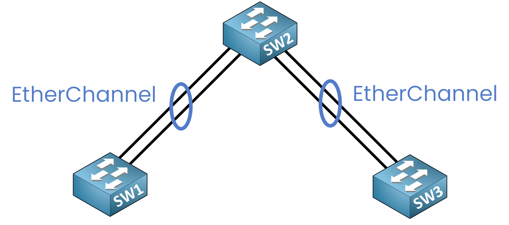
Figure 2 – EtherChannel Logical Bundling
✅ All links are active together, providing aggregated bandwidth.
✅ If one link fails, the remaining links continue forwarding traffic.
✅ STP does not block individual member links because it sees only one logical interface.
If we now look again at SW2, we observe a different result:
SW2# show spanning-tree

Interface        Role Sts Cost      Prio.Nbr Type
---------------- ---- --- --------- -------- --------------------------------
Po1              Root FWD 4         128.65   P2p
Po2              Desg FWD 4         128.66   P2p
On SW2:
STP now sees only Po1 and Po2, which are logical Port-Channel interfaces.
Both interfaces are in the Forwarding state.
No physical interface is blocked.
The individual links inside each EtherChannel bundle are all active, allowing traffic to be distributed across them while still preventing loops.
Answer the question below
STP blocks extra links to prevent what?
You can configure EtherChannel (also called a Port-Channel) in three ways:
Static EtherChannel (Manual Mode)
Static EtherChannel requires manual configuration without any protocol negotiation.
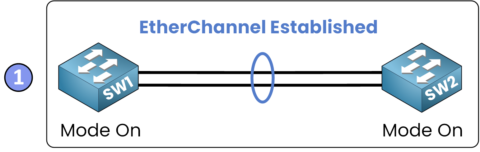
Figure 3 – Static EtherChannel (Mode On)
Both sides must be configured with explicit settings to bundle the same interfaces.
Port Aggregation Protocol (PAgP)
PAgP is a Cisco-proprietary protocol that automates the negotiation of EtherChannel formation between two devices.
It works by using modes that let two devices agree and form the EtherChannel.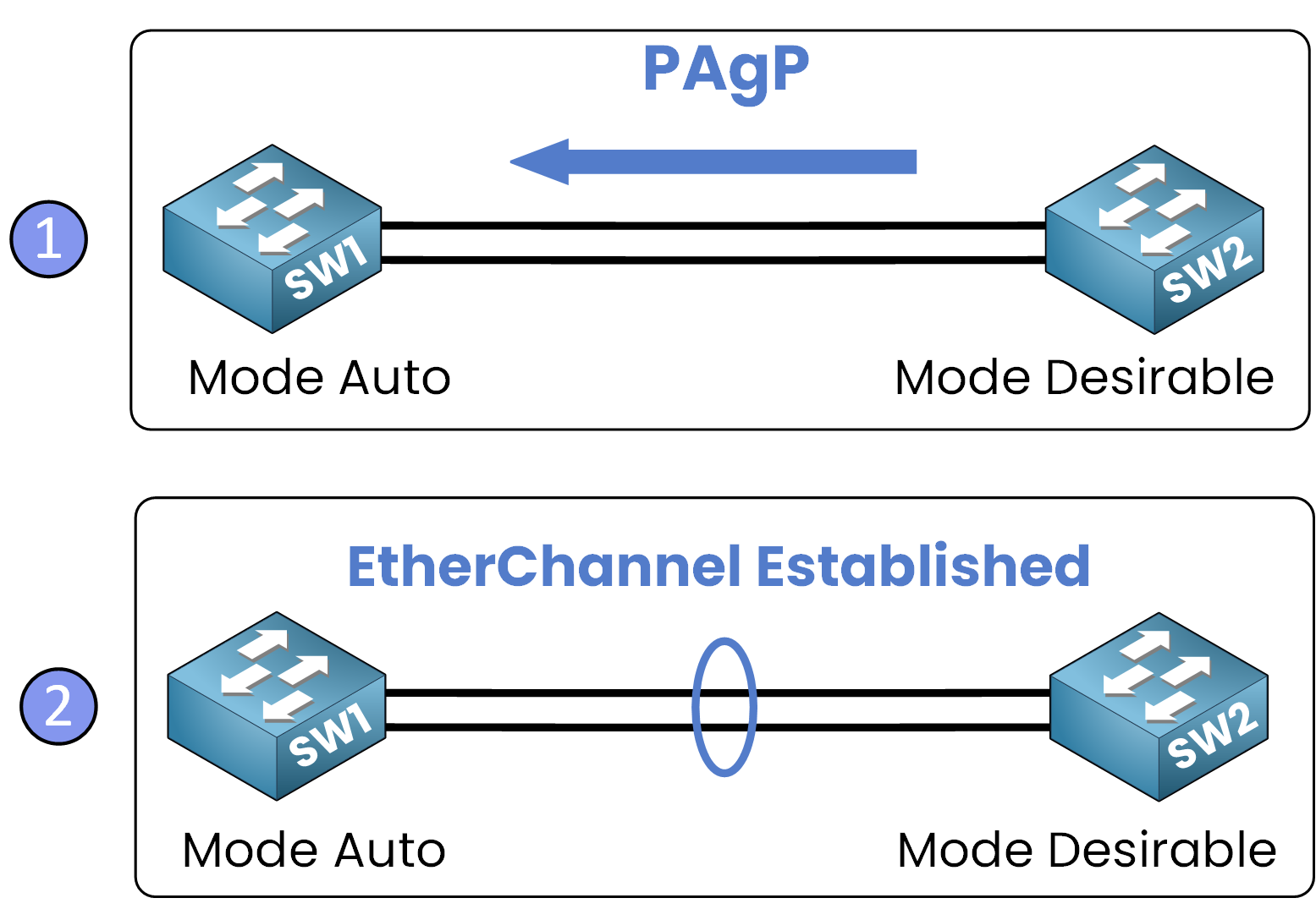
Figure 4 – PAgP (Auto / Desirable Modes)
Link Aggregation Control Protocol (LACP)
LACP (IEEE 802.3ad) allows link aggregation between devices from different vendors.
It works similarly to PAgP but follows an open standard and also uses modes to negotiate the bundle.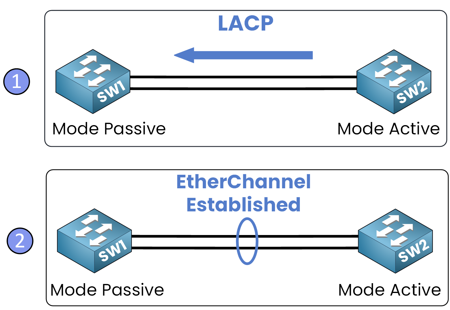
Figure 5 – LACP (Passive / Active Modes)
We'll study each method in detail in the next lessons (concepts, configuration, verification).
Answer the question below
Which EtherChannel protocol is the open standard?
You have now learned which function is provided by EtherChannel: it bundles many ports into one logical interface, so STP sees a single interface, improving bandwidth and redundancy.
There are three ways to configure an EtherChannel:
Static: Manual configuration without negotiation.
PAgP: Cisco-proprietary dynamic negotiation.
LACP: IEEE standard dynamic negotiation.
In the next lesson, we will configure Static EtherChannel step by step.
Answer the question below
Which EtherChannel method uses manual configuration without negotiation?