The OSI Model, created in the 1980s, is a framework that explains how devices communicate across a network, step by step through seven layers.
Its strength is in its layered structure. This divides communication into seven layers, each with its own responsibilities.
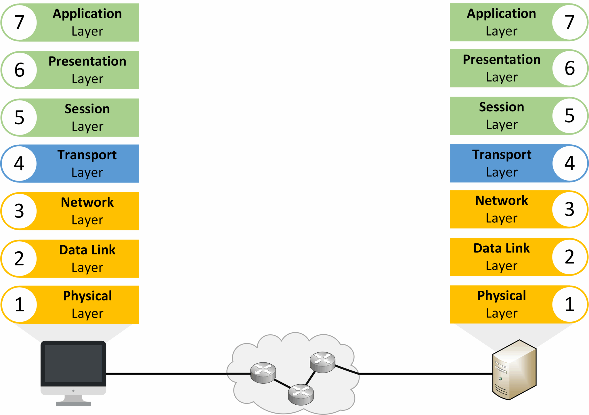
Figure 1 – OSI Model
The OSI model helps us understand network communication and troubleshoot issues. But it serves as a theoretical reference above all else. The TCP/IP model is the standard in networking. It outlines the protocols for transferring data between devices.
Answer the question below
The OSI model is built on seven layers, each with a specific role in communication.
To understand how data moves through the network, you need to know two key processes: encapsulation and decapsulation.Encapsulation
When you send data (for example, a file or a message), it travels down through the OSI layers on your device.
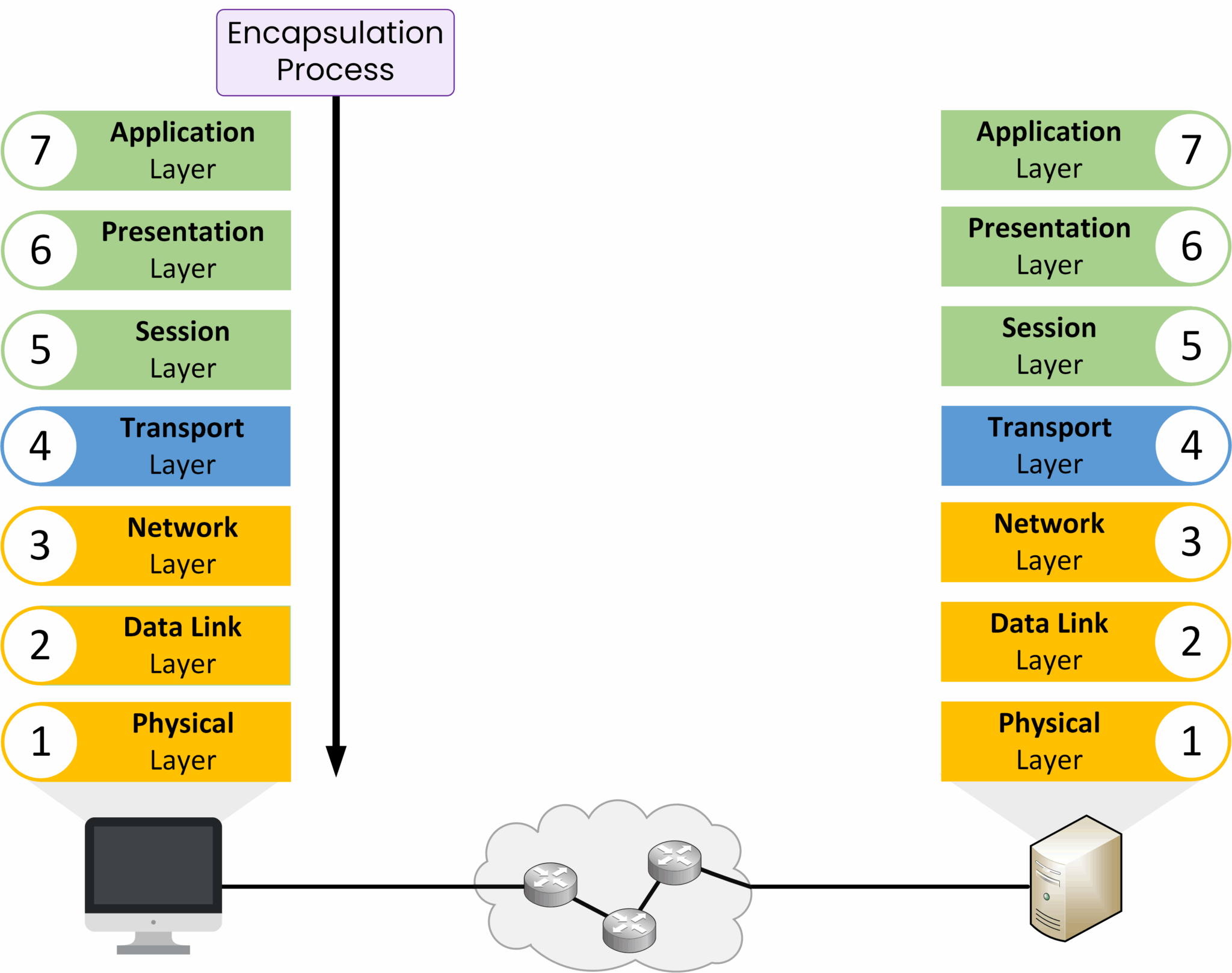
Figure 2 – Encapsulation Process in the OSI Model
At each layer, extra information is added such as addresses, port numbers, and delivery details. This ensures that the data can reach the correct destination.
Decapsulation
When the data arrives at its destination, the process is reversed. The data moves up the OSI layers, and each layer removes and interprets the information that was added by its counterpart on the sender’s side.
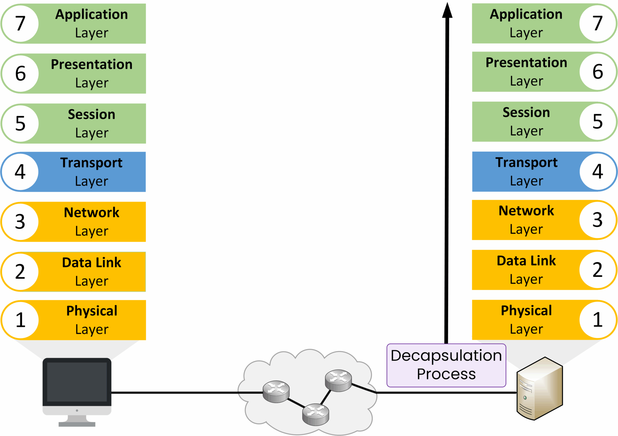
Figure 3 – Decapsulation Process in the OSI Model
Why It Matters
Encapsulation ensures the data contains all the information needed to reach its destination.
Decapsulation ensures the receiving device can interpret the data correctly and deliver it to the right application.
Now that you understand encapsulation and decapsulation, let’s look at the seven OSI layers and the role each one plays in communication.
Answer the question below
What process adds headers and trailers as data moves down the layers?
Seven layers make up the OSI model, and each has a specific function. Let’s look at them from the top (closest to the user) down to the bottom (closest to the physical network).
Layer 7 – Application
The Application Layer is where you interact with the network. You use applications like web browsers, email clients, and messaging apps. When you visit
https://pingmynetwork.com, this layer starts the request with the correct protocol.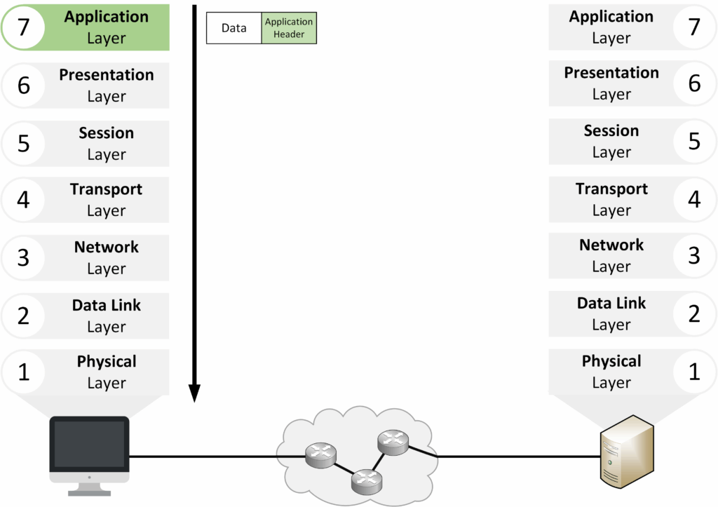
Figure 4 – OSI Layer 7: Application Layer
Key points:
Closest to the end user.
Manages application-level protocols such as HTTPS, HTTP, FTP, and SMTP.
Layer 6 – Presentation
The Presentation Layer formats the data in a way that the receiving application can use. It converts data from the application format to the network format. It can also handle encryption.
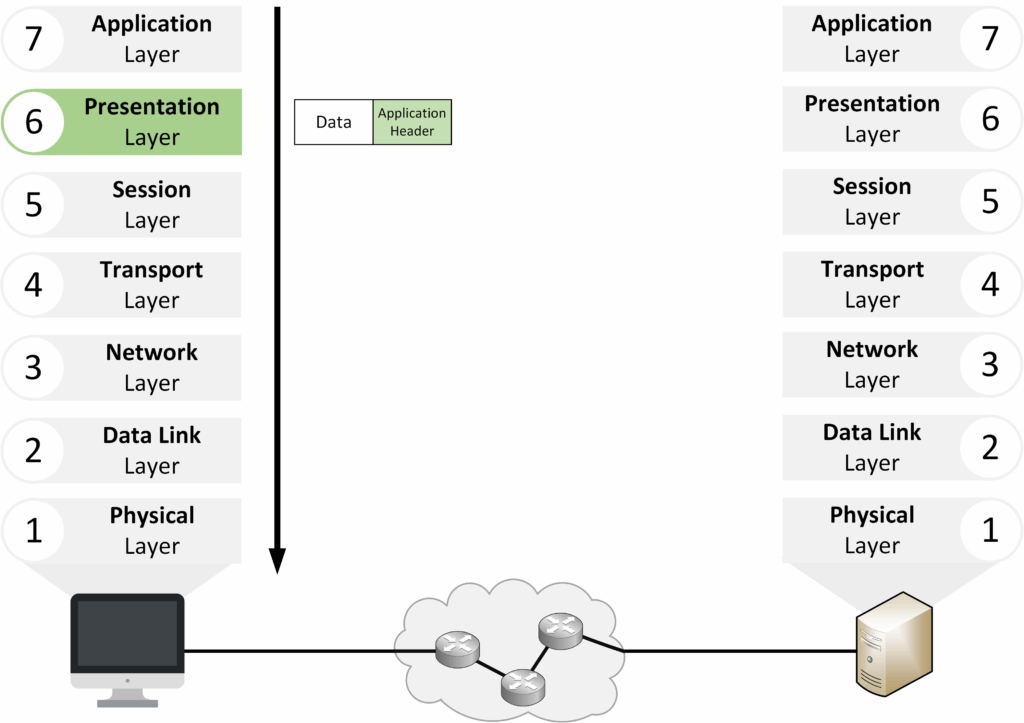
Figure 5 – OSI Layer 6: Presentation Layer
Key points:
Translates and formats data for the application.
Encrypts and decrypts data for secure communication (e.g., TLS/SSL for HTTPS).
Example: Encrypting a message before sending it, then decrypting it upon receipt.
Layer 5 – Session
The Session Layer handles starting, maintaining, and closing communication sessions between devices.
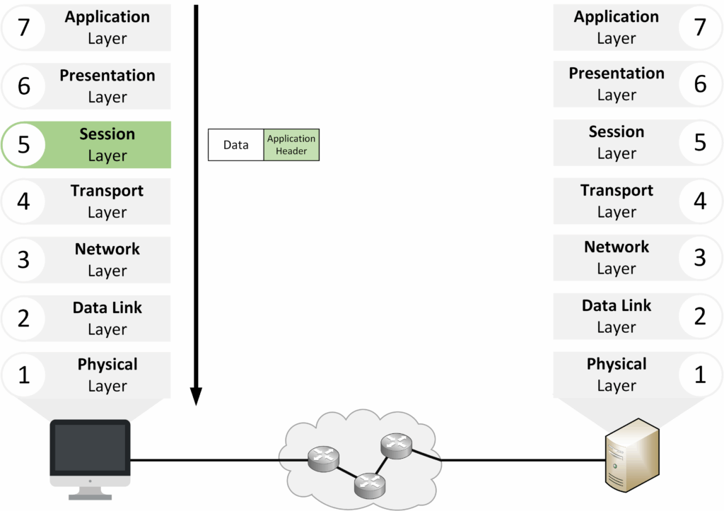
Figure 6 – OSI Layer 5: Session Layer
Key points:
Establishes, maintains, and terminates communication sessions.
Allows many applications to run and communicate at the same time.
Upper Layers Overview
The Upper Layers consist of Layers 7, 6, and 5. They focus on preparing data for transmission.
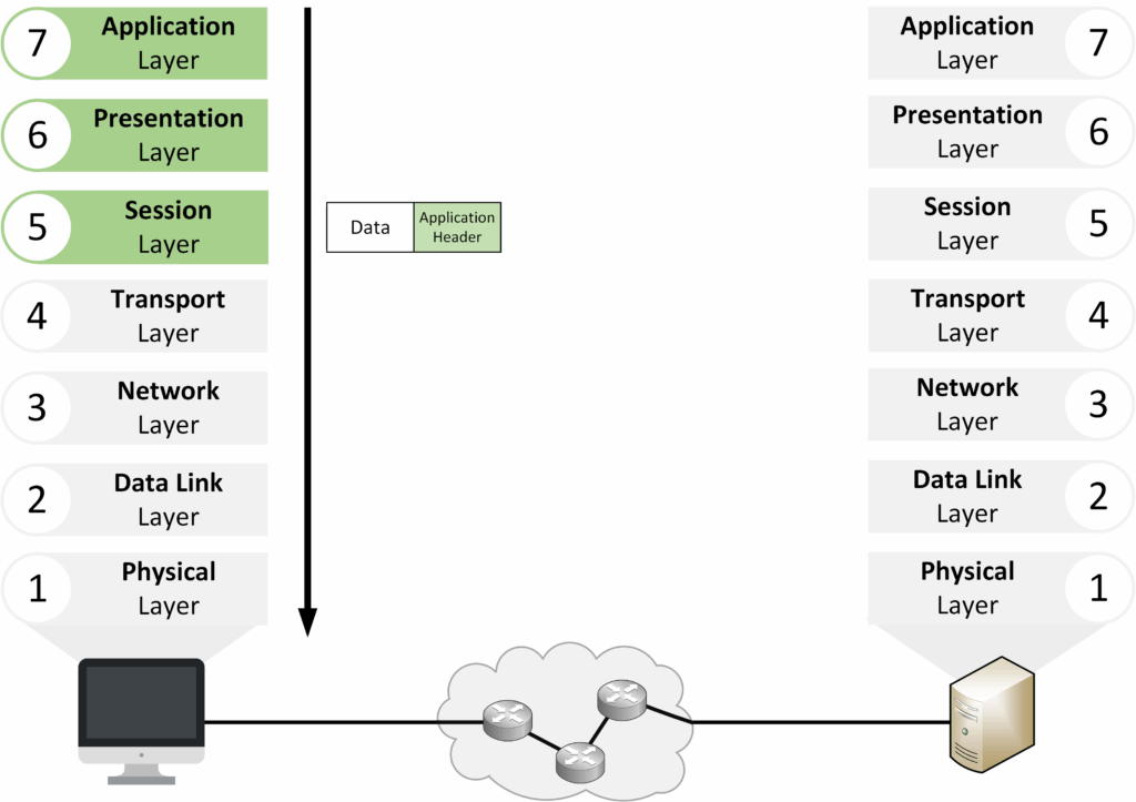
Figure 7 – OSI Upper Layers (Layers 7, 6, 5)
The lower layers (4–1) are responsible for actually delivering the data across the network.
Layer 4 – Transport
The Transport Layer provides end-to-end communication between devices. It splits large streams into smaller segments and uses TCP or UDP to manage delivery.
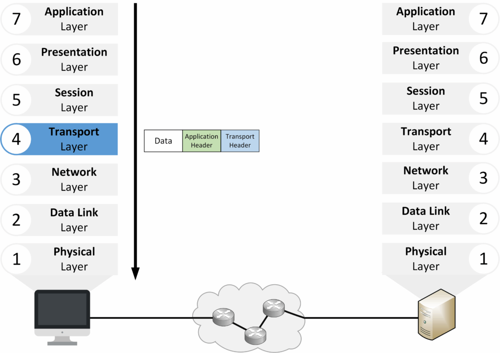
Figure 8 – OSI Layer 4: Transport Layer
Key points:
Segmentation: breaks data into smaller units.
TCP: reliable, ordered delivery.
UDP: faster, connectionless delivery.
Port numbers: identify services (TCP 443 for HTTPS).
Example: When streaming a video, TCP guarantees ordered delivery, while UDP prioritizes speed even if some segments are lost.
Layer 3 – Network
The Network Layer handles logical addressing and routing, ensuring data can move across different networks.
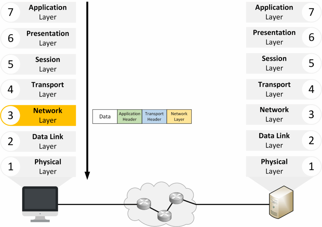
Figure 9 – OSI Layer 3: Network Layer
Key points:
Uses IP addresses to identify source and destination.
Routers operate at this layer.
Creates the packet (segment + IP header).
Analogy: Like a postal service choosing the best route, the Network Layer decides how packets travel through the network.
Layer 2 – Data Link
The Data Link Layer adds framing so data can move reliably across the local network.
It uses MAC addresses to identify devices on the same segment and ensures error detection.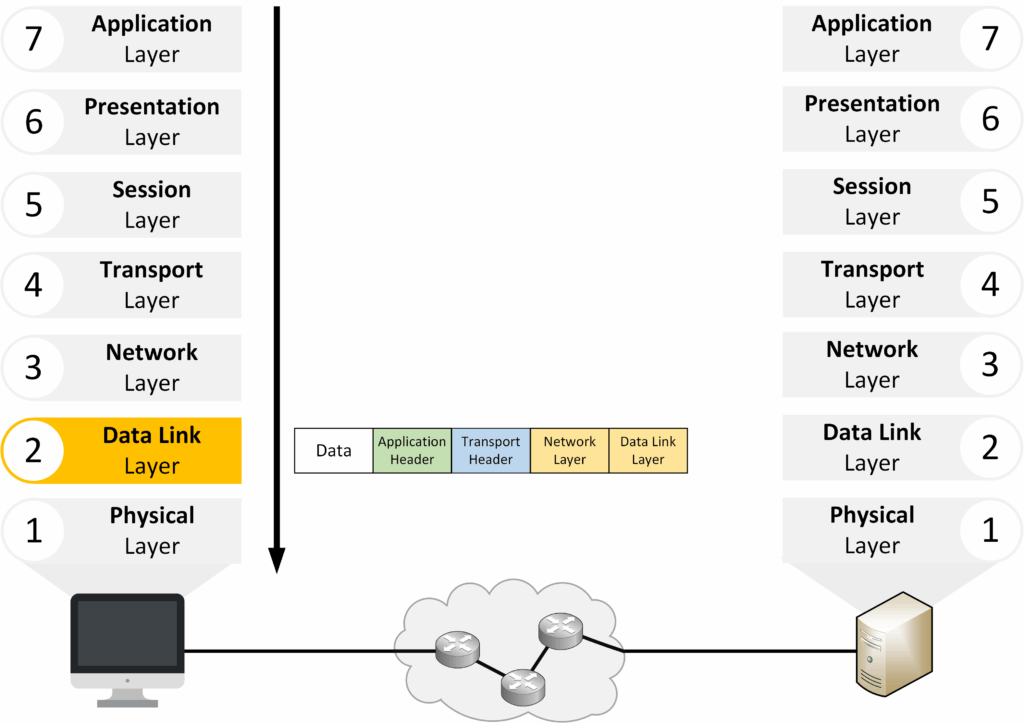
Figure 10 – OSI Layer 2: Data Link Layer
Key points:
Framing: adds a Layer 2 header and trailer to create a frame.
MAC addresses: identify devices within the local network.
Error detection: Frame Check Sequence (FCS).
Switches operate at this layer.
Layer 1 – Physical
The Physical Layer converts frames into electrical, optical, or radio signals and sends them across the transmission medium.
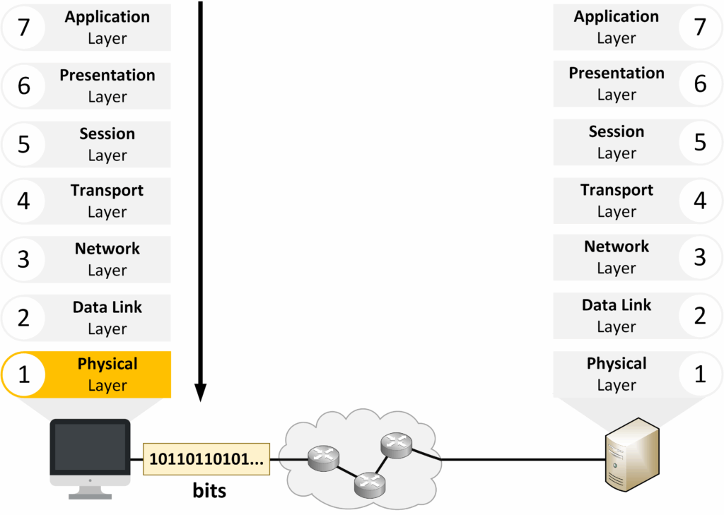
Figure 11 – OSI Layer 1: Physical Layer
Key points:
Defines the physical components: cables, connectors, wireless signals.
Converts frames into bits (1s and 0s) for transmission.
Transmits signals over copper, fiber, or wireless.
Analogy: The Physical Layer is like the road carrying vehicles (frames) to their destination.
De-encapsulation Process
When the receiving device receives the data, it performs decapsulation, which is the reverse of encapsulation.
The data moves up through the OSI layers, with each layer removing the information that its counterpart added on the sender’s side.Layer 1 – Physical
The Physical Layer converts incoming electrical, optical, or radio signals back into raw bits. These bits are then passed to the Data Link Layer.
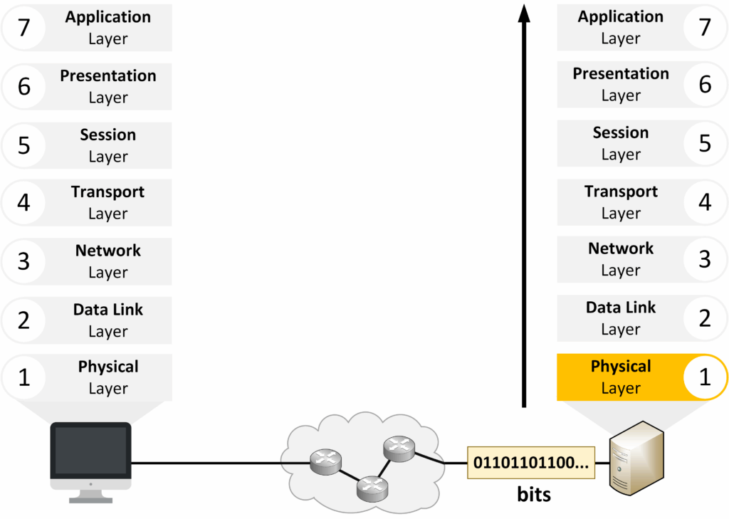
Figure 12 – Start of the De-encapsulation Process
Layer 2 – Data Link
The Data Link Layer groups the bits into a frame, verifies it using the FCS, and removes the Layer 2 header (MAC addresses). It then passes the packet to the Network Layer.
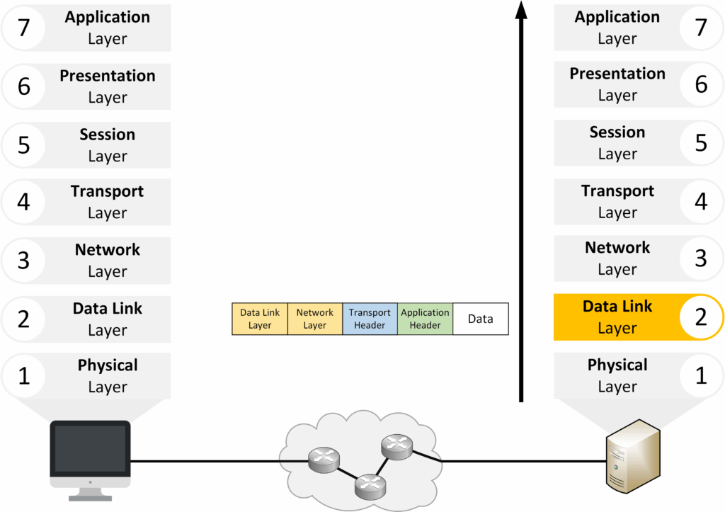
Figure 13 – OSI Layer 2: Data Link Layer in De-encapsulation
Layer 3 – Network
The Network Layer processes the packet, removes the IP header, and checks the source and destination addresses. It forwards the segment to the Transport Layer.
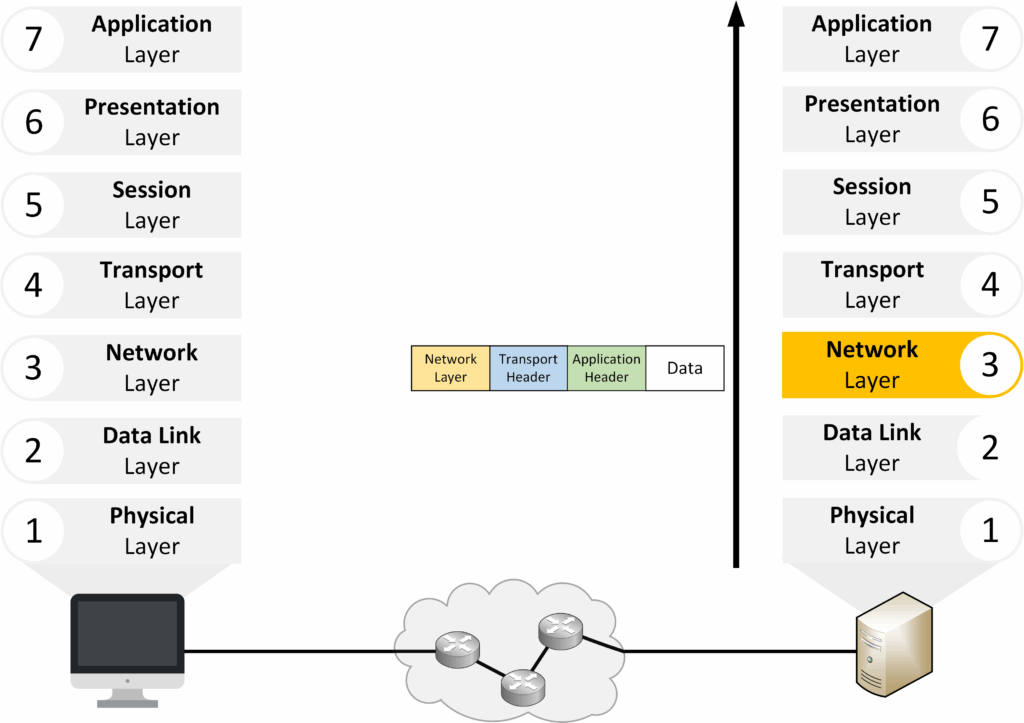
Figure 14 – OSI Layer 3: Network Layer in De-encapsulation
Layer 4 – Transport
The Transport Layer reassembles the segments into the original data stream. It removes the Layer 4 header (port numbers, reliability info) and identifies the correct service.
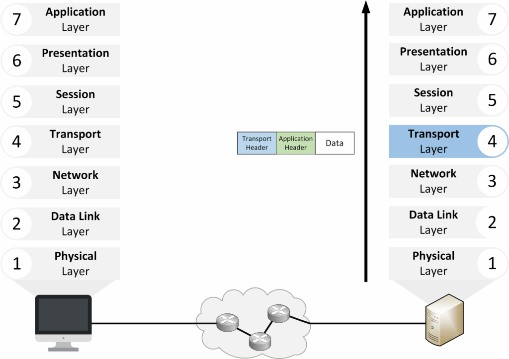
Figure 15 – OSI Layer 4: Transport Layer in De-encapsulation
Layers 5 to 7 – Upper Layers
Once the lower layers finish processing, the data moves into the upper layers of the OSI model: Session, Presentation, and Application. These layers make sure the data is correctly managed, formatted, and delivered to the right application.
Layer 5 – Session
The Session Layer establishes, maintains, and ends the communication session between devices. It keeps track of the session until the transfer is complete.
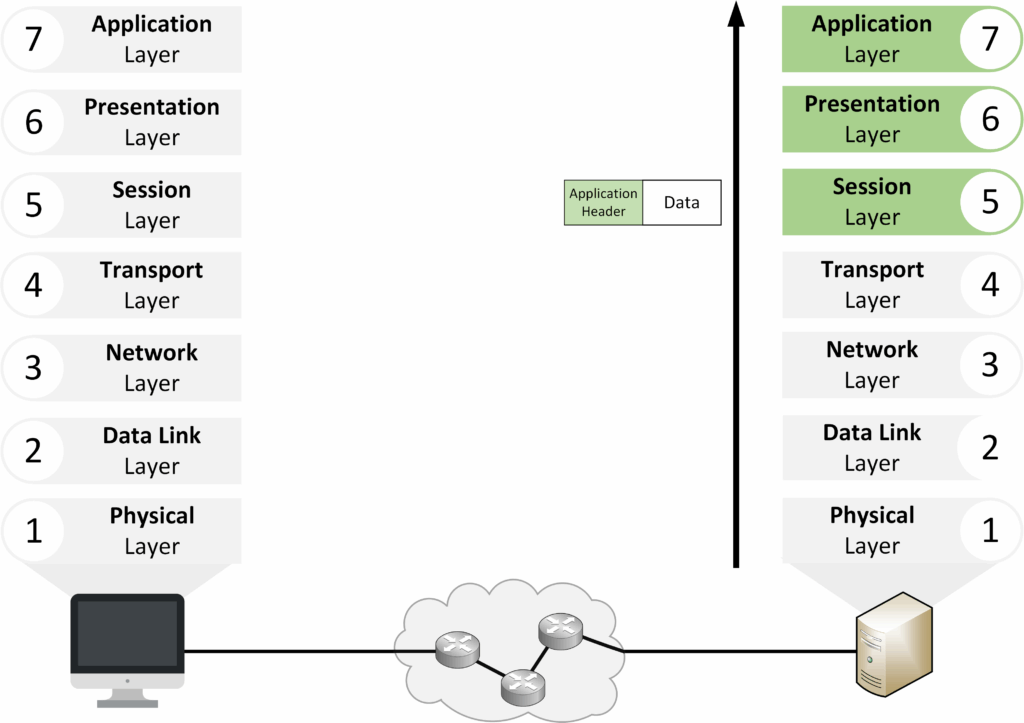
Figure 16 – De-encapsulation in the Upper OSI Layers
Layer 6 – Presentation
The Presentation Layer ensures the data is in a usable format. It may handle translation, compression, or encryption/decryption before passing the data to the application.
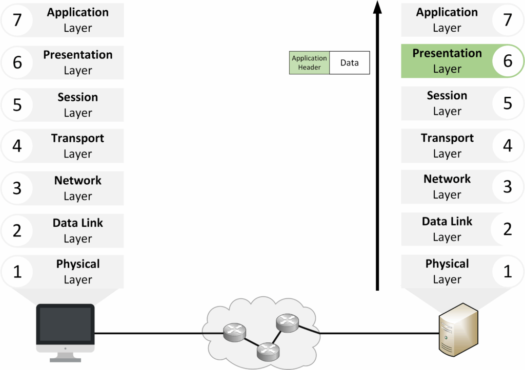
Figure 19 – Decapsulation Presentation Layer
Layer 7 – Application
The Application Layer delivers the final data to the software the user interacts with, such as a browser, email client, or file transfer tool.
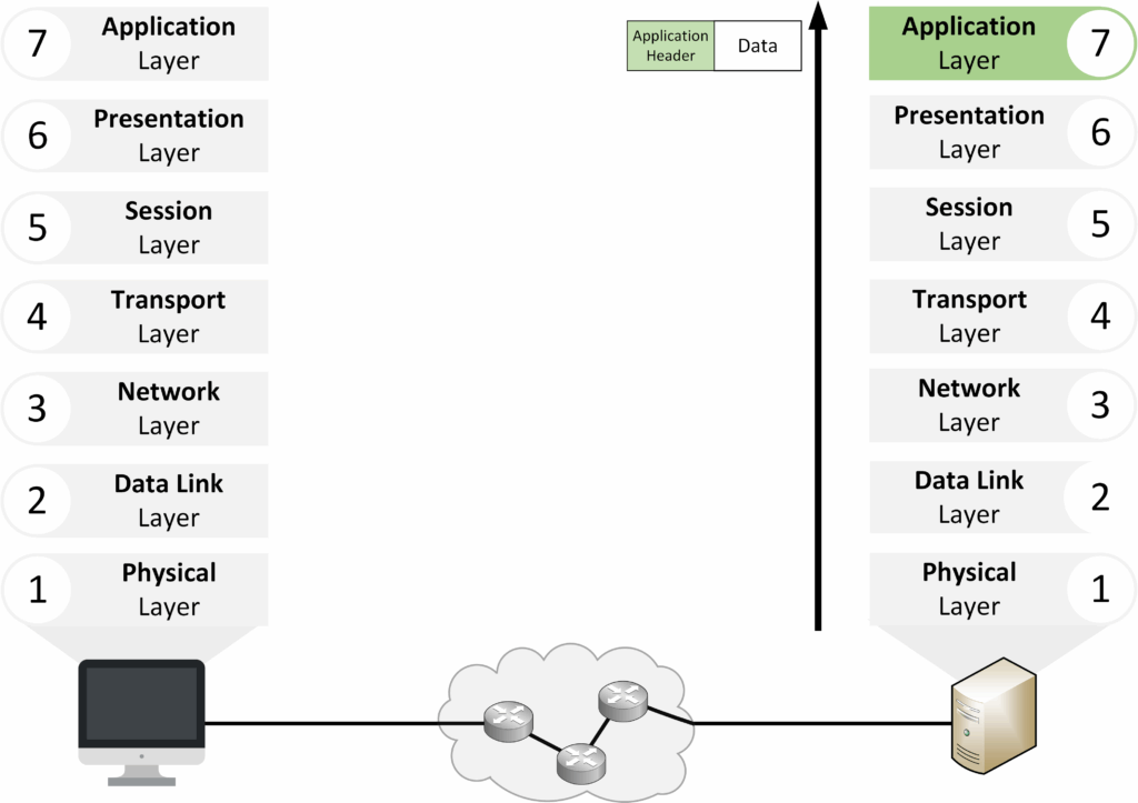
Figure 20 – Decapsulation Application Layer
After understanding encapsulation and decapsulation, the next step is to see how OSI layers interact locally and between devices.
Answer the question below
Which OSI layer uses IP addresses for routing?
The OSI model describes not only the responsibilities of each layer but also how layers interact.
There are two main types of interaction: adjacent-layer and same-layer.Adjacent-layer interaction
This occurs between two layers next to each other on the same device.
Each layer either passes data down to the one below or receives data up from the one above.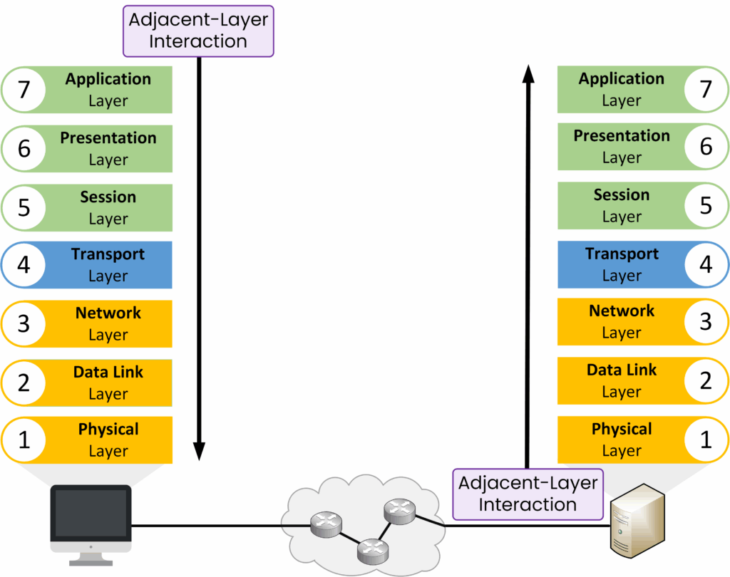
Figure 21 – Adjacent-Layer Interaction in the OSI Model
Example: The Transport Layer sends a segment down to the Network Layer.
Allows the upper layer to rely on the lower layer for specific delivery functions.
Same-layer interaction
This occurs between the same OSI layer on two different devices.
It ensures that both devices understand the data in the same way.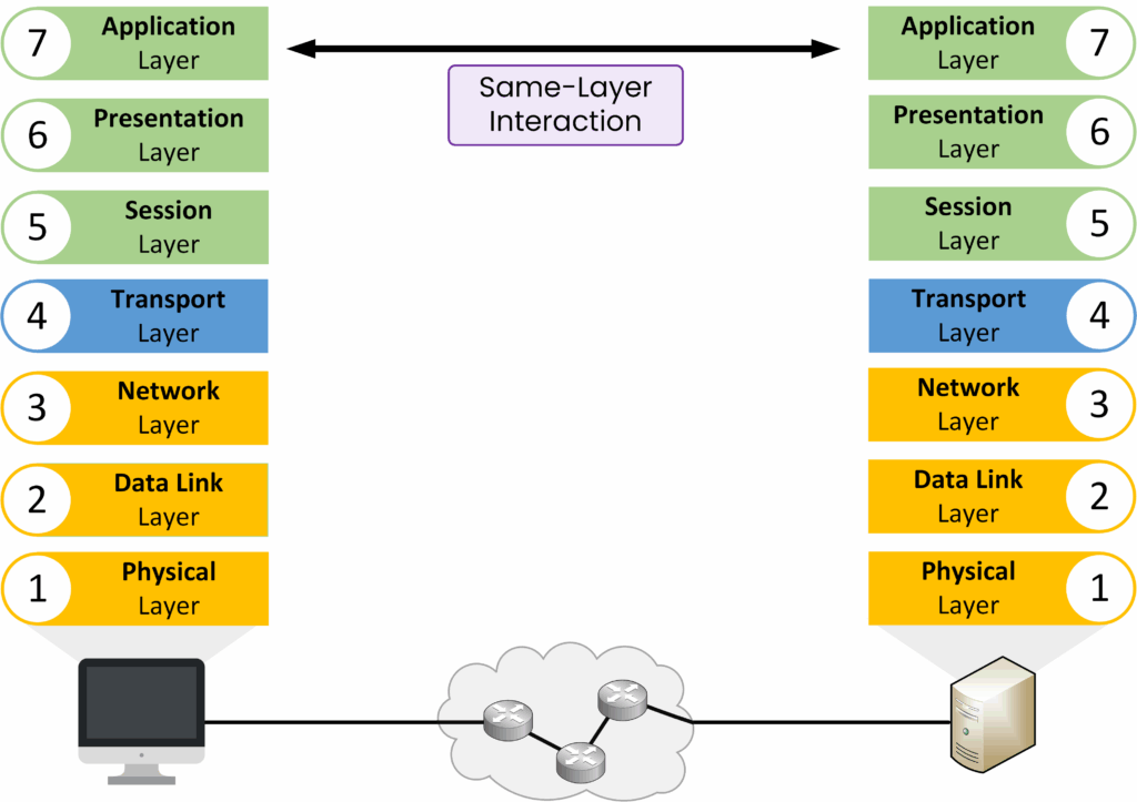
Figure 22 – Same-Layer Interaction in the OSI Model
The Transport Layer on one device talks to the Transport Layer on another device.
Maintaining consistency and compatibility in communication protocols.
Answer the question below
As data moves down the OSI model, each layer adds control information. This produces a specific type of Protocol Data Unit (PDU).
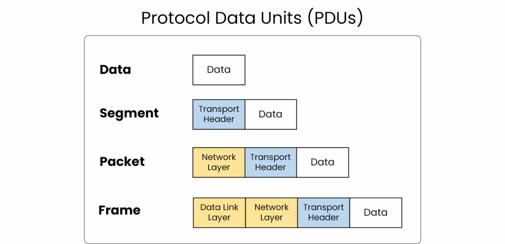
Figure 23 – Protocol Data Units (PDUs) at Different OSI Layers
PDU Types Across OSI Layers
Layer 4 – Transport → Segment (contains port numbers and reliability info, e.g., TCP or UDP).
Layer 3 – Network → Packet (adds source and destination IP addresses for routing).
Layer 2 – Data Link → Frame (adds MAC addresses and error detection with FCS).
Layer 1 – Physical → Bits (1s and 0s transmitted as electrical, optical, or radio signals).
Answer the question below
What is the PDU at Layer 2 of the OSI model?
Memorizing the seven layers of the OSI model can be challenging at first.
Using mnemonics is a simple and effective way to make it easier.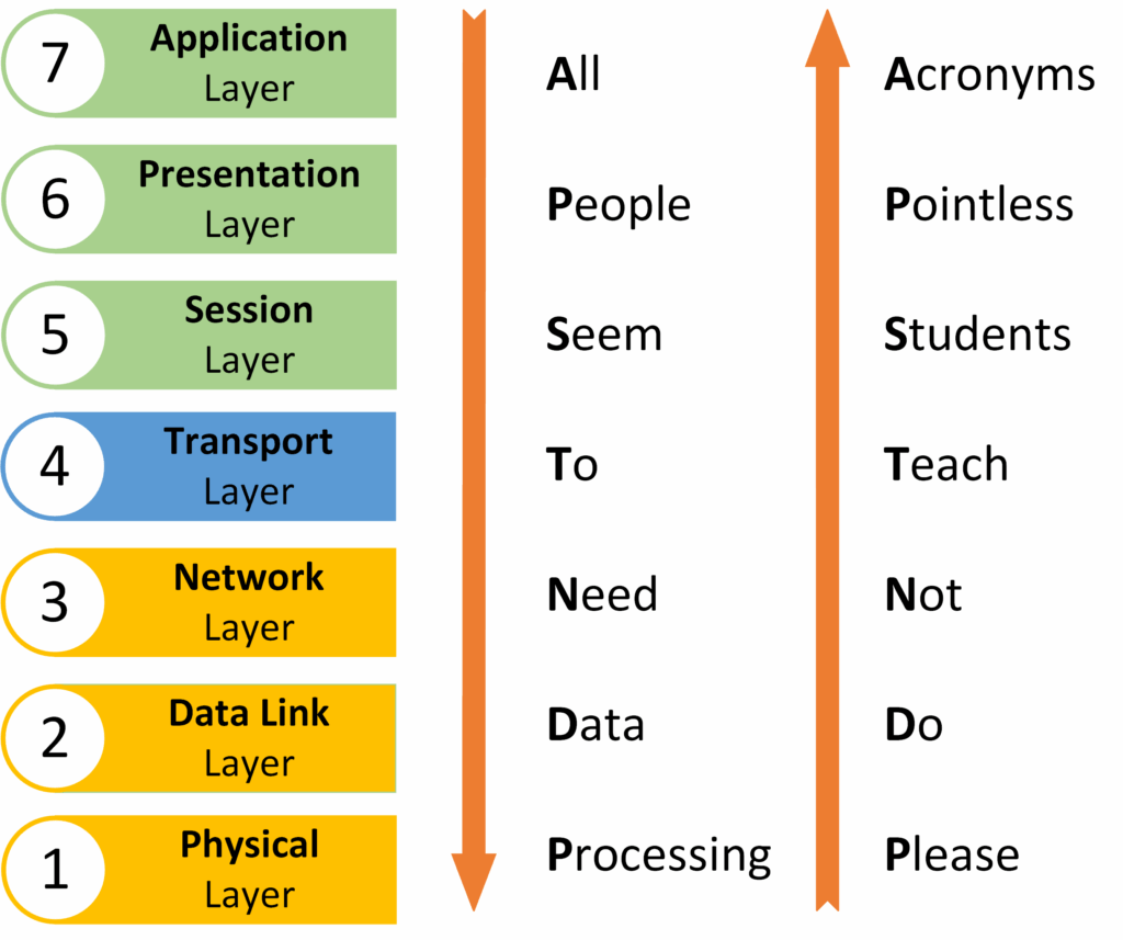
Figure 24 – Mnemonics to Remember the OSI Model Layers
These mnemonics make it easier to recall the OSI layers quickly, whether in exams or while troubleshooting a real network issue.
Now that you can remember all seven OSI layers, let’s step back and see why this model really matters for you as a network engineer.
Answer the question below
The OSI model gives you a clear way to understand how data flows across a network. It also provides a structured method to troubleshoot issues layer by layer, helping you quickly locate and solve problems.
But here’s the key question:
If OSI is just a reference model, which model actually powers the Internet today?
In the next course, we’ll explore the TCP/IP model, the real foundation of modern networking, and see how it works alongside OSI in practice.
Answer the question below
OSI Model
The OSI Model breaks network communication into seven layers, making it easier to understand and troubleshoot. In this lesson, you’ll see how data moves through each layer and why this model still matters today.