To explain Policy-Based Routing (PBR), let’s start from what you already know.
A router normally makes forwarding decisions based on the destination IP address.
It uses the routing table to choose where to send the packet.PBR lets you override that process.
How PBR Works
PBR gives you control over how the router forwards specific traffic.
You match the traffic you care about, then you tell the router where to send it.A PBR policy is built with a route-map.
The route-map decides what traffic to process (MATCH) and what to do with it (SET).
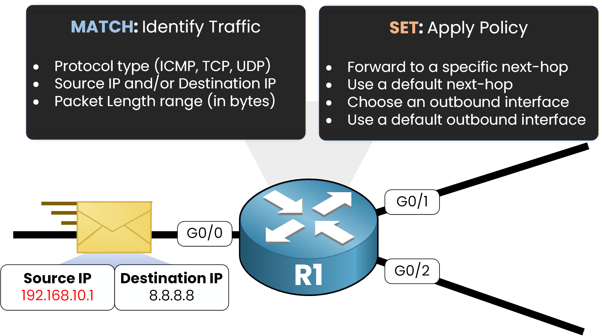
MATCH can identify traffic using different criteria, such as:
IP address (source, destination, or both)
protocol type (ICMP, TCP, UDP)
packet length range (in bytes)
SET defines the forwarding action for matched traffic, for example:
set a specific next-hop
set a default next-hop
set an outbound interface
set a default interface
PBR is evaluated when packets are received on an interface (inbound).
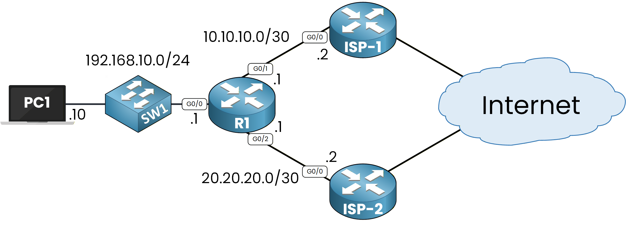
Figure 2 – Policy‑Based Routing Topology
To make this easy to understand, let’s walk through a simple example.
Practical Example
To understand PBR, let’s run a simple example.
Here, PC1 reaches the Internet through R1. R1 is connected to two ISP routers (ISP-1 and ISP-2).
Assume PC1 wants to communicate with 8.8.8.8.We can start with a
pingfrom PC1 to 8.8.8.8 to test traffic:PC1# ping 8.8.8.8 Type escape sequence to abort. Sending 5, 100-byte ICMP Echos to 8.8.8.8, timeout is 2 seconds: !!!!! Success rate is 100 percent (5/5), round-trip min/avg/max = 15/22/38 msThe ping works. Now we want to see the path the traffic takes.
We usetracerouteto display every hop on the way:PC1# traceroute 8.8.8.8 Type escape sequence to abort. Tracing the route to 8.8.8.8 VRF info: (vrf in name/id, vrf out name/id) 1 192.168.10.1 15 msec 11 msec 13 msec 2 10.10.10.2 18 msec 16 msec 17 msec 3 8.8.8.8 25 msec * 32 msecWe can see the first hop is 192.168.10.1, then 10.10.10.2, then 8.8.8.8.
This confirms that R1 forwards traffic through ISP-1, using next-hop 10.10.10.2.As shown in Figure 2, traffic goes through ISP-1 when PBR is not applied.
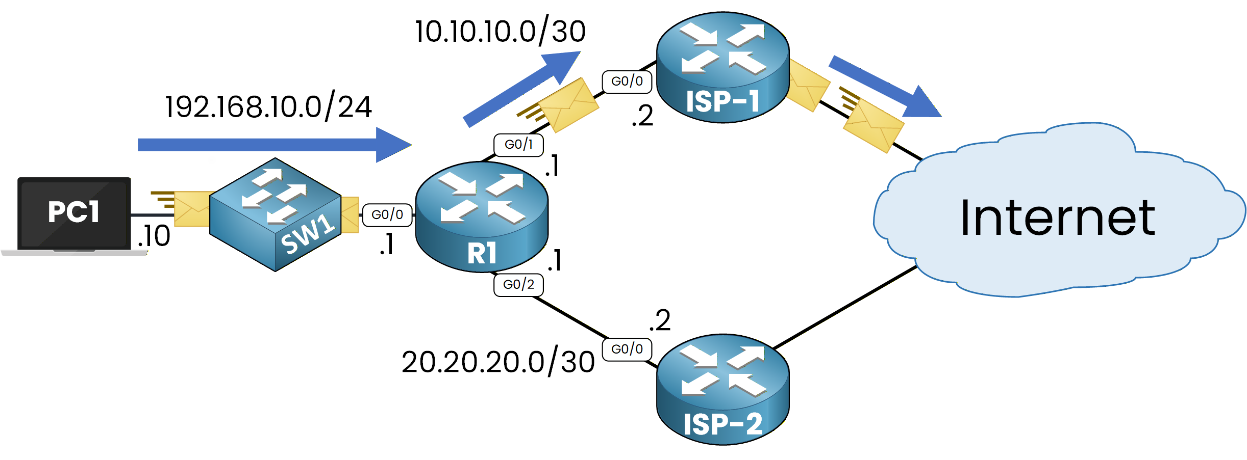
Figure 3 – Traffic Path Without Policy‑Based Routing
Why Traffic Uses ISP-1
On R1, we can check the static route configured to point to ISP-1:
R1# show ip route static
Codes: L - local, C - connected, S - static, R - RIP, M - mobile, B - BGP
       D - EIGRP, EX - EIGRP external, O - OSPF, IA - OSPF inter area
       N1 - OSPF NSSA external type 1, N2 - OSPF NSSA external type 2
       E1 - OSPF external type 1, E2 - OSPF external type 2
       i - IS-IS, su - IS-IS summary, L1 - IS-IS level-1, L2 - IS-IS level-2
       ia - IS-IS inter area, * - candidate default, U - per-user static route
       o - ODR, P - periodic downloaded static route, H - NHRP, l - LISP
       a - application route
       + - replicated route, % - next hop override, p - overrides from PfR

Gateway of last resort is not set

     8.0.0.0/24 is subnetted, 1 subnets
S       8.8.8.0 [1/0] via 10.10.10.2
This shows R1 uses next-hop 10.10.10.2 when the destination is in 8.8.8.0/24.
That explains why traceroute shows the ISP-1 path.Now comes the key point.
PBR allows us to manually influence routing without changing the routing table.On R1, we can apply a policy so that traffic from PC1 goes through ISP-2 instead of ISP-1.
As shown in Figure 3, PBR is applied on R1 on the incoming interface.40 % Complete: you’re making great progress
Ready to pass your CCNP exam?