In the previous lesson, you saw that an ABR generates one Type 3 LSA per network.
OSPF summarization is a powerful feature that allows you to reduce the size of the LSDB and routing tables in a multi-area OSPF design.Let's look at the example below.
Without Summarization
R3 in Area 0 learns four separate inter-area routes coming from Area 1:
10.1.12.0/30
10.1.12.4/30
10.1.12.8/30
10.1.12.12/30
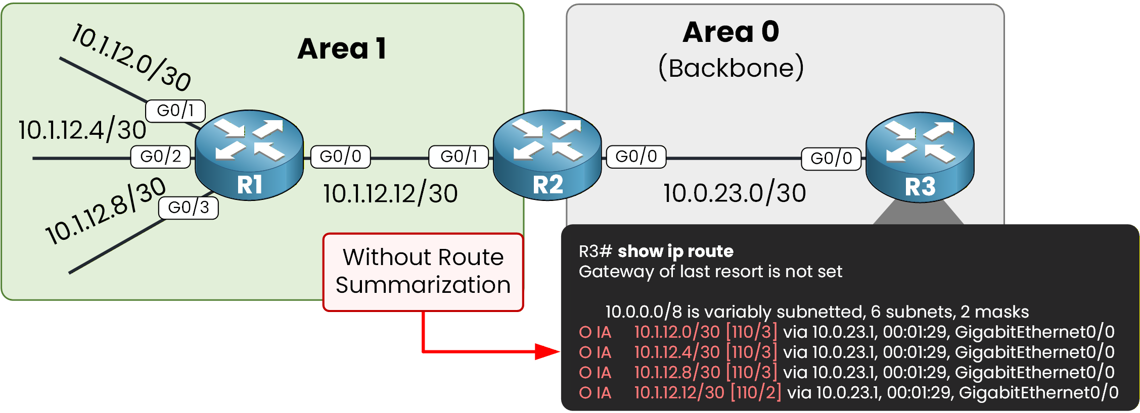
Figure 1 – Without route summarization
From a design perspective, this approach is not very efficient. Even though these are small networks, R3 must maintain four separate Type 3 LSAs in its LSDB and four separate entries in its routing table.
However, if you analyze the addressing scheme carefully, you will notice that these four /30 networks can be summarized into a single prefix: 10.1.12.0/28.
With Summarization Enabled
With summarization enabled on the ABR, R3 no longer learns four individual routes.
Instead, it learns a single summarized inter-area route.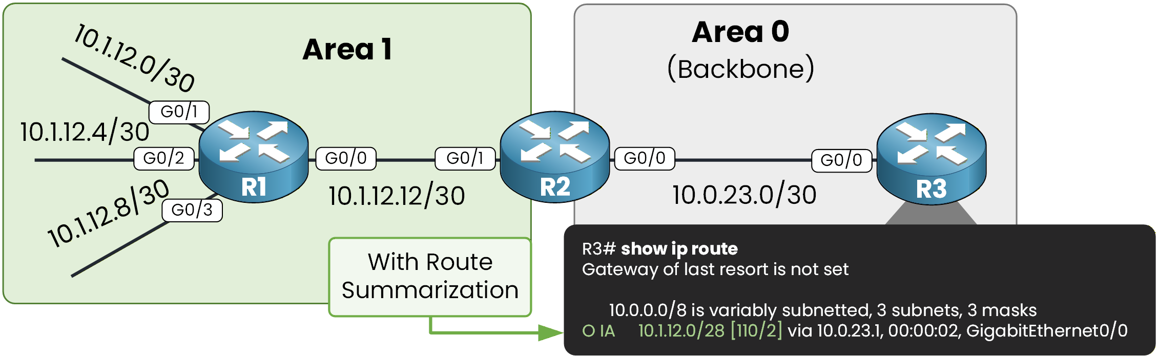
Figure 2 – With route summarization enabled
Inter-area summarization reduces the number of Type 3 LSAs advertised by the ABR into the backbone area.
As a result, routers in other areas maintain a smaller LSDB and a smaller routing table.This improves scalability and reduces SPF processing outside the source area.
Answer the question below
Which type of LSA is reduced when inter-area summarization is enabled?
At this point, all OSPF adjacencies should be established and R3 should learn the four inter-area routes from Area 1.
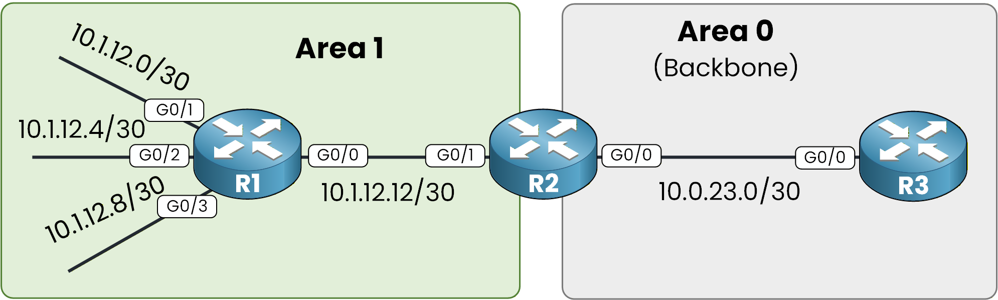
Figure 3 – Basic multi-area topology
R2 is acting as the ABR because it has interfaces in both Area 1 and Area 0.
Step 1 – Configure R1 (Area 1)
We start with R1.
Here, you configure the four /30 interfaces that belong to Area 1 and enable OSPF process 1 to advertise those networks.R1# conf t Enter configuration commands, one per line. End with CNTL/Z. R1(config)# int g0/1 R1(config-if)# ip address 10.1.12.1 255.255.255.252 R1(config-if)# no shut R1(config-if)# exit R1(config)# int g0/2 R1(config-if)# ip address 10.1.12.5 255.255.255.252 R1(config-if)# no shut R1(config-if)# exit R1(config)# int g0/3 R1(config-if)# ip address 10.1.12.9 255.255.255.252 R1(config-if)# no shut R1(config-if)# exit R1(config)# int g0/0 R1(config-if)# ip address 10.1.12.13 255.255.255.252 R1(config-if)# no shut R1(config-if)# exit R1(config)# router ospf 1 R1(config-router)# router-id 1.1.1.1 R1(config-router)# network 10.1.12.0 0.0.0.3 area 1 R1(config-router)# network 10.1.12.4 0.0.0.3 area 1 R1(config-router)# network 10.1.12.8 0.0.0.3 area 1 R1(config-router)# network 10.1.12.12 0.0.0.3 area 1 R1(config-router)# endAt this stage, R1 is fully operating inside Area 1 and generating Type 1 LSAs for its connected networks.
Step 2 – Configure R2 (ABR)
Now move to R2.
R2 is the Area Border Router because it connects Area 1 and Area 0.
It will receive Type 1 LSAs from Area 1 and generate Type 3 LSAs toward the backbone.R2# conf t Enter configuration commands, one per line. End with CNTL/Z. R2(config)# int g0/1 R2(config-if)# ip address 10.1.12.14 255.255.255.252 R2(config-if)# no shut R2(config-if)# exit R2(config)# int g0/0 R2(config-if)# ip address 10.0.23.1 255.255.255.252 R2(config-if)# no shut R2(config-if)# exit R2(config)# router ospf 1 R2(config-router)# router-id 2.2.2.2 R2(config-router)# network 10.1.12.12 0.0.0.3 area 1 R2(config-router)# network 10.0.23.0 0.0.0.3 area 0 R2(config-router)# endOnce configured, R2 translates the Area 1 networks into Type 3 LSAs and advertises them into Area 0.
Step 3 – Configure R3 (Backbone – Area 0)
Finally, configure R3.
R3 belongs only to Area 0. It will receive the inter-area routes generated by the ABR.R3# conf t Enter configuration commands, one per line. End with CNTL/Z. R3(config)# int g0/0 R3(config-if)# ip address 10.0.23.2 255.255.255.252 R3(config-if)# no shut R3(config-if)# exit R3(config)# router ospf 1 R3(config-router)# router-id 3.3.3.3 R3(config-router)# network 10.0.23.0 0.0.0.3 area 0 R3(config-router)# endNow that the OSPF topology is configured, we can focus on configuring OSPF summarization.
Answer the question below
Which router is acting as the Area Border Router in this topology?
OSPF inter-area summarization is configured on the ABR (Area Border Router).
In our topology, R2 is the ABR because it connects Area 1 to Area 0.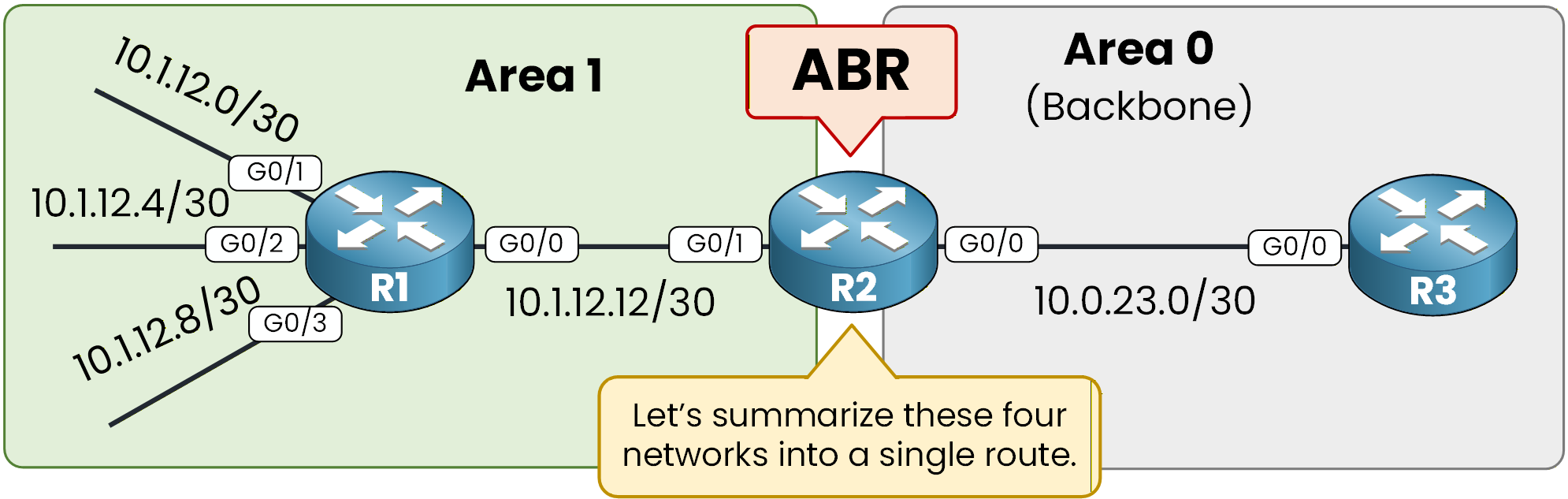
Figure 4 – ABR summarization process
Step 1 – Verify the Current State
Before configuring summarization, verify what R3 currently learns from Area 1.
R3# show ip route ospf
Codes: L - local, C - connected, S - static, R - RIP, M - mobile, B - BGP
       D - EIGRP, EX - EIGRP external, O - OSPF, IA - OSPF inter area
       N1 - OSPF NSSA external type 1, N2 - OSPF NSSA external type 2
       E1 - OSPF external type 1, E2 - OSPF external type 2
       i - IS-IS, su - IS-IS summary, L1 - IS-IS level-1, L2 - IS-IS level-2
       ia - IS-IS inter area, * - candidate default, U - per-user static route
       o - ODR, P - periodic downloaded static route, H - NHRP, l - LISP
       a - application route
       + - replicated route, % - next hop override, p - overrides from PfR

Gateway of last resort is not set

      10.0.0.0/8 is variably subnetted, 6 subnets, 2 masks
O IA     10.1.12.0/30 [110/3] via 10.0.23.1, 00:01:29, GigabitEthernet0/0
O IA     10.1.12.4/30 [110/3] via 10.0.23.1, 00:01:29, GigabitEthernet0/0
O IA     10.1.12.8/30 [110/3] via 10.0.23.1, 00:01:29, GigabitEthernet0/0
O IA     10.1.12.12/30 [110/2] via 10.0.23.1, 00:01:29, GigabitEthernet0/0
You can see four inter-area routes.
Each of these routes corresponds to a separate Type 3 LSA generated by the ABR.Step 2 – Determine the Summary Prefix
Now the question is:
How do you create one network that includes all the smaller networks?
To do this, you must check whether the networks follow each other directly in the IP address space, without gaps between them.Here are the four subnets:
Subnet
Address Range
10.1.12.0/30
10.1.12.0 – 10.1.12.3
10.1.12.4/30
10.1.12.4 – 10.1.12.7
10.1.12.8/30
10.1.12.8 – 10.1.12.11
10.1.12.12/30
10.1.12.12 – 10.1.12.15
If you observe the ranges carefully:
The first network ends at 10.1.12.3
The next one starts immediately at 10.1.12.4
The third starts at 10.1.12.8 right after 10.1.12.7
The fourth starts at 10.1.12.12 right after 10.1.12.11
There are no unused addresses between them. They form one continuous block of addresses:
10.1.12.0 – 10.1.12.15This block contains 16 IP addresses. Since 16 is a power of two (2⁴), it can be represented as a single summarized network:
10.1.12.0/28This /28 prefix includes all four /30 networks exactly, without including unrelated address space.
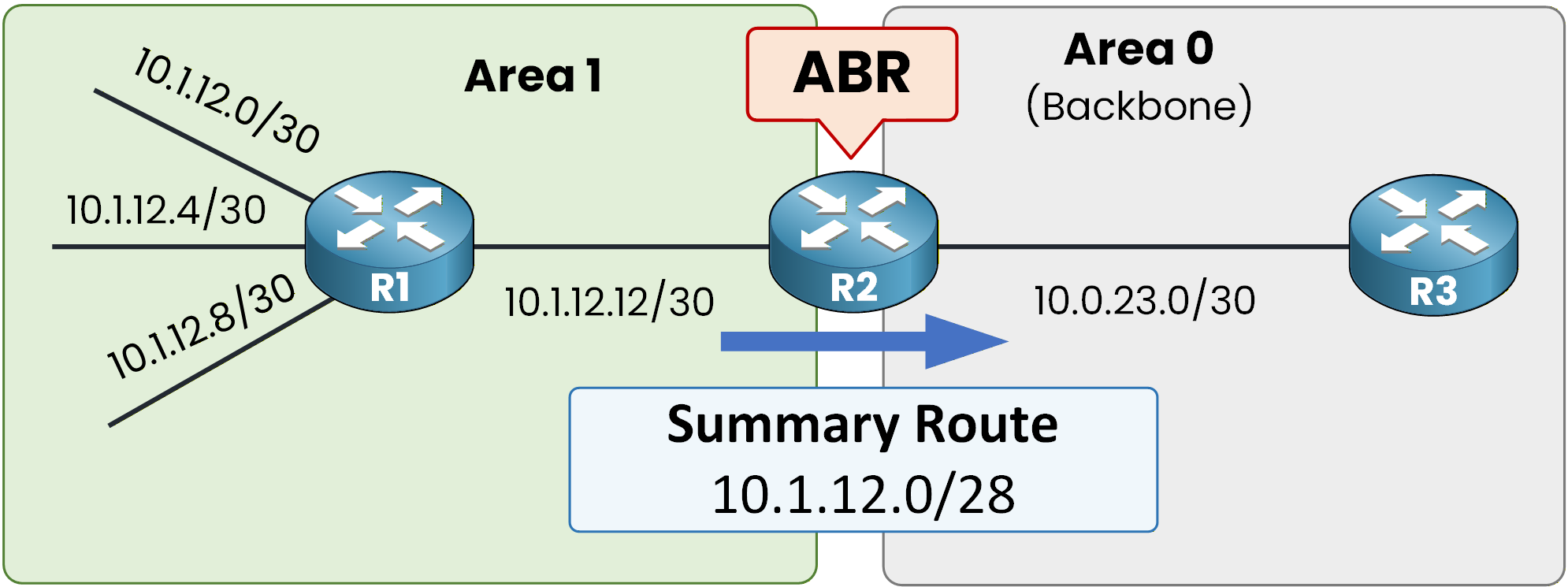
Figure 5 – Generated summary route
Answer the question below
What summarized prefix represents all four /30 networks?
Step 3 – Configure OSPF Summarization on the ABR
You must configure inter-area summarization on the ABR.
In this topology, R2 is the ABR because it connects Area 1 to Area 0.You configure summarization under the OSPF process and specify the source area from which the Type 1 LSAs are learned. In our case, that is Area 1. You also define the summary range that you want to advertise.
R2# conf t
Enter configuration commands, one per line.  End with CNTL/Z.
R2(config)# router ospf 1
R2(config-router)# area 1 range 10.1.12.0 255.255.255.240
R2(config-router)# end
This command tells R2 that when it receives Type 1 LSAs from Area 1 that fall within the 10.1.12.0/28 range, it should generate a single Type 3 LSA for the summary prefix and suppress the more specific Type 3 LSAs toward other areas.
After configuring this, you can verify directly on the ABR:
R2# show ip route ospf
Codes: L - local, C - connected, S - static, R - RIP, M - mobile, B - BGP
       D - EIGRP, EX - EIGRP external, O - OSPF, IA - OSPF inter area
       N1 - OSPF NSSA external type 1, N2 - OSPF NSSA external type 2
       E1 - OSPF external type 1, E2 - OSPF external type 2
       i - IS-IS, su - IS-IS summary, L1 - IS-IS level-1, L2 - IS-IS level-2
       ia - IS-IS inter area, * - candidate default, U - per-user static route
       o - ODR, P - periodic downloaded static route, H - NHRP, l - LISP
       a - application route
       + - replicated route, % - next hop override, p - overrides from PfR

Gateway of last resort is not set

      10.0.0.0/8 is variably subnetted, 8 subnets, 3 masks
O        10.1.12.0/28 is a summary, 00:00:46, Null0
O        10.1.12.0/30 [110/2] via 10.1.12.13, 00:00:46, GigabitEthernet0/1
O        10.1.12.4/30 [110/2] via 10.1.12.13, 00:00:46, GigabitEthernet0/1
O        10.1.12.8/30 [110/2] via 10.1.12.13, 00:00:46, GigabitEthernet0/1
You still see the individual /30 routes in Area 1, but now a summary route to Null0 is also installed.
You may wonder why the summary route points to Null0.
The ABR automatically installs a discard route (Null0) for the summary prefix. This is a loop-prevention mechanism. If a more specific subnet within the summary range is missing from the routing table, traffic matching only the summary will be dropped instead of being forwarded incorrectly.
Answer the question below
To which interface is the summary route installed on the ABR?
Step 4 – Understand the OSPF Behavior Behind the Scenes
If you look at how OSPF operates internally, the behavior is straightforward.
R2 acting as the ABR receives Type 1 LSAs from Area 1.
Each Type 1 LSA describes a specific intra-area network (in our case, the four /30 networks).
Under normal conditions, the ABR would generate one Type 3 LSA per network and advertise each of them into Area 0.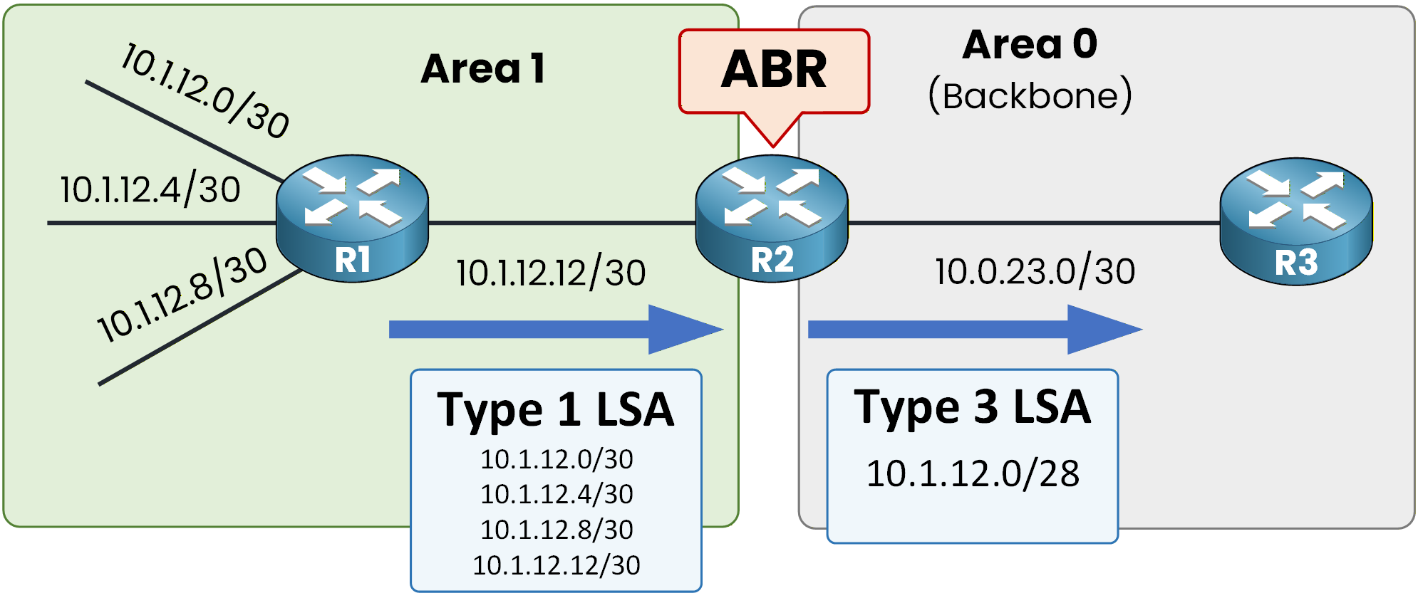
Figure 6 – Type 1 to Type 3 summarization
With inter-area summarization configured, the process changes slightly.
R2 still receives the same Type 1 LSAs from Area 1 and still runs the SPF calculation for that area.
However, instead of generating four separate Type 3 LSAs toward Area 0, the ABR generates a single Type 3 LSA for the summary prefix 10.1.12.0/28.
The more specific Type 3 LSAs are suppressed and are not advertised into the backbone.
From Area 0's perspective, only the summarized network exists.Answer the question below
After summarization is configured, how many Type 3 LSAs are generated toward Area 0?
Step 5 – Verify the Result on R3
You can verify this on R3:
R3# show ip route ospf
Codes: L - local, C - connected, S - static, R - RIP, M - mobile, B - BGP
       D - EIGRP, EX - EIGRP external, O - OSPF, IA - OSPF inter area
       N1 - OSPF NSSA external type 1, N2 - OSPF NSSA external type 2
       E1 - OSPF external type 1, E2 - OSPF external type 2
       i - IS-IS, su - IS-IS summary, L1 - IS-IS level-1, L2 - IS-IS level-2
       ia - IS-IS inter area, * - candidate default, U - per-user static route
       o - ODR, P - periodic downloaded static route, H - NHRP, l - LISP
       a - application route
       + - replicated route, % - next hop override, p - overrides from PfR

Gateway of last resort is not set

      10.0.0.0/8 is variably subnetted, 3 subnets, 3 masks
O IA     10.1.12.0/28 [110/2] via 10.0.23.1, 00:00:02, GigabitEthernet0/0
R3 now has a single inter-area (O IA) route representing the summarized prefix.
The detailed /30 routes still exist inside Area 1 and in the ABR's LSDB for Area 1, but they are no longer advertised individually into Area 0. This is the key effect of inter-area summarization: fewer Type 3 LSAs in other areas, smaller LSDBs, and simplified routing tables.
Answer the question below
What is the summarized prefix learned by R3 after inter-area summarization?
One important feature of OSPF inter-area summarization is that you can manually set the metric of the summary route.
By default, the ABR uses the lowest metric among the component routes inside the summary range. However, you can override this behavior and assign a specific cost to the summary LSA. This is useful when you want to influence path selection.

Figure 7 - OSPF Summarization with Modified Cost
Setting a Custom Metric on the Summary Route
In this example, we configure the summary route with a metric of 10 on the ABR (R2).
To do this, you simply add thecostkeyword at the end of the area range command:R2# conf t Enter configuration commands, one per line. End with CNTL/Z. R2(config)# router ospf 1 R2(config-router)# area 1 range 10.1.12.0 255.255.255.240 cost 10 R2(config-router)# endThis command forces the ABR to advertise the Type 3 summary LSA with a metric of 10.
Now verify on R3:R3# show ip route ospf Codes: L - local, C - connected, S - static, R - RIP, M - mobile, B - BGP D - EIGRP, EX - EIGRP external, O - OSPF, IA - OSPF inter area N1 - OSPF NSSA external type 1, N2 - OSPF NSSA external type 2 E1 - OSPF external type 1, E2 - OSPF external type 2 i - IS-IS, su - IS-IS summary, L1 - IS-IS level-1, L2 - IS-IS level-2 ia - IS-IS inter area, * - candidate default, U - per-user static route o - ODR, P - periodic downloaded static route, H - NHRP, l - LISP a - application route + - replicated route, % - next hop override, p - overrides from PfR Gateway of last resort is not set 10.0.0.0/8 is variably subnetted, 3 subnets, 3 masks O IA 10.1.12.0/28 [110/11] via 10.0.23.1, 00:00:16, GigabitEthernet0/0As you can see, the route on R3 has a metric of 11.
The summary LSA sent by R2 carries a metric of 10.
R3 adds the outgoing interface cost (1) to reach R2.10 + 1 = 11
That is why the final OSPF metric on R3 is 11.
You can confirm the metric inside the Type 3 LSA:R3# show ip ospf database summary OSPF Router with ID (3.3.3.3) (Process ID 1) Summary Net Link States (Area 0) LS age: 491 Options: (No TOS-capability, DC, Upward) LS Type: Summary Links(Network) Link State ID: 10.1.12.0 (summary Network Number) Advertising Router: 2.2.2.2 LS Seq Number: 80000003 Checksum: 0x40E0 Length: 28 Network Mask: /28 MTID: 0 Metric: 10It shows a metric of 10, which matches the value configured on the ABR.
Answer the question below
What metric value is carried inside the Type 3 summary LSA?