Wait.
In the previous lesson, you configured a multi-area OSPF network without even knowing what an area is.
Let's fix that.OSPF works very well in a single-area design.
But imagine this:
What happens if you place many routers inside Area 0 (the backbone)?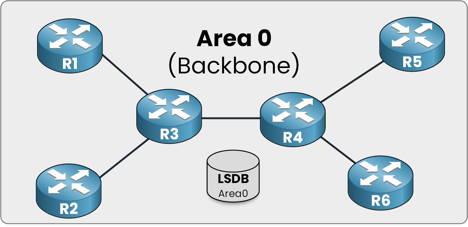
Figure 1 - Area 0 LSDB overview
Scalability issues start to appear.
Let's understand why.In the example above, you can see six routers inside Area 0.
Shared LSDB in Area 0
All of them are backbone routers.
And they all share the same Link-State Database (LSDB).This means every router stores the same topology information.
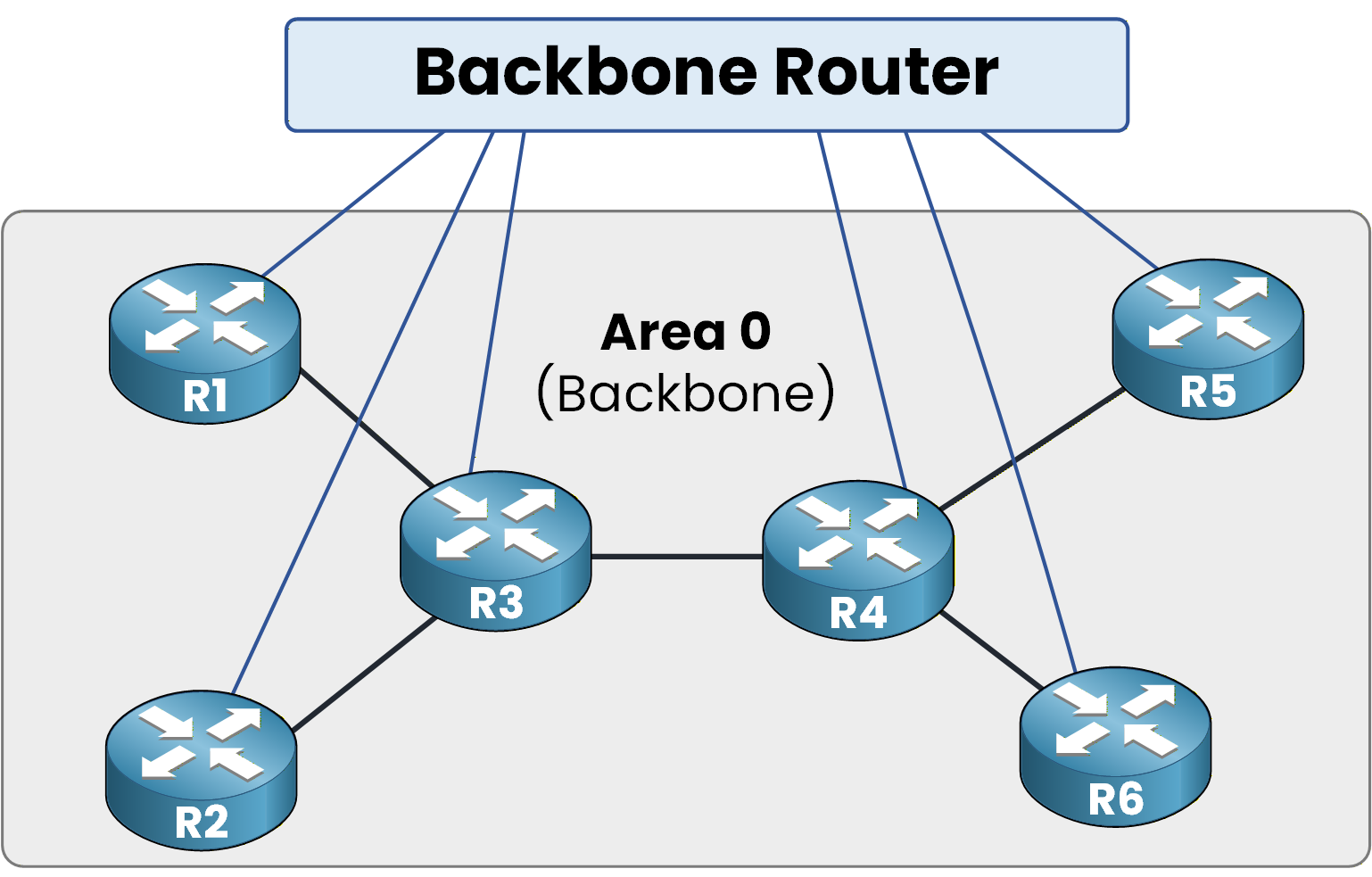
Figure 2 - Backbone router role
Now think about it:
The more routers you add, the bigger the LSDB becomes.Answer the question below
If you add many routers inside Area 0, what becomes larger?
What Happens During a Topology Change?
If we follow the OSPF concept strictly, you already know that when a topology change occurs,
LSAs are distributed inside Area 0 so that all routers are informed about the change.That is exactly what is happening below.
R5 experiences a link failure, and this triggers an OSPF reaction.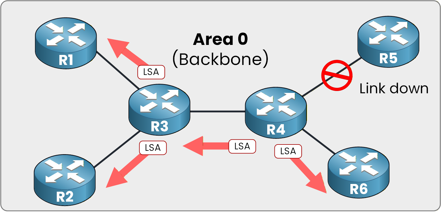
Figure 3 - Global LSA flooding
LSAs are sent across the topology to indicate the change.
All routers inside Area 0 take this new information into account, and the SPF algorithm is executed on every router.The Scalability Problem
If all routers must execute SPF every time a small change happens in Area 0, CPU usage increases significantly.
The more routers you have in Area 0, the greater the impact.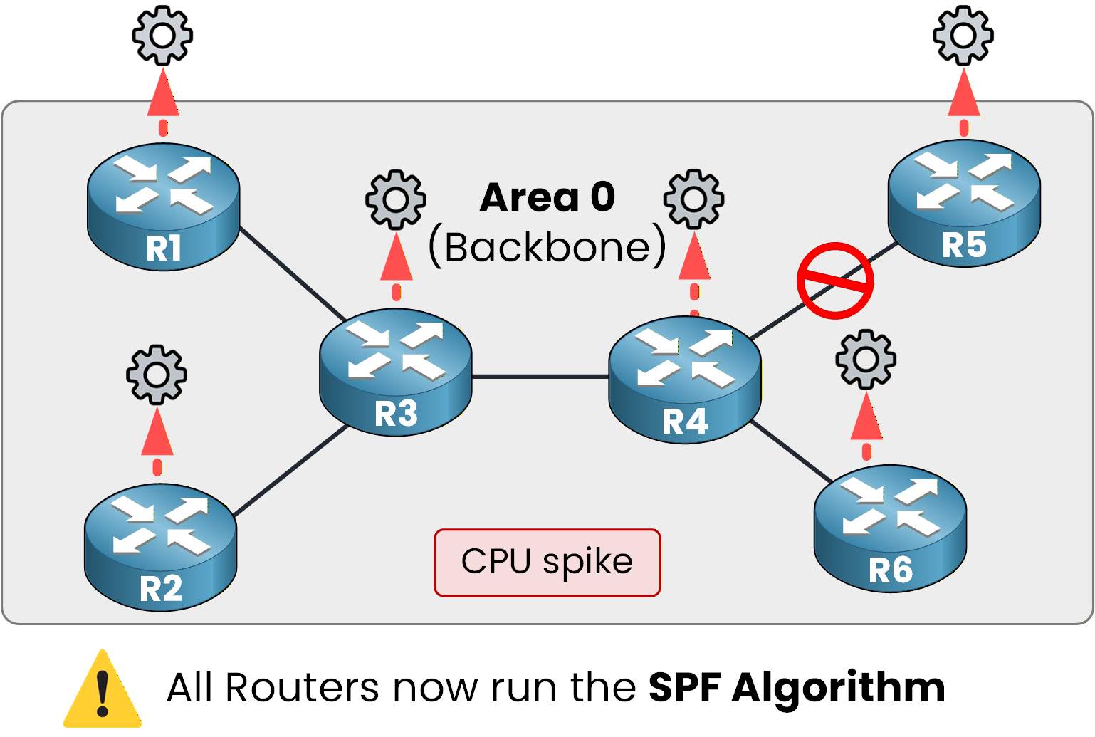
Figure 4 - Full SPF recalculation
The size of the LSDB increases with the number of routers.
It is clear that single-area OSPF does not scale well when there are many routers.This is where OSPF areas come into play.
Answer the question below
When a topology change occurs, which algorithm is executed on every router?
OSPF Multi-Area allows you to divide OSPF into multiple areas.
As you can see below, each area has its own dedicated LSDB.Area Separation and Independent LSDBs
Each router runs a separate SPF calculation for every area in which it has interfaces.
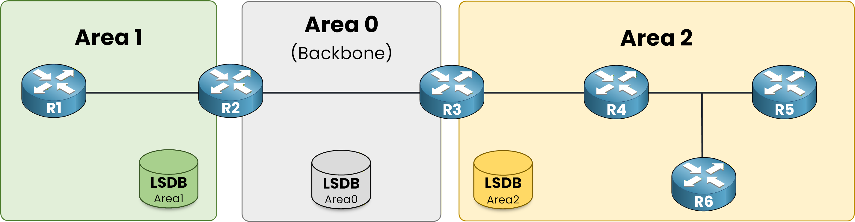
Figure 5 - Separate LSDB per area
A topology change in Area 2 no longer forces the routers of Area 1 to run SPF.
There is one fundamental rule you must understand.
Area 0 is the central backbone area, and all inter-area traffic must transit through Area 0.
All other areas must connect directly to Area 0 for Multi-Area OSPF to function properly.Answer the question below
Which area is the central backbone area in OSPF Multi-Area?
The Role of the ABR
To achieve this, OSPF uses a router called an Area Border Router (ABR).
As you can see below, an ABR connects two areas together.
An ABR maintains one LSDB per area.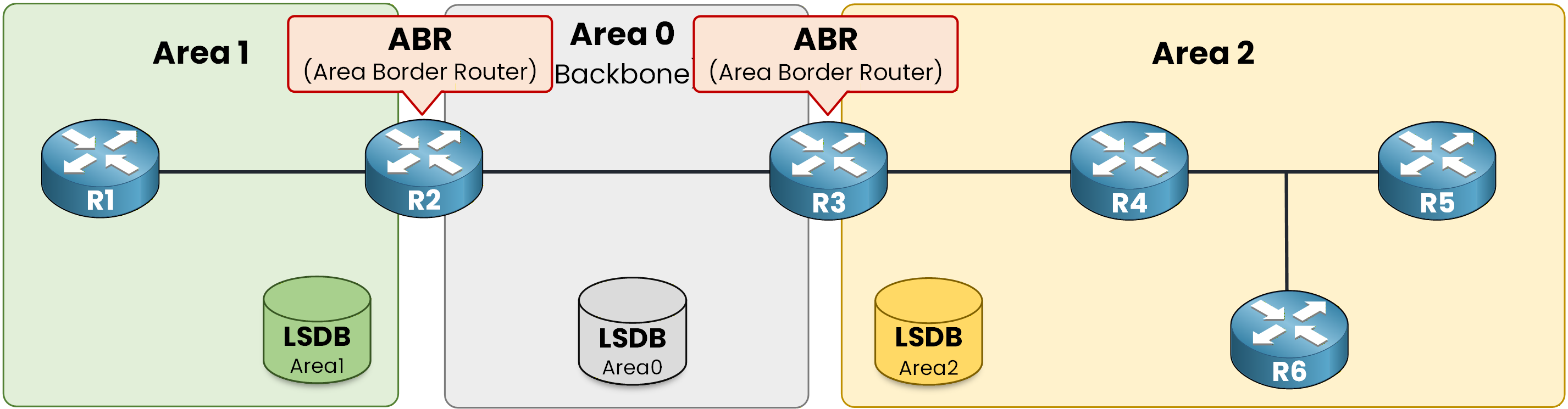
Figure 6 - ABR multi-area design
Look at this topology again: R2 and R3 are the two routers you configured in the previous course.
R2 is an ABR connecting Area 1 and Area 0. R3 is an ABR connecting Area 0 and Area 2.Answer the question below
What is the acronym for the router that connects two areas together?
Connect to R2 and verify it.
R2# show ip ospf
 Routing Process "ospf 1" with ID 2.2.2.2
 Start time: 00:01:32.044, Time elapsed: 01:12:54.392
 Supports only single TOS(TOS0) routes
 It is an area border router
 Number of areas in this router is 2. 2 normal 0 stub 0 nssa
The output confirms it: R2 is an area border router, with one LSDB per area.
What O IA Means
Now, the O IA routes from the previous course.
Connect to R1, inside Area 1, and look at its routing table.R1# show ip route ospf Codes: O - OSPF, IA - OSPF inter area E1 - OSPF external type 1, E2 - OSPF external type 2 Gateway of last resort is not set 10.0.0.0/8 is variably subnetted, 5 subnets, 3 masks O IA 10.0.23.0/30 [110/2] via 10.1.12.2, 01:28:14, GigabitEthernet0/0 O IA 10.2.34.0/30 [110/3] via 10.1.12.2, 01:27:04, GigabitEthernet0/0 O IA 10.2.100.0/24 [110/4] via 10.1.12.2, 00:17:39, GigabitEthernet0/0IA means Inter-Area.
These networks are not in Area 1. R1 learned them from another area, through the ABR.Answer the question below
A route marked O IA was learned from another ___.