Imagine you are the network engineer responsible for connecting the headquarters in New York with the branch office in San Francisco.
Your goal is simple: allow the two sites to communicate with each other.The Connectivity Problem
As shown in the diagram, both sites connect to the Internet through two ISP routers.
Traffic between the two networks must travel through the ISP infrastructure.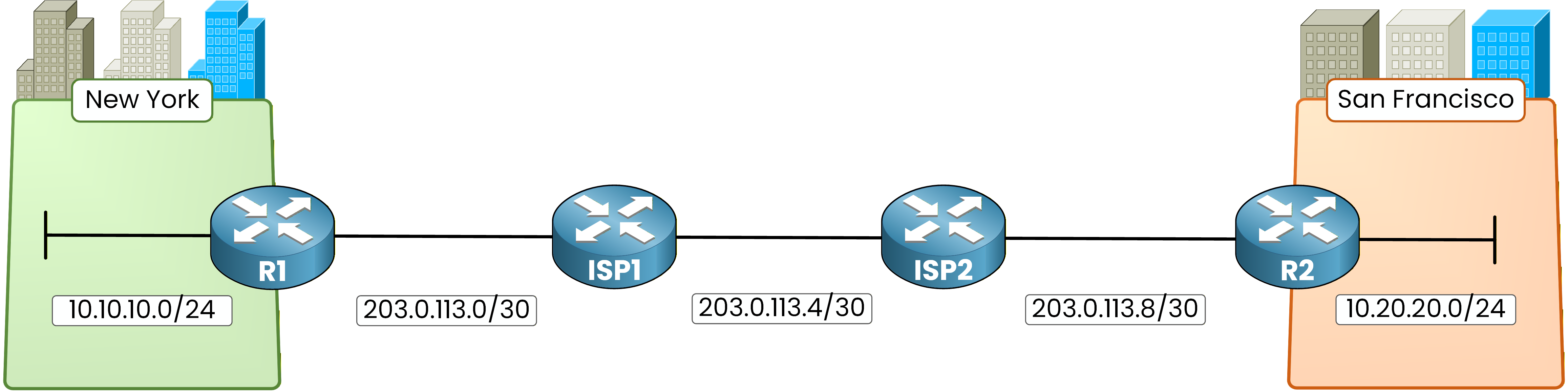
Figure 1 - Enterprise sites network topology
But there is a problem.
The ISP routers do not know your internal networks and they are not part of your enterprise routing design.
As a result, even though both sites can reach the Internet, the two LANs are not logically connected.Underlay
To solve this problem, network designs are often described using two layers: the underlay and the overlay.
The underlay is the physical infrastructure that carries packets across the network.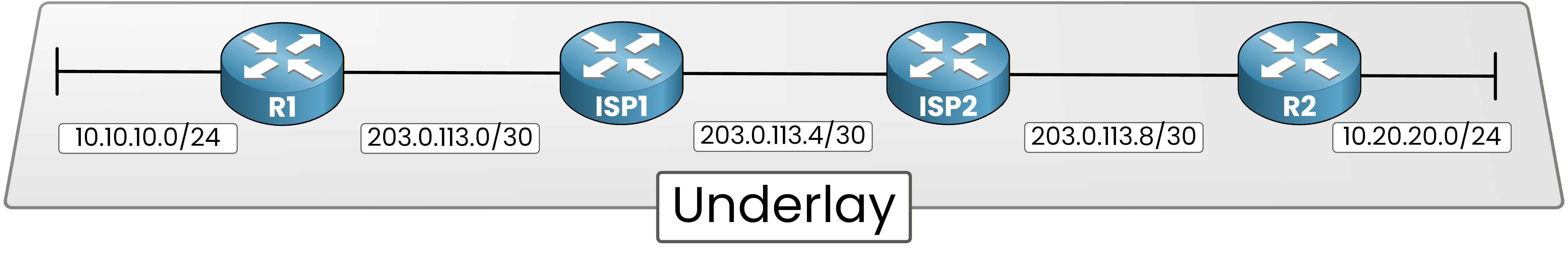
Figure 2 - GRE underlay network
In this example, the underlay is simply the Internet and the ISP routers.
When R1 sends traffic, packets travel through ISP1 and ISP2 before reaching R2.
The underlay transports packets, but it does not create a logical connection between the two sites.Overlay
The overlay is a logical network built on top of the underlay.
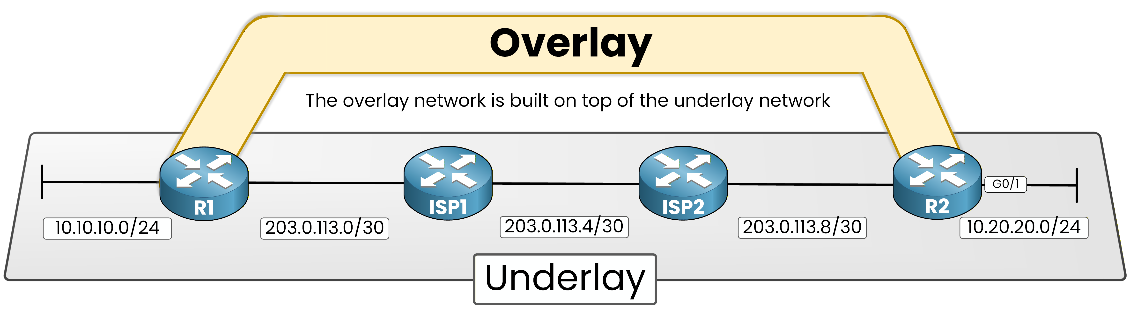
Figure 3 - Overlay network concept
Even though packets still travel through the ISP routers, the overlay allows R1 and R2 to appear directly connected.
From the router’s perspective, the two sites now communicate through a virtual connection built above the physical infrastructure.Answer the question below
What is the name of the physical network that transports packets between routers?
GRE Tunnel
To build this overlay network, we use GRE (Generic Routing Encapsulation).
GRE creates a tunnel between two routers across another network.GRE encapsulates packets using IP protocol number 47, which allows routers to transport different Layer-3 protocols across an IP network.
In this example, the tunnel is created between R1 and R2.
R1 is the tunnel source
R2 is the tunnel destination
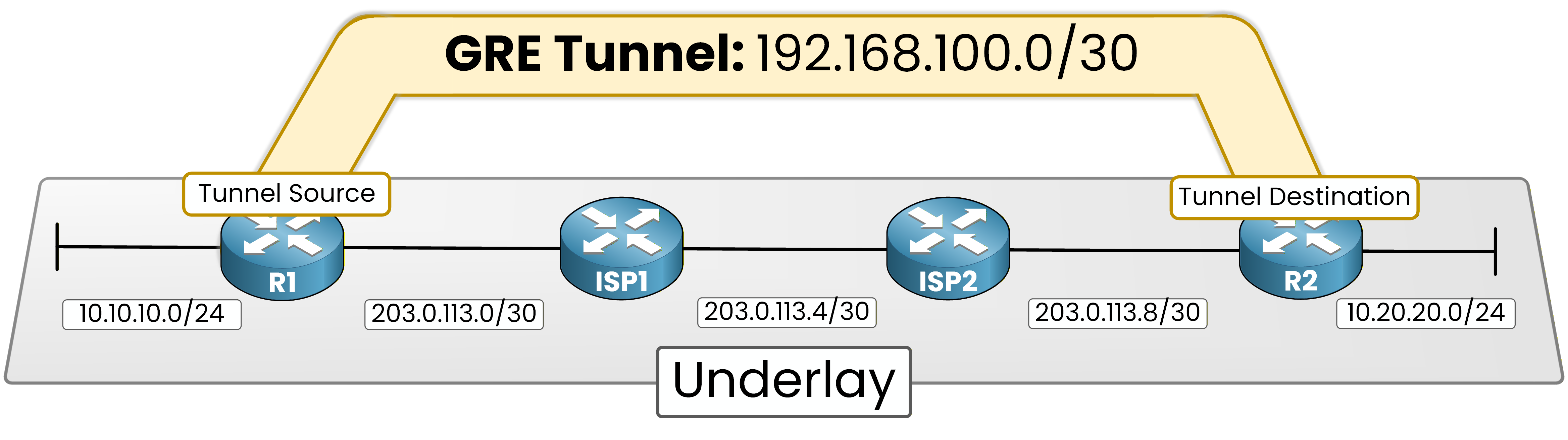
Figure 4 - GRE tunnel endpoints
The Internet acts as the underlay network.
However, the routers communicate through a tunnel interface, which creates a logical link between them.From the router’s perspective, the tunnel behaves like a direct link.
This is what allows the overlay to exist on top of the physical infrastructure.How GRE works
You might now wonder how traffic actually travels through the tunnel.
GRE works by using a process called encapsulation.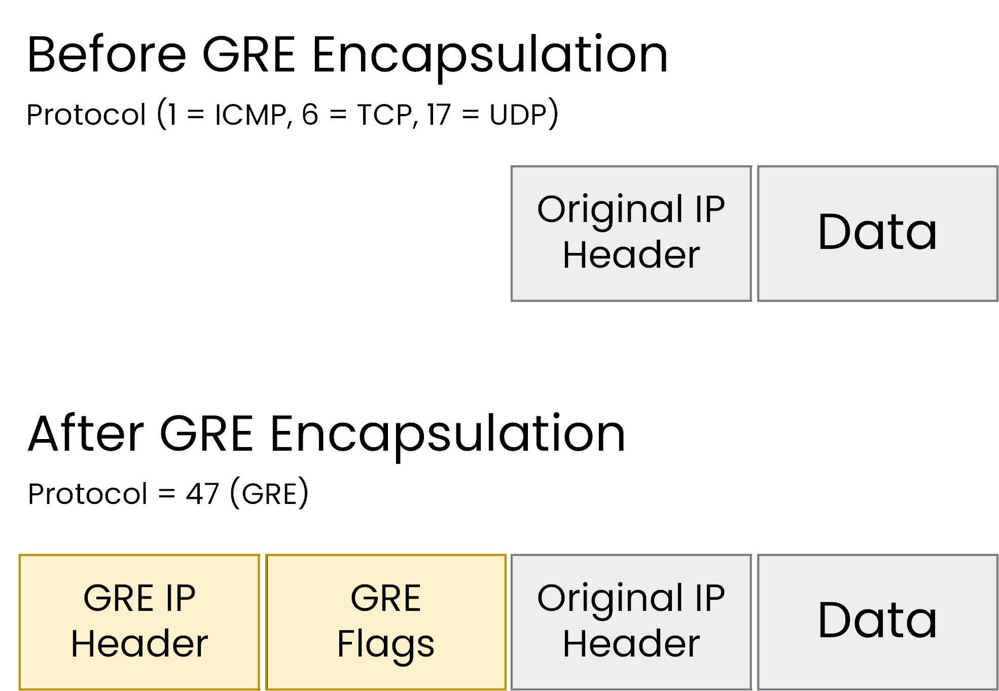
Figure 5 — IP packet before and after GRE encapsulation
During encapsulation, the router adds an outer IP header and a GRE header in front of the original packet so it can travel across the underlay network.
This encapsulation adds approximately 24 bytes of overhead (20 bytes for the outer IP header and 4 bytes for the GRE header), which reduces the effective MTU of the tunnel.
When the packet reaches the destination router, the GRE headers are removed and the original packet is forwarded to the destination network.
Answer the question below
What process does GRE use to wrap the original packet before sending it through the tunnel?
Now that you understand why GRE is used, we can build the tunnel.
In this lab, R1 and R2 are connected through two ISP routers across the Internet.
The Internet acts as the underlay network, while the GRE tunnel will create the overlay connection between the two sites.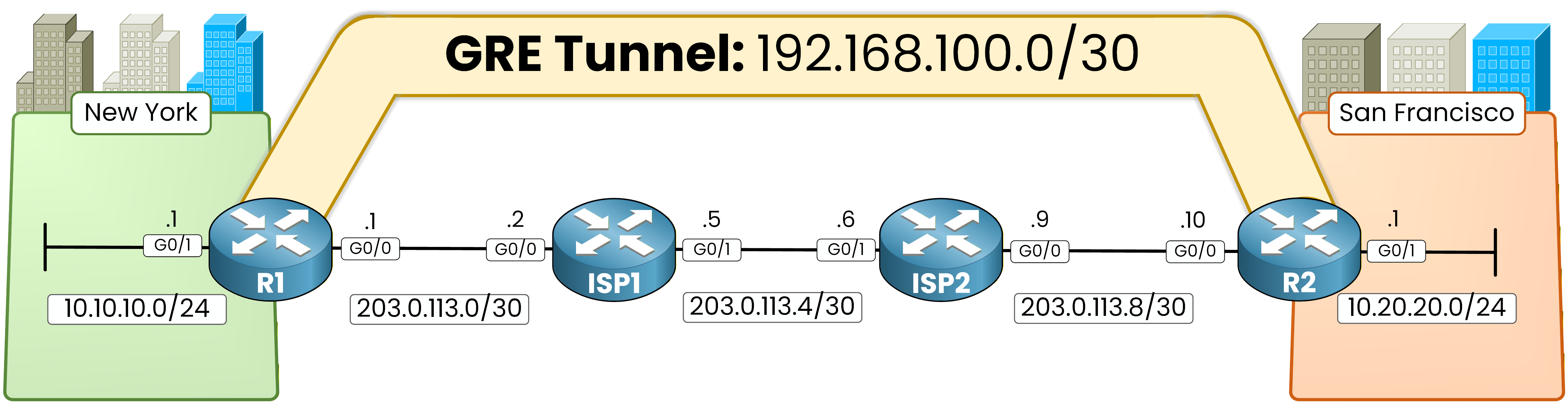
Figure 6 - GRE lab topology
Before creating the GRE tunnel, the underlay network must be working correctly.
This means the ISP routers must be able to route traffic between the tunnel endpoints.Routing
First, configure static routes on the ISP routers so they can forward traffic between the tunnel endpoints.
This ensures the underlay network can reach the GRE tunnel endpoints.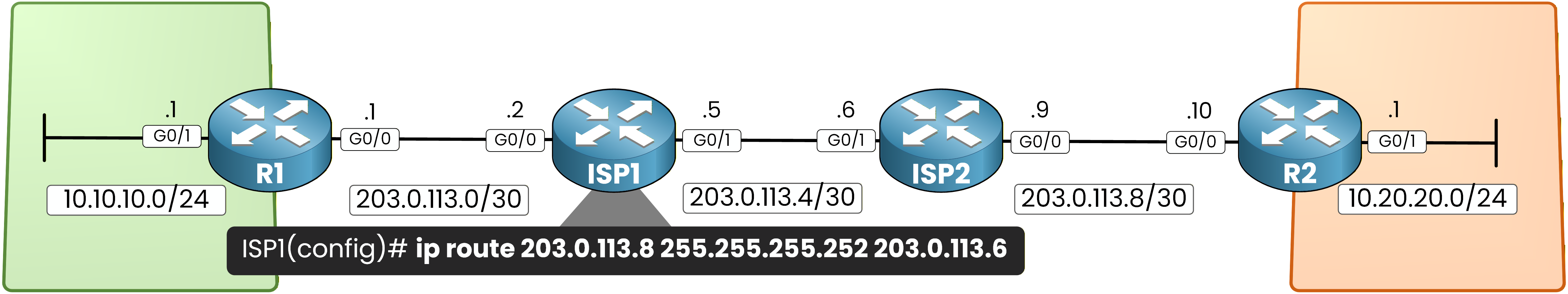
Figure 7 - ISP1 static routing
ISP1 Static Routing
ISP1 must know how to reach the remote WAN link behind ISP2.
On ISP1, configure the following static route:ISP1# conf t Enter configuration commands, one per line. End with CNTL/Z. ISP1(config)# ip route 203.0.113.8 255.255.255.252 203.0.113.6This route allows ISP1 to forward traffic toward the remote WAN subnet behind ISP2.
ISP2 Static Routing
ISP2 must also know how to reach the remote WAN link behind ISP1.
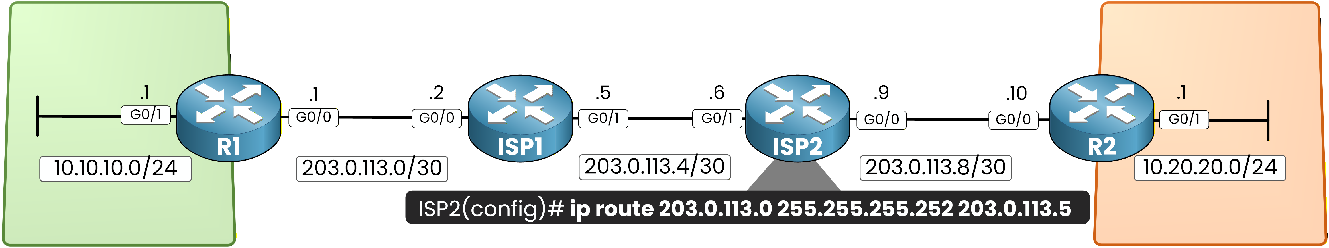
Figure 8 - ISP2 static routing
Configure the following route on ISP2:
ISP2# conf t
Enter configuration commands, one per line.  End with CNTL/Z.
ISP2(config)# ip route 203.0.113.0 255.255.255.252 203.0.113.5
At this stage, the underlay network can route traffic between R1 and R2.
OSPF over GRE
Once the tunnel is created, we will run OSPF across the GRE tunnel so the routers can exchange routes dynamically.
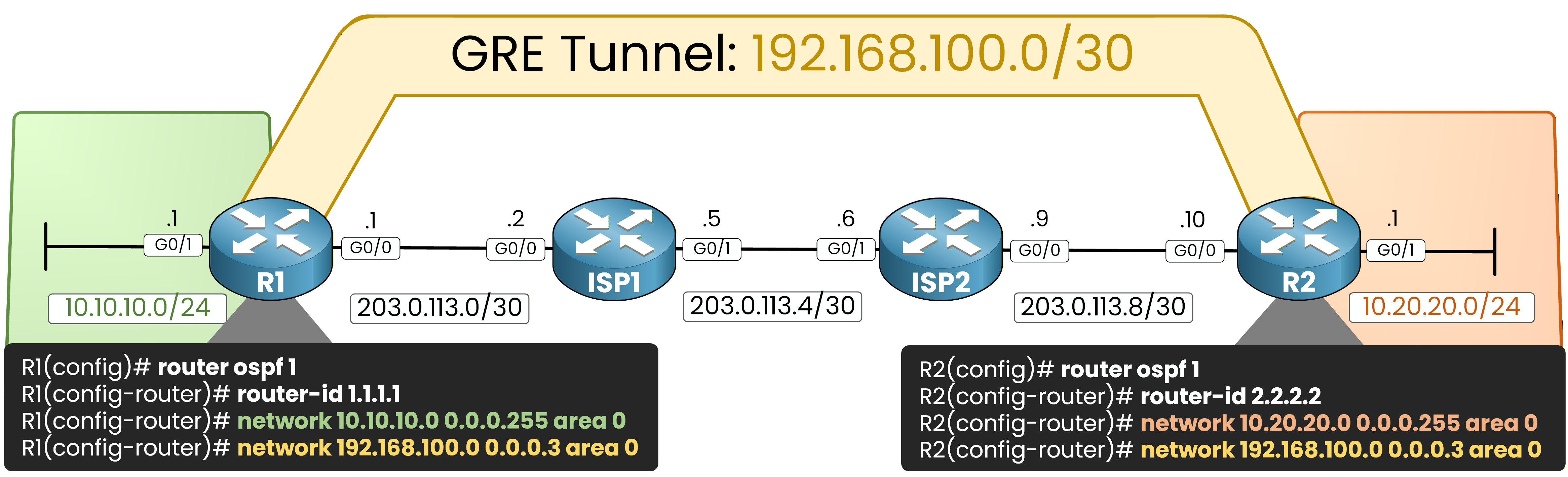
Figure 9 - OSPF over GRE
On R1:
40 % Complete: you’re making great progress
Ready to pass your CCNP exam?