Your Phase 1 network is operational: mGRE on the hub, point-to-point tunnels on the spokes, and EIGRP routing active.
Chicago reaches Miami, but every packet still hairpins through New York.This lesson removes that detour at the tunnel layer.
Starting Point
Here is the addressing layout for this lesson:
Router
Tunnel IP
Public IP (NBMA)
R1, New York
192.168.100.1
203.0.113.1
R3, Chicago
192.168.100.3
203.0.113.3
R4, Miami
192.168.100.4
203.0.113.4
Table 1 – Tunnel and public addresses
In Phase 1, the hub runs mGRE, but each spoke relies on a point-to-point GRE tunnel bound to a hardcoded hub destination (
tunnel destination 203.0.113.1).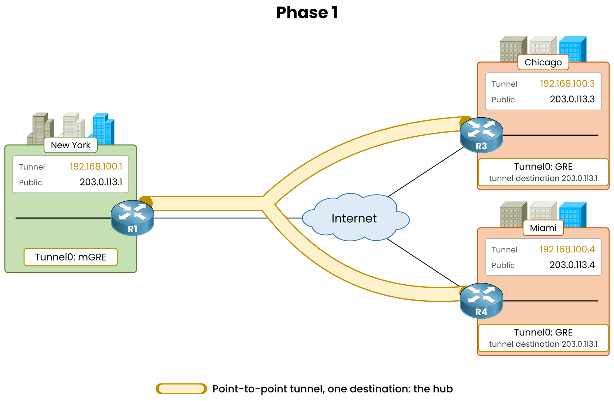
Figure 1 – Phase 1: single fixed destination per spoke
What Changes in Phase 2
Phase 2 modifies one fundamental setting: spokes transition to mGRE.
Without a fixed destination, a spoke can dynamically encapsulate GRE packets directly to any public IP address, including other spokes.
The hub retains its role as the Next Hop Server (NHS); no configuration changes are required on R1.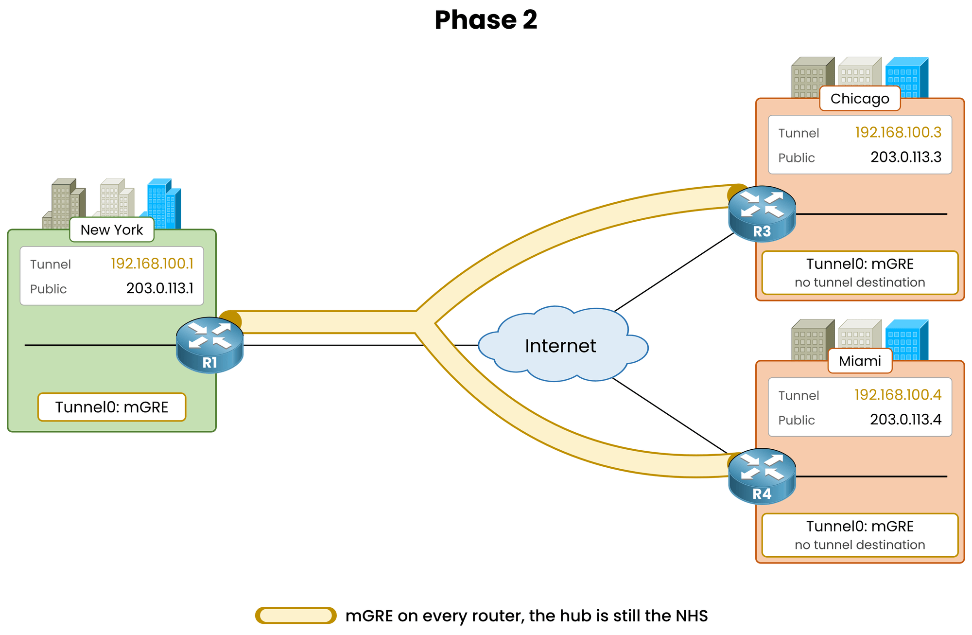
Figure 2 – Phase 2: mGRE on every router
Answer the question below
Click on Complete to continue
Two commands per spoke. The hub configuration remains untouched.
Convert Chicago to mGRE
On Chicago, remove the fixed tunnel destination and switch the tunnel mode to multipoint:
R3# conf t
R3(config)# interface tunnel0
R3(config-if)# no tunnel destination 203.0.113.1
%LINEPROTO-5-UPDOWN: Line protocol on Interface Tunnel0, changed state to down
%DUAL-5-NBRCHANGE: EIGRP-IPv4 100: Neighbor 192.168.100.1 (Tunnel0) is down: interface down
R3(config-if)# tunnel mode gre multipoint
%LINEPROTO-5-UPDOWN: Line protocol on Interface Tunnel0, changed state to up
%DUAL-5-NBRCHANGE: EIGRP-IPv4 100: Neighbor 192.168.100.1 (Tunnel0) is up: new adjacency
R3(config-if)# end
Removing the static destination brings the point-to-point tunnel down and breaks the EIGRP adjacency.
Enabling multipoint mode restores both immediately.
R3 still reaches the hub without a static tunnel destination because the NHRP configuration contains the NHS mapping:
ip nhrp nhs 192.168.100.1 nbma 203.0.113.1 multicast.Convert Miami to mGRE
Apply the same commands on Miami:
R4# conf t
R4(config)# interface tunnel0
R4(config-if)# no tunnel destination 203.0.113.1
%LINEPROTO-5-UPDOWN: Line protocol on Interface Tunnel0, changed state to down
%DUAL-5-NBRCHANGE: EIGRP-IPv4 100: Neighbor 192.168.100.1 (Tunnel0) is down: interface down
R4(config-if)# tunnel mode gre multipoint
%LINEPROTO-5-UPDOWN: Line protocol on Interface Tunnel0, changed state to up
%DUAL-5-NBRCHANGE: EIGRP-IPv4 100: Neighbor 192.168.100.1 (Tunnel0) is up: new adjacency
R4(config-if)# end
Verify the Overlay
Verify the transport parameters on Chicago:
R3# show interfaces tunnel0
Tunnel0 is up, line protocol is up
! Output omitted for brevity
  Tunnel source 203.0.113.3 (GigabitEthernet0/0)
  Tunnel protocol/transport multi-GRE/IP
The output displays
multi-GRE/IPwith no explicit destination line, matching the hub's interface layout.Confirm that the spoke remains registered with the NHS:
R3# show dmvpn
! Output omitted for brevity
Interface: Tunnel0, IPv4 NHRP Details
Type:Spoke, NHRP Peers:1,

 # Ent  Peer NBMA Addr Peer Tunnel Add State  UpDn Tm Attrb
 ----- --------------- --------------- ----- -------- -----
     1 203.0.113.1        192.168.100.1   UP 00:00:41     S
The spoke shows one static peer (
S) for the hub with a state ofUP.
Answer the question below
Which keyword turns a spoke's Tunnel0 into a multipoint GRE interface?
R3 can now encapsulate GRE packets to any public IP address, but it does not yet know the public IP associated with Miami (
192.168.100.4).Trigger the Resolution
Enable NHRP debugging on Chicago and ping Miami's tunnel IP:
R3# debug nhrp
NHRP protocol debugging is on
R3# ping 192.168.100.4
Type escape sequence to abort.
Sending 5, 100-byte ICMP Echos to 192.168.100.4, timeout is 2 seconds:
!!!!!
Success rate is 100 percent (5/5), round-trip min/avg/max = 52/62/104 ms
All five ICMP requests succeed.
The first packet incurs higher latency (104 ms) while traversing the hub during NHRP resolution.
Subsequent packets use the dynamic spoke-to-spoke tunnel at 52 ms.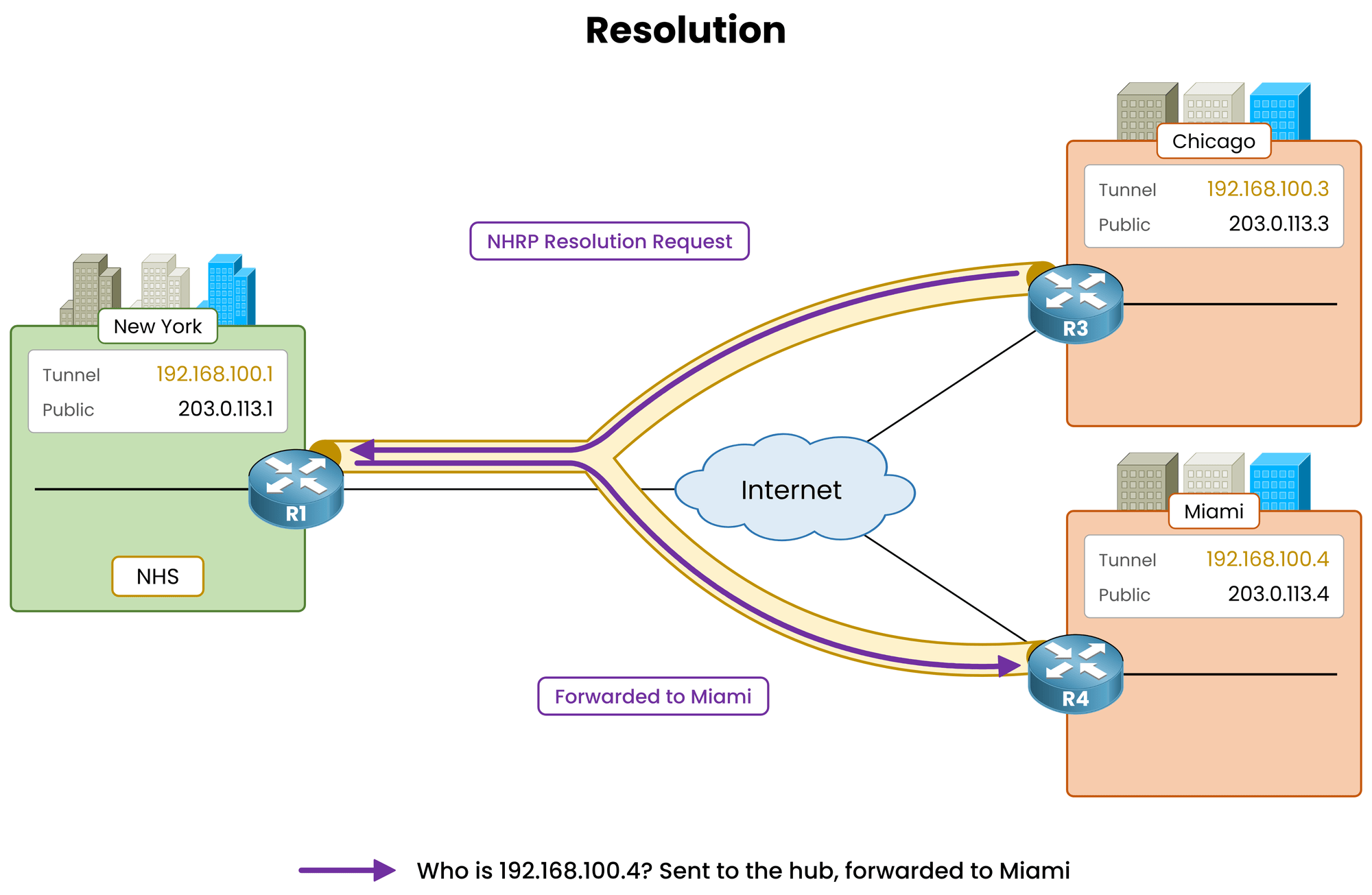
Figure 3 – The spoke requests Miami's public IP
Direct Resolution Reply
The hub forwards the Resolution Request to Miami.
Miami sends its Resolution Reply directly to Chicago rather than routing it back through the hub.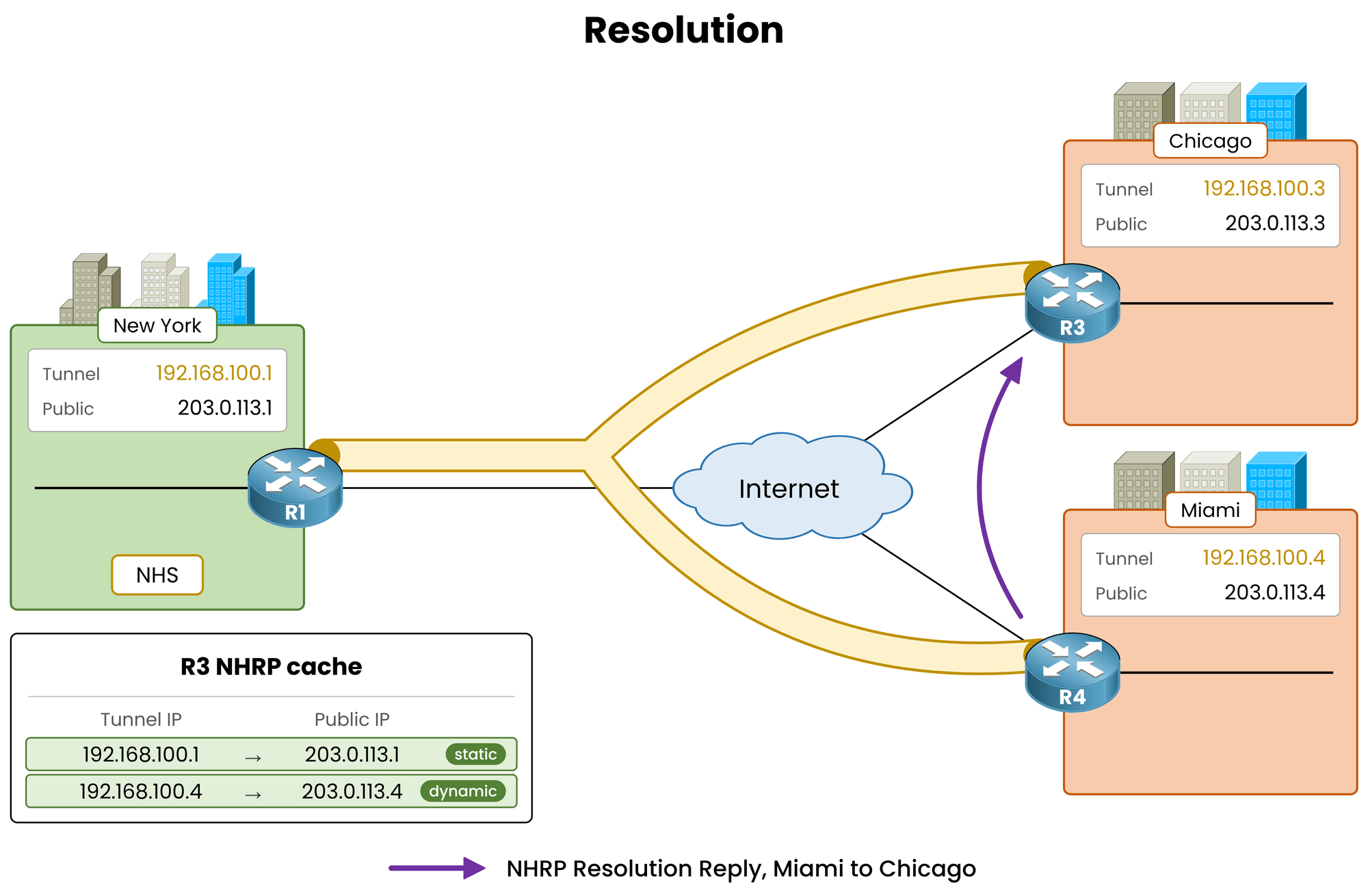
Figure 4 – Miami responds directly to Chicago
Review the debug output printed on R3's console:
! Output omitted for brevity
NHRP: Send Resolution Request via Tunnel0 vrf global(0x0), packet size: 92
 src: 192.168.100.3, dst: 192.168.100.4
NHRP: Receive Resolution Reply via Tunnel0 vrf global(0x0), packet size: 132
 src: 192.168.100.4, dst: 192.168.100.3
NHRP: Adding Tunnel Endpoints (VPN: 192.168.100.4, NBMA: 203.0.113.4)
The exchange follows three steps:
Send Resolution Request: R3 queries the NHS (hub) for the public IP mapped to 192.168.100.4.
Receive Resolution Reply: Miami sends a direct reply containing its NBMA address (203.0.113.4).
Adding Tunnel Endpoints: R3 adds the mapping to its NHRP cache and dynamically builds a GRE tunnel to 203.0.113.4.
Answer the question below
Which router answers Chicago's NHRP Resolution Request for 192.168.100.4?
The mapping is cached. Verify that packet transport bypasses the hub.
Trace the Direct Path
Verify latency and trace the path from Chicago to Miami:
R3# ping 192.168.100.4
Type escape sequence to abort.
Sending 5, 100-byte ICMP Echos to 192.168.100.4, timeout is 2 seconds:
!!!!!
Success rate is 100 percent (5/5), round-trip min/avg/max = 52/52/52 ms
R3# traceroute 192.168.100.4
Type escape sequence to abort.
Tracing the route to 192.168.100.4
VRF info: (vrf in name/id, vrf out name/id)
  1 192.168.100.4 52 msec *  52 msec
The ping confirms a stable 52 ms latency over the established tunnel.
Thetraceroutedisplays a single direct hop to Miami (192.168.100.4), with the missing probe caused by standard IOS ICMP rate limiting.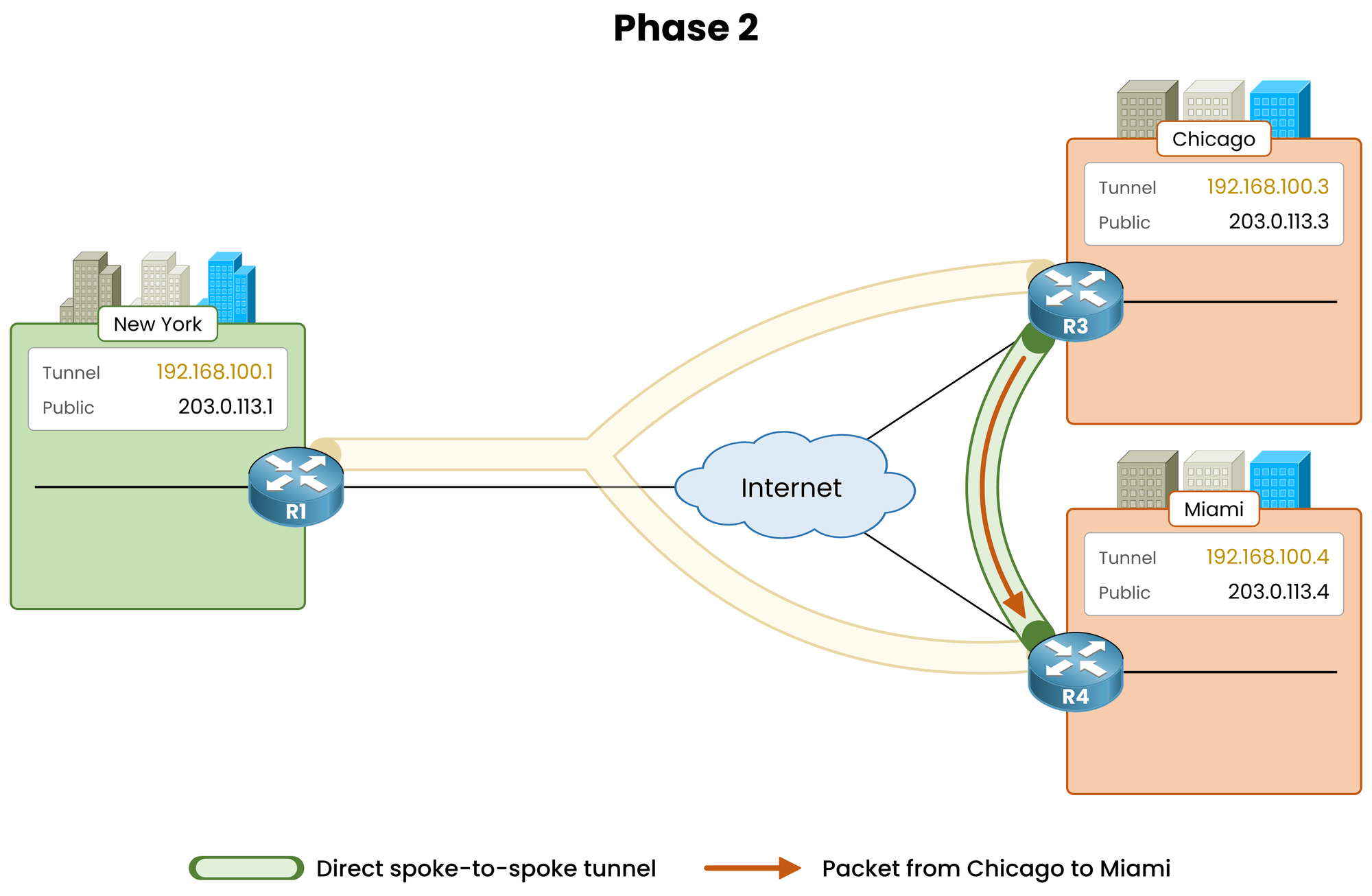
Figure 5 – Phase 2: spoke-to-spoke traffic crosses the public network directly
Check DMVPN Peers and NHRP Cache
Inspect the DMVPN peer table on Chicago:
R3# show dmvpn
! Output omitted for brevity
Interface: Tunnel0, IPv4 NHRP Details
Type:Spoke, NHRP Peers:2,

 # Ent  Peer NBMA Addr Peer Tunnel Add State  UpDn Tm Attrb
 ----- --------------- --------------- ----- -------- -----
     1 203.0.113.1        192.168.100.1   UP 00:03:12     S
     1 203.0.113.4        192.168.100.4   UP 00:00:26     D
Chicago displays two peers: the static hub entry (
S) and the dynamic spoke entry (D) created on demand by NHRP.
Inspect the peer table on the hub:
R1# show dmvpn
! Output omitted for brevity
Interface: Tunnel0, IPv4 NHRP Details
Type:Hub, NHRP Peers:2,

 # Ent  Peer NBMA Addr Peer Tunnel Add State  UpDn Tm Attrb
 ----- --------------- --------------- ----- -------- -----
     1 203.0.113.3       192.168.100.3    UP 00:03:20     D
     1 203.0.113.4       192.168.100.4    UP 00:03:01     D
The hub state remains unchanged. It processed one Resolution Request and stays completely out of the data path.
Verify Chicago's NHRP table:
R3# show ip nhrp
192.168.100.1/32 via 192.168.100.1
   Tunnel0 created 00:21:40, never expire
   Type: static, Flags: used
   NBMA address: 203.0.113.1
192.168.100.4/32 via 192.168.100.4
   Tunnel0 created 00:00:52, expire 00:09:08
   Type: dynamic, Flags: router used nhop
   NBMA address: 203.0.113.4
The hub mapping is static and permanent (
never expire).The Miami mapping is dynamic with a default 600-second holdtime (
00:09:08remaining).
Active traffic resets this timer. When traffic stops, the entry expires and tears down the dynamic tunnel.Production Design Note: Keep the NHRP holdtime between 300 and 600 seconds (
ip nhrp holdtime 600).
Long holdtimes delay convergence if a spoke's public IP changes.Answer the question below
On R3, which attribute does show dmvpn give to the Miami entry?
Answer the question below
When show dmvpn on Chicago lists 2 NHRP peers, how many does show dmvpn on Miami list?
Answer the question below
After 5 minutes with no Chicago-Miami traffic, how many NHRP peers does Chicago list?
Tunnel IP to tunnel IP connectivity is now direct. However, LAN-to-LAN traffic still hairpins through the hub.
Check the LAN Path
Inspect the EIGRP routing table on Chicago:
R3# show ip route eigrp
! Output omitted for brevity

Gateway of last resort is 192.168.100.1 to network 0.0.0.0

D*    0.0.0.0/0 [90/26880256] via 192.168.100.1, 00:04:05, Tunnel0
Chicago relies on a single default route pointing to
192.168.100.1(the hub).
Trace the path to Miami's LAN:R3# traceroute 10.40.40.1 Type escape sequence to abort. Tracing the route to 10.40.40.1 VRF info: (vrf in name/id, vrf out name/id) 1 192.168.100.1 52 msec 52 msec 52 msec 2 192.168.100.4 78 msec * 78 msecThe output displays two hops, routing traffic through New York (
192.168.100.1) before reaching Miami (192.168.100.4).
IOS ICMP rate limiting causes the asterisk on the second hop.The direct spoke-to-spoke tunnel remains unused.
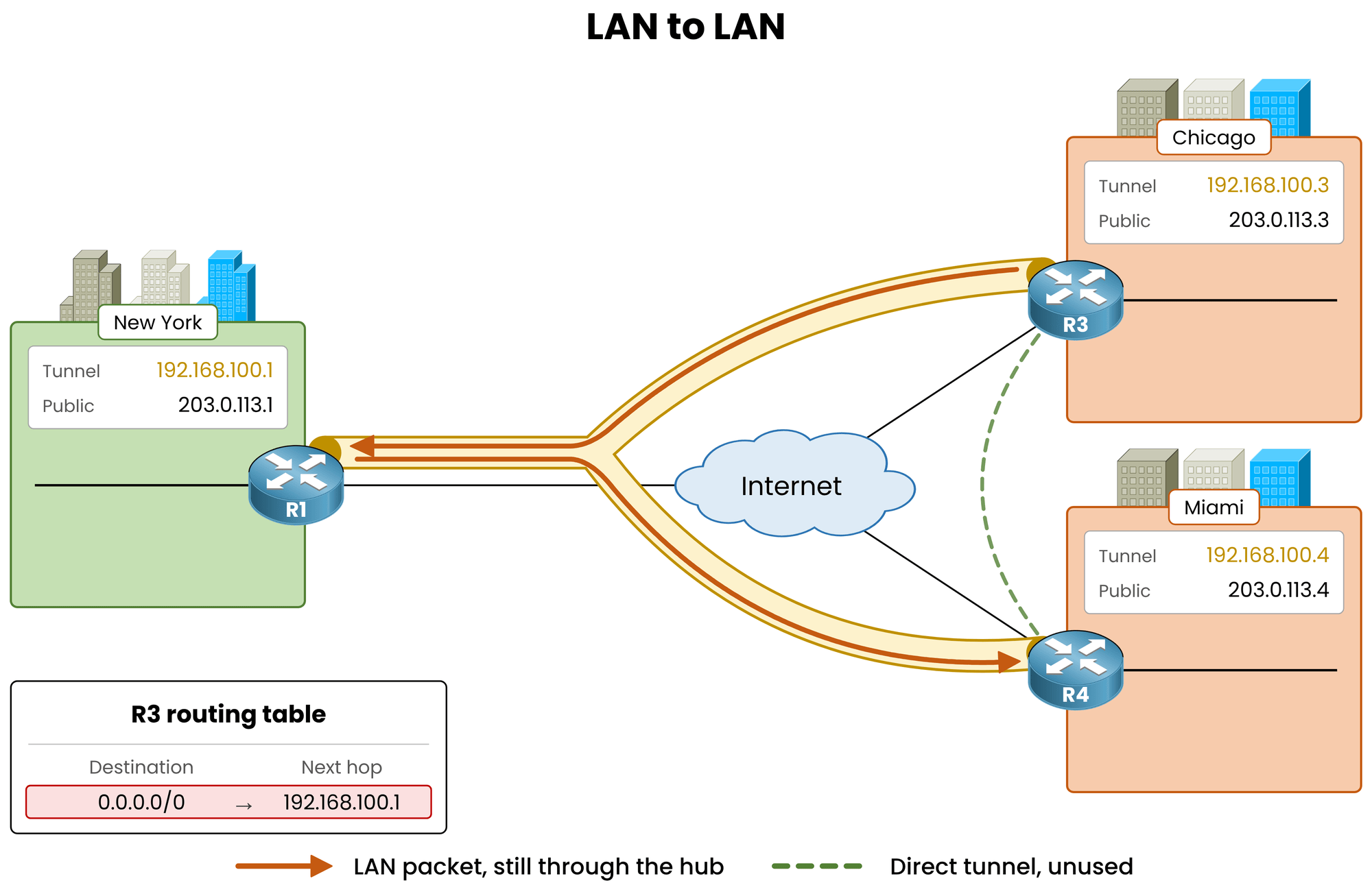
Figure 6 – LAN-to-LAN traffic still hairpins through the hub
Why Next Hop Alignment Matters
The routing table dictates tunnel selection. Because Chicago reaches
10.40.40.0/24through the default route via the hub, it sends LAN traffic straight to R1 without issuing an NHRP Resolution Request for Miami.To trigger a direct spoke-to-spoke tunnel for LAN traffic, the routing table on Chicago must see Miami's tunnel IP (
192.168.100.4) as the explicit next hop. Controlling next-hop propagation is handled by the routing protocol on the hub.Key Takeaway: Phase 2 requires two conditions
Interface layer: mGRE enabled on every spoke (configured in this lesson).
Routing layer: the original spoke IP preserved as the next hop in the routing table (covered in DMVPN Phase 2 EIGRP Routing).
Answer the question below
For a direct tunnel, which tunnel IP must be the next hop of the Miami LAN on R3?