In this lesson, you are going to discover the life of a packet and understand the decisions made at each step.
You might ask yourself: what does “the life of a packet” actually mean?
When two devices communicate on a network, data does not magically appear at the destination. It is sent in packets, and each packet follows a precise path across the network. That journey, from the source to the destination, is what we call the life of a packet, and this is exactly what you are going to follow step by step.
The Communication Scenario
Take a look at the diagram below. Imagine that PC1 wants to communicate with PC2, which is located in a different network.
The packet must cross switches, routers, and multiple IP networks before it can reach its destination.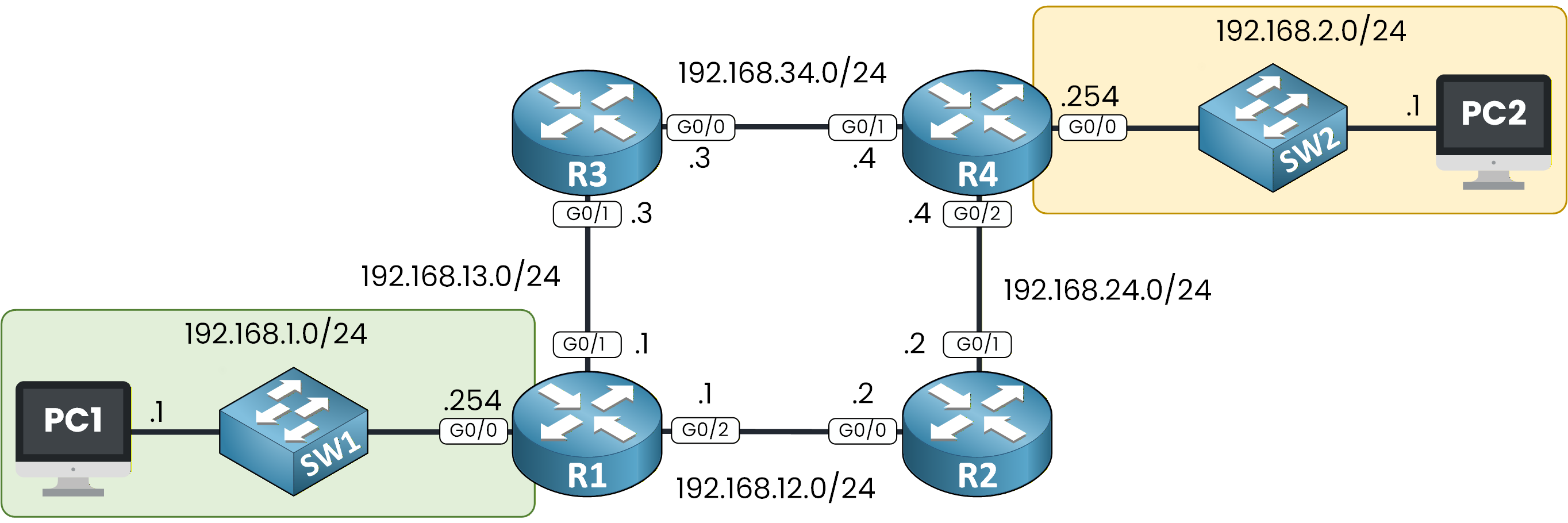
Figure 1 - Network Topology
This diagram shows the networks involved in this communication. You can see the source host, the destination host, and all the intermediate devices that the packet must pass through.
Before going into details, it is important to understand why we are studying this process.
The Goal of This Lesson
The goal of this lesson is to help you understand how a packet moves through a network and how forwarding and routing decisions are made.
This lesson is a bit more challenging than the previous ones, but it is also one of the most important. If you truly understand the logic behind packet behavior, many networking concepts will suddenly become much clearer.
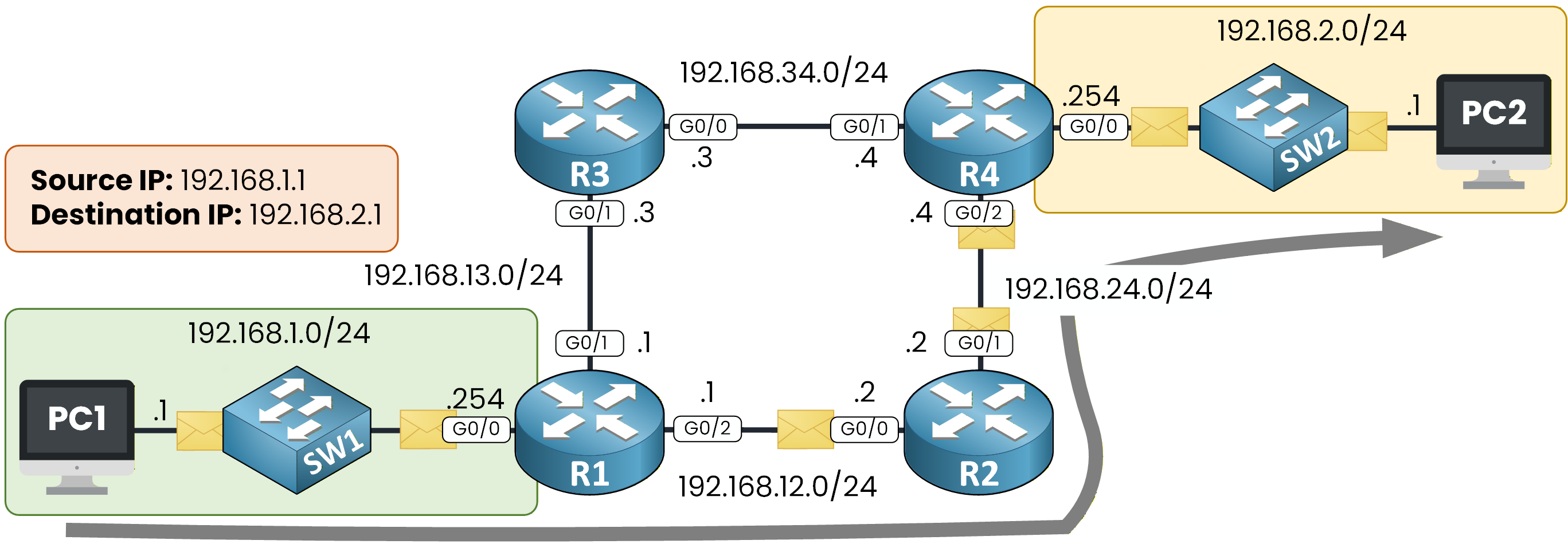
Figure 2 - Life of a Packet Path in the Topology
To explain this process, we will use one example to guide us through it from start to finish: PC1 communicating with PC2.
As you can see below, the arrow represents the path that the packet will take through the network. In the rest of this lesson, our objective is simple: follow that path step by step and understand what happens at each stage.
Let's dive in!
Answer the question below
What do we call the journey of a packet from the source to the destination?
Let’s start from the topology and define the communication we are about to analyze.
PC1 uses the IP address 192.168.1.1 and belongs to the 192.168.1.0/24 network, shown in green.
PC2 uses the IP address 192.168.2.1 and belongs to the 192.168.2.0/24 network, shown in yellow.
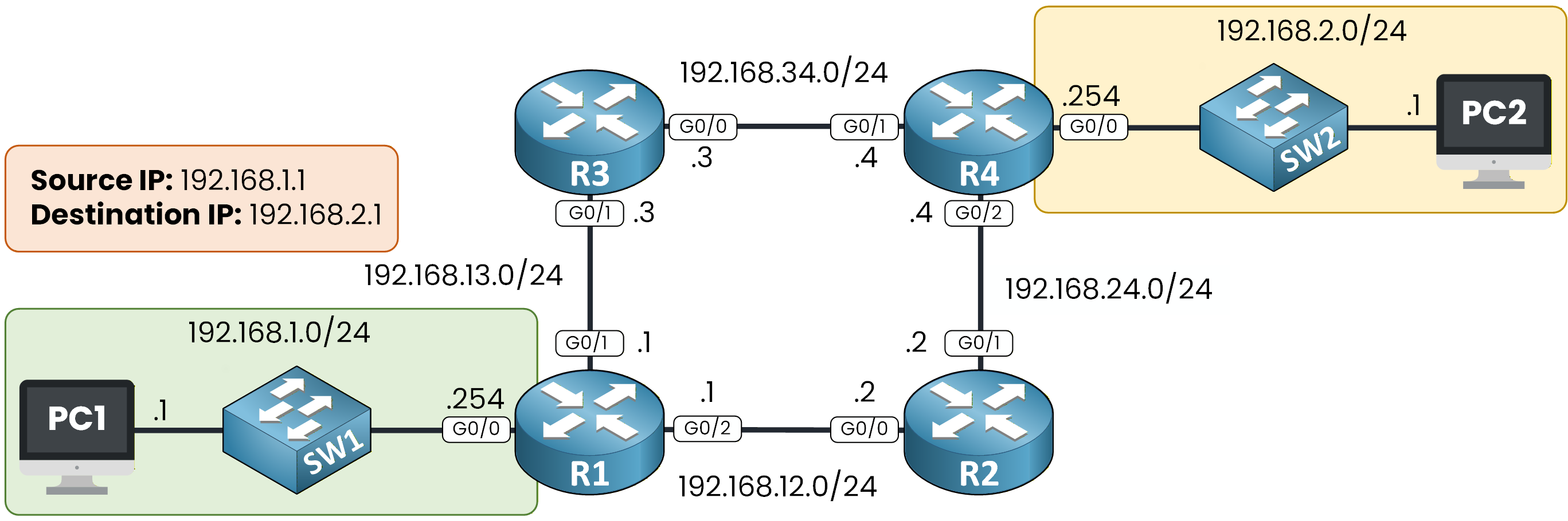
Figure 3 - Network Topology
Local vs Remote Destination
Before sending any packet, PC1 first determines whether the destination is local or remote.
To do this, PC1 compares the destination IP address, 192.168.2.1, with its own subnet, 192.168.1.0/24.
Because the destination IP does not belong to the local subnet, PC1 identifies the destination as remote.This single decision defines the entire forwarding behavior of the host, so make sure this logic is clear before moving on.
Using the Default Gateway
When the destination is remote, PC1 cannot send the packet directly to the destination host.
Instead, it must forward the traffic to its default gateway.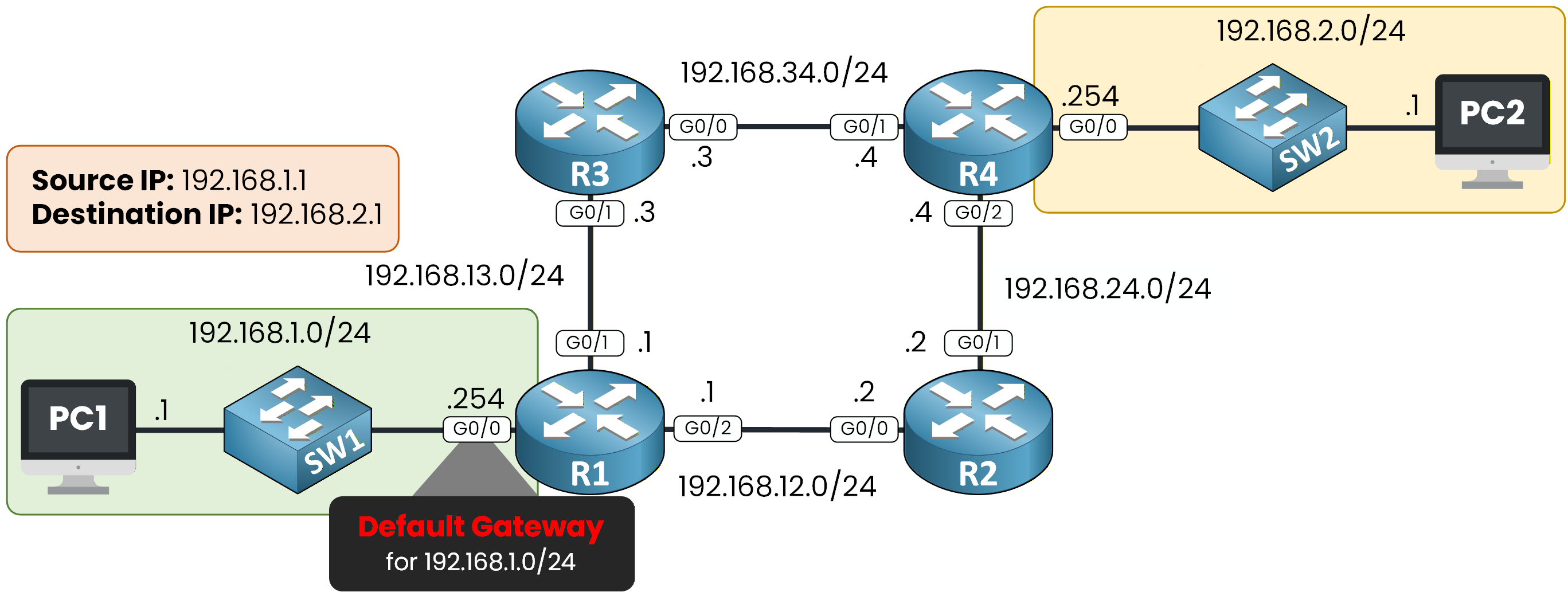
Figure 4 - R1 is the default gateway for 192.168.1.0
The default gateway is the IP address used to exit the local network.
In this topology, the default gateway for the 192.168.1.0/24 network is router R1, using IP address 192.168.1.254.PC1 now knows which device is responsible for forwarding the packet outside the local network.
Answer the question below
Which device does PC1 send the packet to when the destination is remote?
Resolving the Default Gateway MAC Address
PC1 already knows the IP address of the default gateway, but this is not enough to send the packet.
On an Ethernet network, frames are forwarded using MAC addresses.
Before sending anything to R1, PC1 must first learn the MAC address of the router’s interface.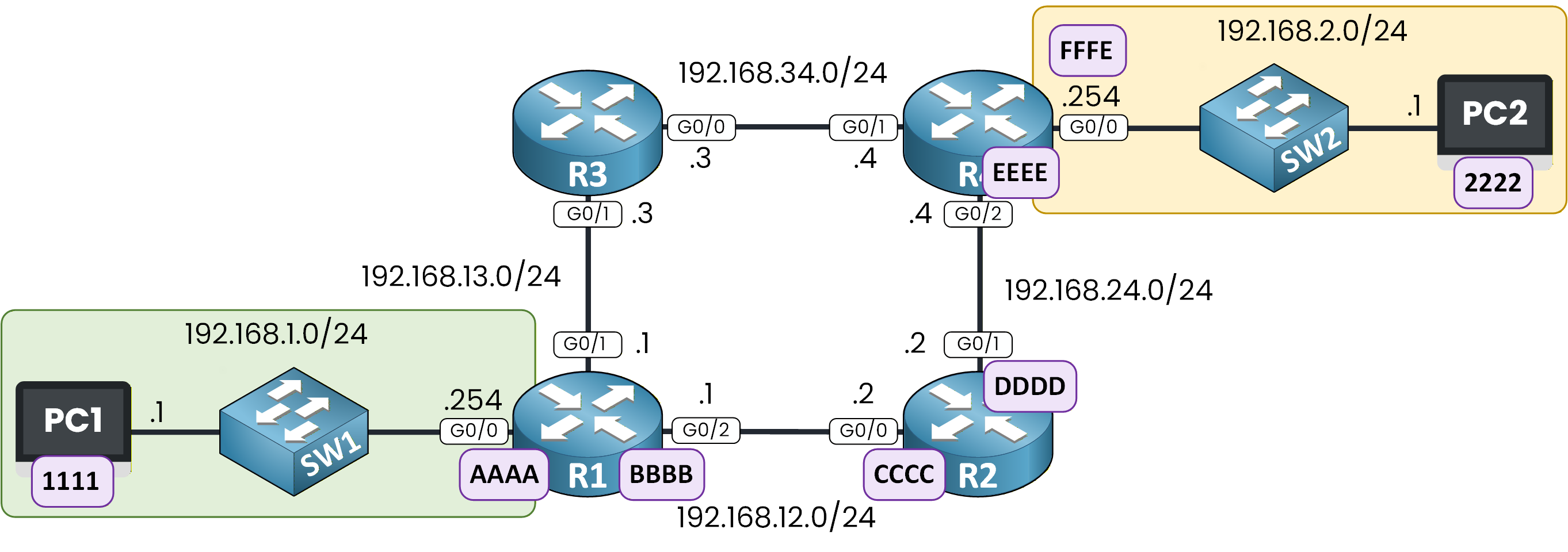
Figure 5 - Network Path with MAC Addresses
The diagram shows the MAC addresses used along the path.
For clarity, the MAC addresses are simplified. In real networks, MAC addresses are 48-bit hexadecimal values.
ARP Request from PC1
To leave the local network, PC1 needs the MAC address of its default gateway.
Throughout this lesson, FFFF.FFFF.FFFF is the Ethernet broadcast address. It is a placeholder used only inside ARP requests, while a device is still waiting to learn a real MAC address. It never appears as the destination MAC of an actual data frame: by the time PC1 (or any router) sends real traffic, FFFF.FFFF.FFFF has already been replaced by the real MAC address learned through ARP (for example AAAA for R1, or 2222 for PC2).
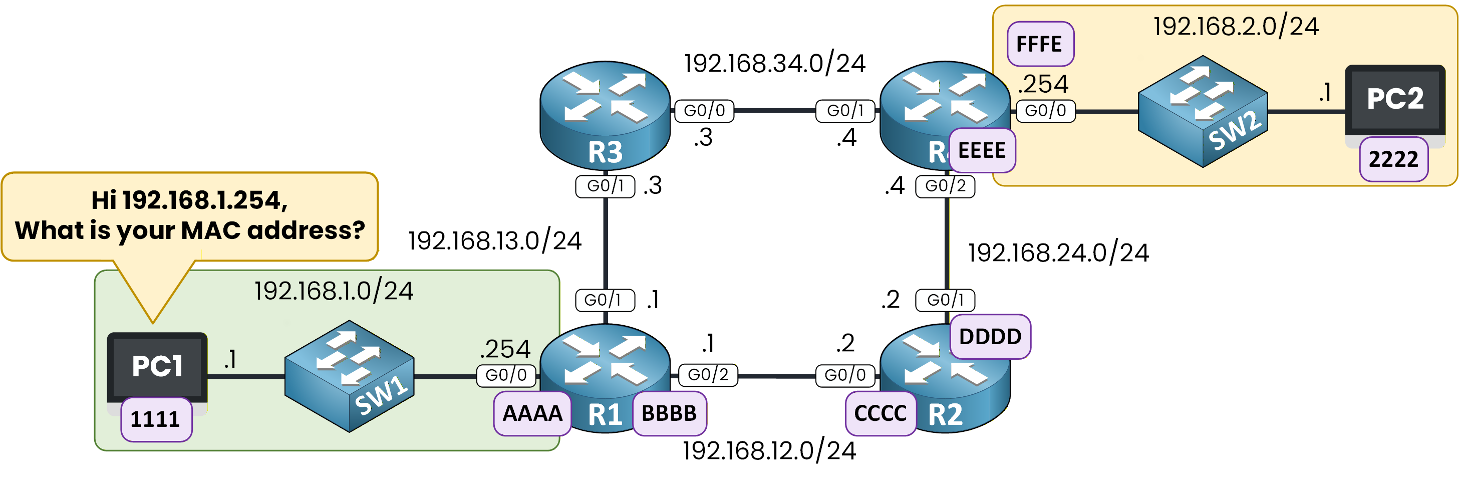
Figure 6 - PC1 Asks for the MAC Address
PC1 is configured with 192.168.1.254 as the default gateway, but it does not yet know the associated MAC address.
To resolve this, PC1 sends an ARP request.The ARP request contains:
Source IP: 192.168.1.1
Destination IP: 192.168.1.254
Destination MAC: FFFF.FFFF.FFFF
Source MAC: 1111
The broadcast destination MAC ensures that all devices in the local network receive the request.
Only the device owning IP address 192.168.1.254 will reply.During this ARP exchange, the destination IP (192.168.1.254) and the destination MAC (FFFF.FFFF.FFFF) don’t match the same device yet, and that’s expected: PC1 doesn’t know R1’s real MAC address, which is exactly why it sends this ARP request. R1’s reply confirms that 192.168.1.254 is associated with MAC AAAA.
But once PC1 builds the actual packet for PC2 (see below), the destination IP and destination MAC belong to two different devices again: the destination IP is 192.168.2.1 (PC2, the final destination), while the destination MAC is AAAA (R1, the next hop). This is normal: the destination MAC always points to the next hop, not necessarily to the final destination, unless that next hop is the destination itself.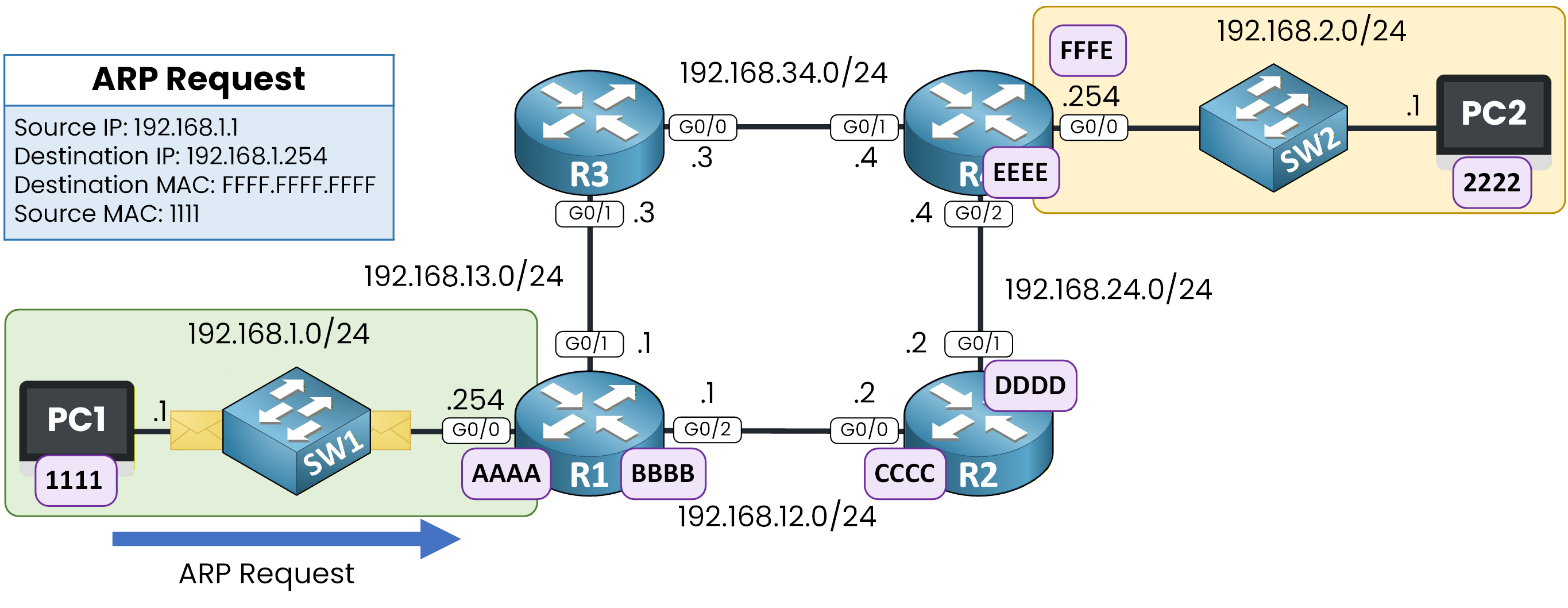
Figure 7 - ARP Request to R1
ARP Reply from R1
The device with IP address 192.168.1.254 receives the ARP request and recognizes itself as the destination.
R1 sends an ARP reply directly to PC1, indicating that IP address 192.168.1.254 is associated with MAC address AAAA.
This MAC address corresponds to the router’s G0/0 interface.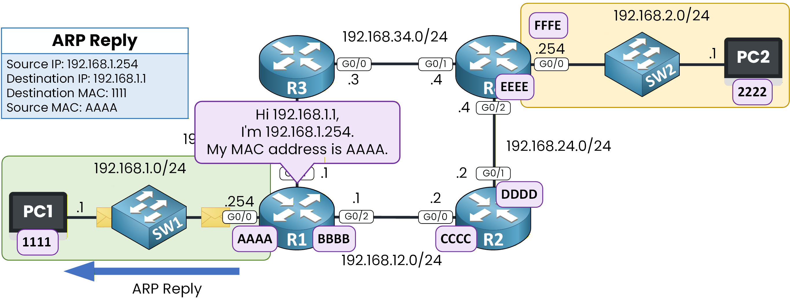
Figure 8 - ARP Reply from R1
At this point, PC1 knows the MAC address of its default gateway.
PC1> arp -a
Internet Address      Physical Address      Type
192.168.1.254         AAAA-AAAA-AAAA        dynamic
It can now send the packet.
PC1 builds the frame with:Source IP: 192.168.1.1
Destination IP: 192.168.2.1
Destination MAC: AAAA
Source MAC: 1111
The packet is forwarded to R1, and the forwarding process continues.
40 % Complete: you’re making great progress
Ready to pass your CCNA exam?