Root Guard Spanning Tree is a tool used to stabilize the STP topology. By using Root Guard, we can control the placement of the Root Bridge.
To explain the use case of Root Guard, let’s consider a scenario where you are working for a service provider on the right and you need to connect a customer to your infrastructure.
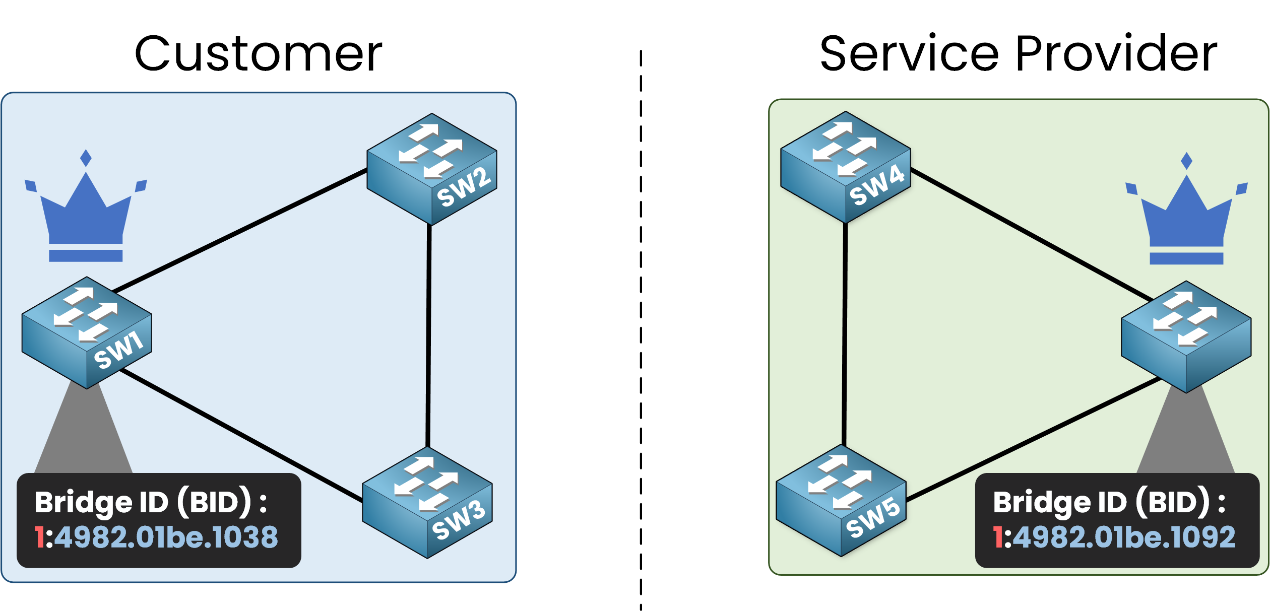
Figure 1 – Two separate STP topologies: one for the customer, one for the service provider
In this example, the customer requires access to the service provider’s infrastructure to reach the internet.
In the diagram, you can see two distinct STP topologies, one for each network.
When the service provider network connects to the customer network, BPDUs will start flowing between the two STP topologies. As a service provider, we do not want our Root Bridge to be located in the customer’s network.
Answer the question below
What does Root Guard help the service provider keep control of?
Here is the connection of our topology:
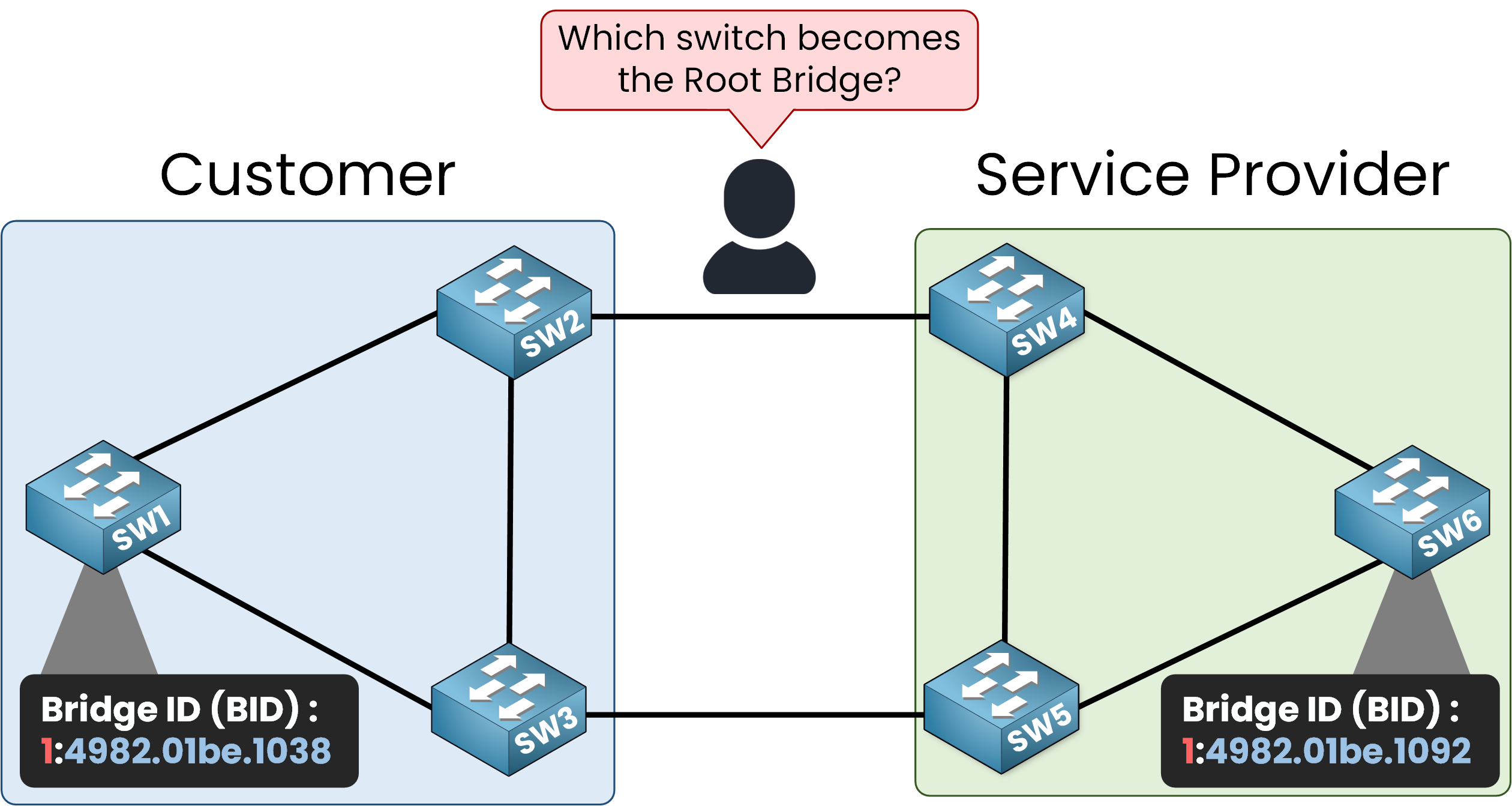
Figure 2 – Which switch becomes Root? BID values determine the STP election result
By default, Cisco switches operate using the Per VLAN Spanning Tree Plus (PVST+) protocol. This protocol creates a separate STP instance for each VLAN.
SW6 in the service provider’s STP topology is configured as the desired Root Bridge with a priority of
0+ VLAN 1, resulting in a BID (1:4982:01be:1092).SW1 in the customer’s STP topology is configured with a priority of
0+ VLAN 1, resulting in a BID (1:4982:01be:1038).The other switches use the default priority (32,768 + VLAN 1).
BID Comparison
Since the switch with the lowest BID becomes the Root Bridge in the STP topology, we have the following BIDs:
1:4982:01be:1038 (SW1)
1:4982:01be:1092 (SW6)
As BPDUs are exchanged, SW1 with the lower BID claims to be the Root Bridge and SW6 recognizes it as such.
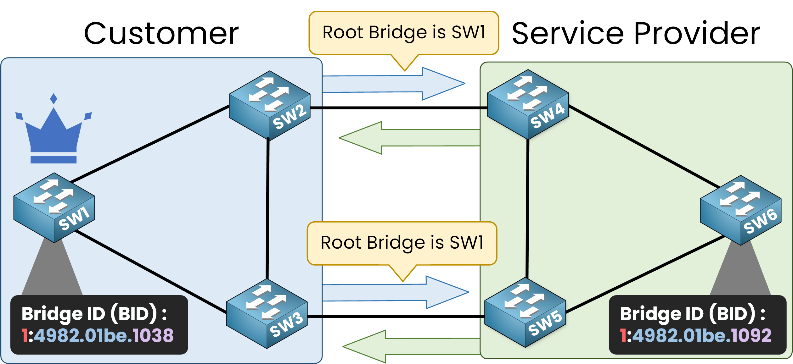
Figure 3 – SW1 wins the Root Bridge election due to lower Bridge ID
Consequences of No Security Measures
Since no security measures are enabled, the service provider’s switches (SW4, SW5, and SW6) assume that SW1 is the new Root Bridge of the topology.
This is a serious issue because all traffic will be redirected to the Root Bridge. The port roles change to align with the new topology.
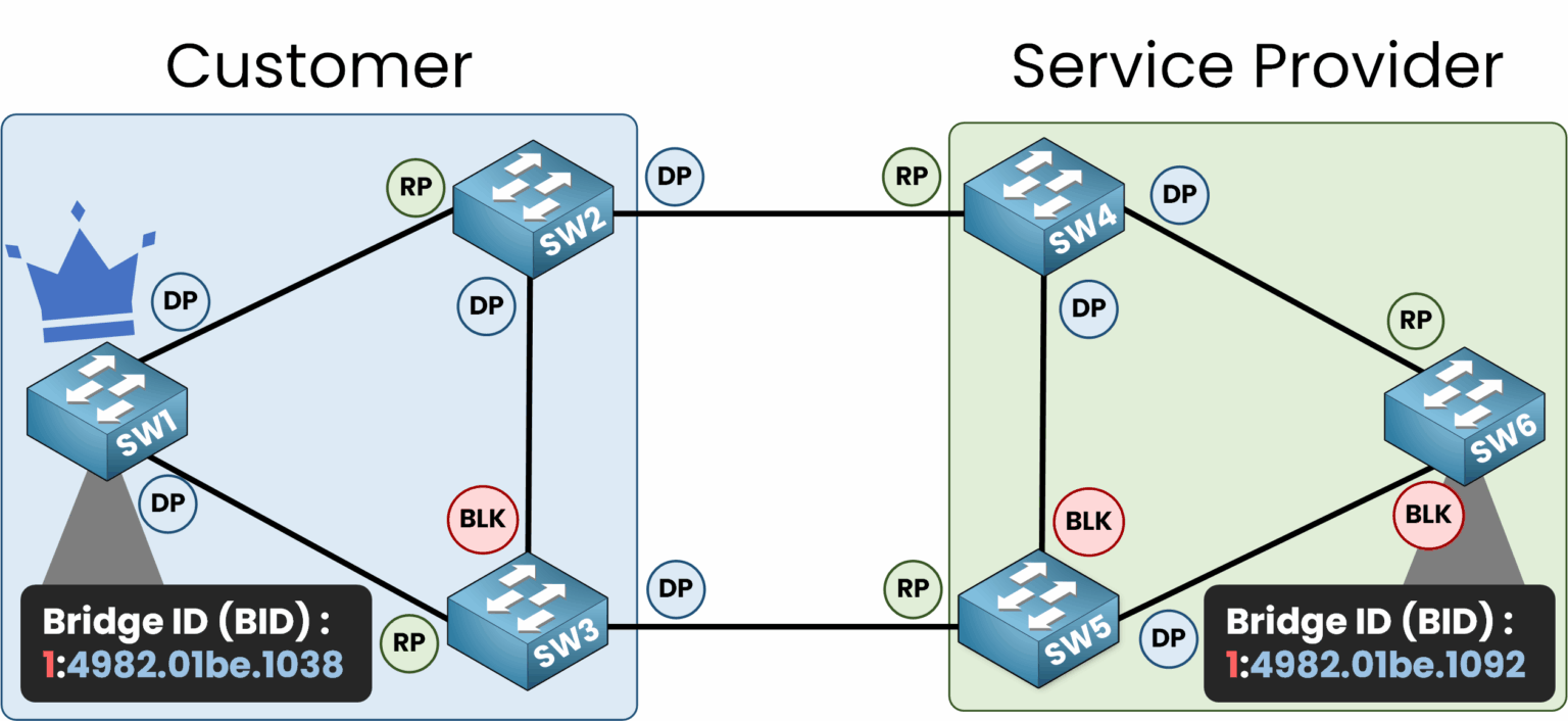
Figure 4 – Port roles change after SW1 becomes Root Bridge
In this scenario, SW1 becomes the Root Bridge, and all traffic, even between switches like SW5 and SW6, is forwarded through SW1.
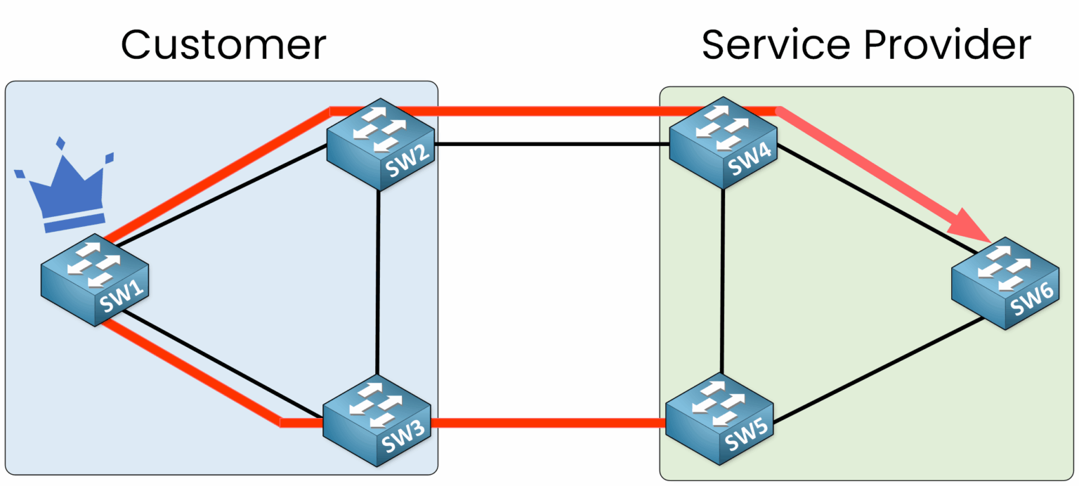
Figure 5 – All traffic is redirected through the customer’s Root Bridge
This setup is undesirable. We want to ensure that the service provider’s STP topology always retains control of the Root Bridge.
Answer the question below
What value decides which switch becomes Root Bridge?
Root Guard prevents superior BPDUs from being accepted on specific ports by treating them as untrusted. By enabling Root Guard on the interfaces facing the customer’s network on SW4 and SW5, we can ensure the integrity of the service provider’s STP topology.
40 % Complete: you’re making great progress
Ready to pass your CCNA exam?