OSPF Neighbor States

Introduction

Before routers can exchange routing information using OSPF, they must first form a neighbor relationship. This process happens through a sequence of OSPF Neighbor States, each representing a step toward full database synchronization.

Let’s break down each state by using an example with :

  • R1 - Router ID 1.1.1.1

  • R2 - Router ID 2.2.2.2

🔗 If you haven’t already, start with the OSPF Router ID lesson to understand how each router identifies itself in OSPF.

Step 1 – Down

This is the starting point.
OSPF is enabled on the interface, but no Hello packets have been sent or received.

OSPF Down state where routers haven't exchanged any Hello packets yet

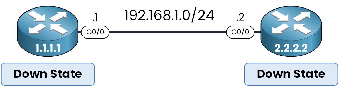
Figure 1 – Two OSPF routers in Down state, no Hello packets exchanged.

The neighbor table is empty, and the router is simply waiting for communication.

Step 2 – Init

The router begins sending Hello packets to 224.0.0.5, the multicast address used by OSPF enabled routers.

OSPF neighbor state transitions from Down to Init as the first Hello packet is sent

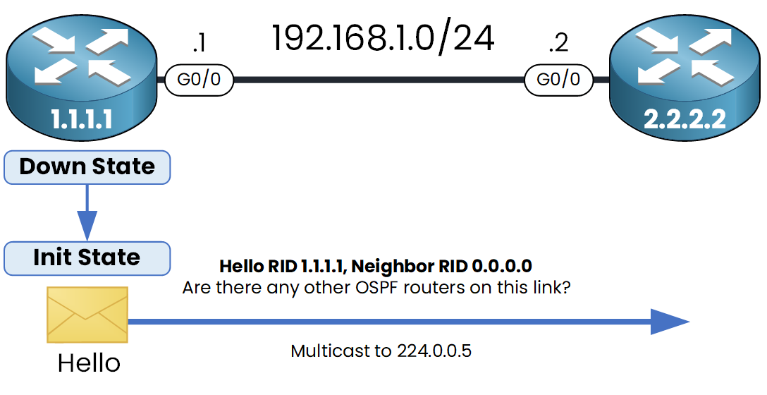
Figure 2 – OSPF Init state.

Each Hello packet includes:

  • The Router ID: 1.1.1.1

  • Neighbor ID: 0.0.0.0 (no neighbors seen yet)

  • The Area ID

  • Hello and Dead timers

At this stage, the router is saying:

I’m here, and I’m ready to form neighbors if we match our Area ID and Hello and Dead Timers interval.

Step 3 – Two-Way

Another router (let’s say R2) receives the Hello from R1 and responds with a Hello packet.
R2 includes both its own Router ID and the Router ID of R1.

OSPF neighbor state reaches 2-Way after routers exchange Hello packets and acknowledge each other

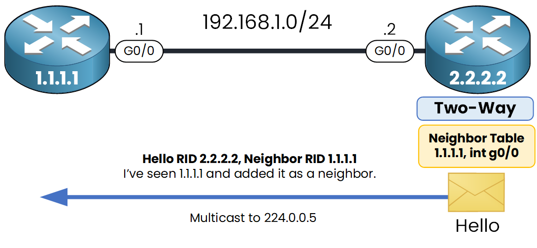
Figure 3 – OSPF Two-Way state.

When R1 sees its own ID in R2’s Hello, it knows:

“This router has seen me. We can now become neighbors.”

R1 adds R2 to its neighbor table and sends a final Hello packet to inform R2 that it recognizes it as a neighbor.

OSPF Two-Way state neighbor table update after Hello exchange

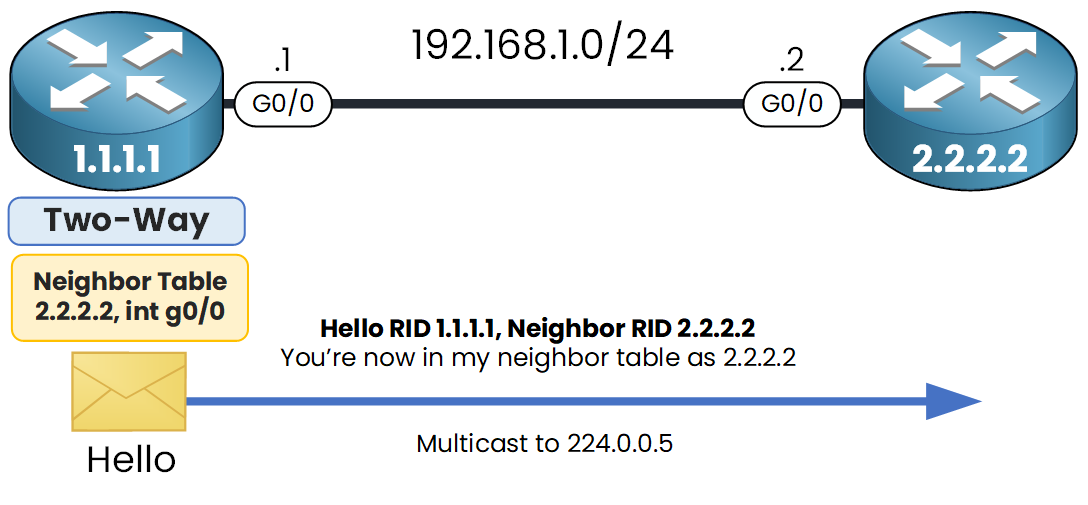
Figure 4 – Mutual neighbor confirmation; Two-Way reached.

Both routers now add each other to their neighbor table.
They have reached the Two-Way state.

Each router now lists the other in its neighbor table, confirming the Two-Way state

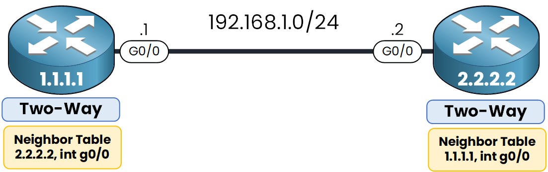
Figure 5 – Both routers list each other as neighbors in Two-Way state.

What happens next depends on the network type:

  • On point-to-point links, the routers go directly to ExStart State

  • On Ethernet networks, a DR/BDR election must happen first

Don’t worry about DR/BDR now we’ll cover that in the next lesson. You don’t need to fully understand it here.

Database Synchronization - Exchange LSAs

Once routers reach the Two-Way state, they are ready to synchronize their Link-State Databases (LSDBs). This process ensures both routers have the same view of the network topology. It happens in four more steps.

Step 4 – ExStart

Before exchanging link-state information, routers must agree on who will send the first Database Description (DBD) packet.

Both routers initially claim to be the master by sending a DBD with their own Router ID.

During ExStart, both routers attempt to claim the master role by sending DBD packets

Figure 6 – OSPF ExStart state, master role negotiation.

The router with the highest Router ID wins the election and becomes the master, taking control of the exchange process.

Step 5 – Exchange

Since R2 has the higher Router ID, it sends the first Database Description (DBD) packets, summarizing its LSDB contents.

Routers in Exchange state share LSDB summaries using DBD and LSAck packets

Figure 7 – OSPF Exchange state, LSDB summaries swapped.

R1 responds with a Link-State Acknowledgment (LSAck), then sends its own DBD packet in return.
R2 acknowledges R1’s DBD, completing the exchange phase.

Step 6 – Loading

In the Loading state, each router compares the received DBD summaries with its own LSDB.

During Loading state, routers request and receive missing LSAs using LSR, LSU, and LSAck

Figure 8 – OSPF Loading state, requesting and receiving LSAs.

If it finds missing or outdated LSAs, it sends a Link-State Request (LSR) to the neighbor.
The neighbor replies with Link-State Update (LSU) packets containing the requested LSAs, which are then acknowledged.

Step 7 – Full

Once all requested LSAs are received and acknowledged, both routers reach the Full state.

Both routers reach Full state with identical LSDBs after completing synchronization

Figure 9 – OSPF Full state, LSDBs fully synchronized.

Their Link-State Databases (LSDBs) are now fully synchronized.
The adjacency is complete from this point on, LSUs are only exchanged during topology changes or periodic refreshes every 30 minutes.

Summary of OSPF Neighbor States

Before OSPF routers can exchange routing information, they must first become neighbors.
To achieve that, they go through a series of OSPF neighbor states, each with a specific purpose:

OSPF neighbor states from Down to Full with Hello, DBD, and LSA exchange.

Figure 10 – Summary of all OSPF neighbor states from Down to Full.

This process ensures both routers are fully aligned before any routes are exchanged.

Types of Packet Type

To transition through each state, OSPF uses specific packet types knowing them is essential for your CCNA:

Step

Packet Type

Role

1

Hello (Type 1)

Discovers neighbors and checks key OSPF parameters

2

DBD (Type 2)

Sends LSDB summary so the neighbor can detect missing or outdated LSAs

3

LSR (Type 3)

Requests specific LSAs from the neighbor

4

LSU (Type 4)

Provides the requested LSAs or advertises new ones

5

LSAck (Type 5)

Acknowledges each DBD, LSR, and LSU packet

Table 1 – OSPF packet types and their roles.

These packets are essential to establish and maintain OSPF neighbor relationships.