In this lab, you will configure Inter-VLAN Routing using the Router-on-a-Stick method.
A single physical link between the switch and the router will carry multiple VLANs using 802.1Q encapsulation.
This allows devices in different VLANs to communicate through the router.
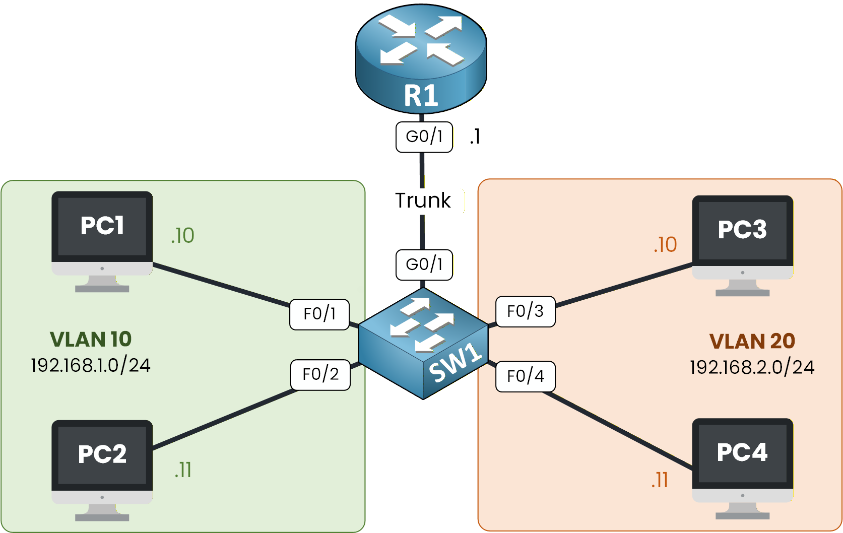
Figure 1 - Router on a Stick Topology
Imagine a company where different departments, such as Sales and Tech need to be able to communicate with each other.
So far in this course, you’ve learned:
How VLANs segment broadcast domains
How trunking carries multiple VLANs over a single link
How default gateways allow traffic to leave a subnet
How routers use subinterfaces to route between VLANs
In this lab, you will put all these concepts together.
We’ll walk through each step to configure Router-on-a-Stick, verify the subinterfaces, set gateways, and test inter-VLAN communication directly in Packet Tracer.How to Begin
Before starting, download the Packet Tracer file using the button at the top of the page.
The topology already includes all PC addressing, so you can focus entirely on VLANs, trunking, subinterfaces, and routing verification.Lab Overview
Here’s the structure we will follow throughout this lab:
Step 1 – Set Up VLANs and Switch Ports
Step 2 – Configure Router Subinterfaces
Step 3 – Set Default Gateways on PCs
Step 4 – Test Inter-VLAN Routing
Let’s Get Started
Open the Packet Tracer file and try configuring the VLANs and switch ports on your own first.
This helps you activate prior knowledge before following the guided solution.In the next sections, we’ll walk through each configuration step together and verify that Router-on-a-Stick is working properly.
Answer the question below
In this first step, you will prepare the switch so that each department is placed in the right VLAN.

Figure 2 - Router on a Stick Topology
Your goal here is simple:
create VLANs
assign the PCs to those VLANs
configure the trunk toward the router
This prepares the entire Layer 2 side before the router can route between VLANs.
Create VLAN 10 and VLAN 20
Start by creating the two VLANs used in this lab.
VLAN 10 will group the Sales PCs, and VLAN 20 will group the Tech PCs.Enter the following commands on SW1:
SW1# conf t Enter configuration commands, one per line. End with CNTL/Z. SW1(config)# vlan 10 SW1(config-vlan)# name Sales SW1(config-vlan)# exit SW1(config)# vlan 20 SW1(config-vlan)# name Tech SW1(config-vlan)# exitAt this stage, the switch knows both VLANs exist, but no ports belong to them yet.
Assign Access Ports
Now, you need to place the correct switch ports into the right VLANs.
Ports F0/1–2 → VLAN 10
Ports F0/3–4 → VLAN 20
This ensures each PC belongs to the correct department.
SW1(config)# int range f0/1-2 SW1(config-if-range)# switchport mode access SW1(config-if-range)# switchport access vlan 10 SW1(config-if-range)# no shut SW1(config-if-range)# exit SW1(config)# int range f0/3-4 SW1(config-if-range)# switchport mode access SW1(config-if-range)# switchport access vlan 20 SW1(config-if-range)# exitYou’ve now created two isolated Layer 2 networks.
Configure the Trunk Toward the Router
Next, you must connect SW1 to the router using a trunk.
This trunk is essential: it allows both VLANs to travel over a single physical link (G0/1) using 802.1Q tags.Without this trunk, the router would never see VLAN 10 or VLAN 20.
SW1(config)# int g0/1 SW1(config-if)# switchport mode trunk SW1(config-if)# switchport trunk allowed vlan 10,20 SW1(config-if)# no shut SW1(config-if)# endYour switch is now ready for Router-on-a-Stick.
In the next step, you’ll configure the router so it can route traffic between your VLANs.
Answer the question below
Which switch port must be configured as a trunk toward the router?
Now that your switch is ready and the trunk is carrying VLAN 10 and VLAN 20, it’s time to prepare the router.
This is the crucial part of Router-on-a-Stick: you will create one logical interface per VLAN, each with its own encapsulation and IP address.
Figure 3 - Router on a Stick Topology
Your router will then act as the default gateway for both VLANs.
Let’s configure it step by step.Enable the Physical Interface
Before creating subinterfaces, make sure the physical interface G0/1 (the one connected to the switch) is up.
R1(config)# int g0/1 R1(config-if)# no shutdown %LINK-5-CHANGED: Interface GigabitEthernet0/1, changed state to up %LINEPROTO-5-UPDOWN: Line protocol on Interface GigabitEthernet0/1, changed state to upIf you don’t see these messages, double-check your trunk cable and switch configuration.
Configure Subinterface for VLAN 10
You will now create the first subinterface: G0/1.10
This interface represents VLAN 10 (Sales) and will use 802.1Q tagging.R1(config)# int g0/1.10 %LINK-5-CHANGED: Interface GigabitEthernet0/1.10, changed state to up %LINEPROTO-5-UPDOWN: Line protocol on Interface GigabitEthernet0/1.10, changed state to up R1(config-subif)# encapsulation ? dot1Q IEEE 802.1Q Virtual LAN R1(config-subif)# encapsulation dot1Q ? <1-4094> IEEE 802.1Q VLAN ID R1(config-subif)# encapsulation dot1Q 10 R1(config-subif)# ip address 192.168.1.1 255.255.255.0 R1(config-subif)# exitThis IP address (192.168.1.1) is the default gateway for all devices in VLAN 10.
Configure Subinterface for VLAN 20
Next, create the second subinterface: G0/1.20
This one will represent VLAN 20 (Tech).R1(config)#int g0/1.20 %LINK-5-CHANGED: Interface GigabitEthernet0/1.20, changed state to up %LINEPROTO-5-UPDOWN: Line protocol on Interface GigabitEthernet0/1.20, changed state to up s R1(config-subif)# encapsulation dot1Q ? R1(config-subif)# encapsulation dot1Q 20 R1(config-subif)# ip address 192.168.2.1 255.255.255.0 R1(config-subif)# exitThis IP address (192.168.2.1) will be used as the default gateway for VLAN 20.
Verify Subinterfaces
Before moving on, always check that your subinterfaces appear correctly in the routing table.
R1# show ip int brief Interface IP-Address OK? Method Status Protocol GigabitEthernet0/0 unassigned YES unset administratively down down GigabitEthernet0/1 unassigned YES unset up up GigabitEthernet0/1.10 192.168.1.1 YES manual up up GigabitEthernet0/1.20 192.168.2.1 YES manual up up GigabitEthernet0/2 unassigned YES unset administratively down down Vlan1 unassigned YES unset administratively down downBoth subinterfaces are up
Both VLAN IPs are correctly assigned
The router is now ready to route between VLANs
In the next step, you’ll configure the PCs so they know which gateway to use.
Answer the question below
Which command links subinterface G0/1.10 to VLAN 10?
For Inter-VLAN Routing to work, every PC must know which gateway to use when sending traffic outside its VLAN.
In this step, you will configure the default gateway directly inside Packet Tracer.Accessing the IP Configuration Menu
To set the IP settings of a PC, click on the PC in Packet Tracer, open the Desktop tab, and select IP Configuration.

Figure 4 - IP Configuration in Packet Tracer
Inside this menu, you can configure the IPv4 address, subnet mask, and default gateway.
The default gateway is particularly important here, as it determines how the PC connects to other networks.Where to Enter the Default Gateway
The 'Default Gateway' field is highlighted in orange.
Enter the IP address of the router subinterface that matches the PC’s VLAN here.

Figure 5 - Setting IP Default Gateway
Since PC1 belongs to VLAN 10, its default gateway must be 192.168.1.1, which is the IP address assigned to subinterface G0/1.10 on router R1.
Repeat for Every PC
Once you’ve configured PC1, repeat the same steps for the rest of the PCs:
PCs in VLAN 10 → Default Gateway: 192.168.1.1
PCs in VLAN 20 → Default Gateway: 192.168.2.1
After confirming that every PC has the correct default gateway, all devices are ready for inter-VLAN communication.
In the last Step we test intervlan routing.Answer the question below
What is the default gateway for PCs in VLAN 20?
Now that your Router-on-a-Stick configuration is complete, it’s time to verify that devices from different VLANs can actually communicate with each other.
Testing Connectivity from PC1 to PC3
From PC1 (VLAN 10), open the Command Prompt and try to reach PC3 (VLAN 20) using its IP address: 192.168.2.10.
C:\> ping 192.168.2.10 Pinging 192.168.2.10 with 32 bytes of data: Request timed out. Reply from 192.168.2.10: bytes=32 time<1ms TTL=127 Reply from 192.168.2.10: bytes=32 time<1ms TTL=127 Reply from 192.168.2.10: bytes=32 time<1ms TTL=127 Ping statistics for 192.168.2.10: Packets: Sent = 4, Received = 3, Lost = 1 (25% loss), Approximate round trip times in milli-seconds: Minimum = 0ms, Maximum = 0ms, Average = 0msWhy the First Ping Fails
The very first ping usually fails.
This is normal because PC1 must complete the ARP process before sending IP packets:PC1 must discover the MAC address of its default gateway (R1).
The router must process and route the traffic to VLAN 20.
The return ARP resolution from PC3 must also occur.
Once ARP is complete, the communication succeeds immediately.
Understanding the Inter-VLAN Routing Process
To help you visualize what just happened, look at the diagram below.
It shows the full path a packet takes when travelling from one VLAN to another through the router.
Figure 6 - Router on a Stick Process
Let's go to the entire process together:
PC1 wants to reach 192.168.2.10, which is outside its subnet.
It sends the packet to its default gateway 192.168.1.1 on the router (subinterface G0/1.10).
This frame is untagged because it comes from an access port.SW1 receives the untagged frame on an access port in VLAN 10.
It adds the 802.1Q VLAN tag 10 and forwards the frame on the trunk link toward the router.The router receives the tagged frame.
The VLAN 10 tag matches subinterface G0/1.10, so the router processes it there.
The router checks the destination IP 192.168.2.10 and sees that it belongs to the network handled by G0/1.20.The router sends the packet back to SW1 using subinterface G0/1.20.
It adds VLAN tag 20 on the outgoing frame, because the packet belongs to VLAN 20.SW1 receives the frame with VLAN tag 20 on the trunk.
It removes the tag before sending the frame out of the access port toward PC3.
Now, let's conclude with the summary step.
Answer the question below
Which device performs the routing between VLAN 10 and VLAN 20 in this test?
Congratulations, you have completed the Router-on-a-Stick Lab!
This lab is a key milestone in your CCNA journey because it shows how a router can enable communication between VLANs using 802.1Q subinterfaces.Here are the commands I want you to remember to configure Router-on-a-Stick:
Key Commands for Router-on-a-Stick
R1(config)# int g0/1.10 → creates the subinterface for VLAN 10 R1(config-subif)# encapsulation dot1Q 10 → applies 802.1Q tagging for VLAN 10 R1(config-subif)# ip address 192.168.1.1 255.255.255.0 → defines the IP address for the VLAN gateway R1(config-subif)# exitYou are now ready to continue with the next lesson on SVI Inter-VLAN Routing, where you will learn the modern way to route between VLANs using multilayer switches.
Let’s continue together with the SVI lesson.
Answer the question below