In this lab, you'll learn how to configure Network Time Protocol (NTP) so your devices can keep accurate and synchronized time. Clock synchronization is essential in networking because logs, monitoring tools, and security features depend on precise timestamps.
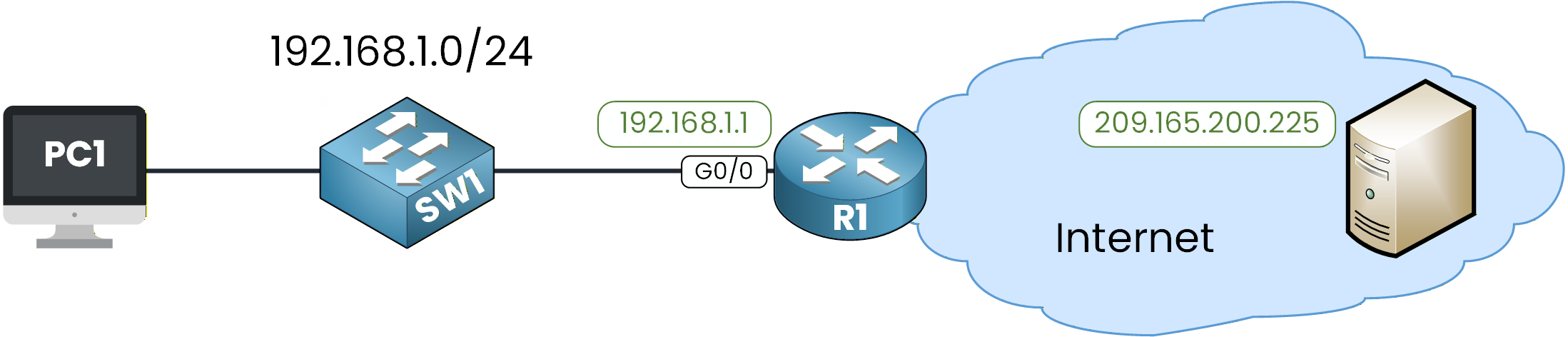
Figure 1 - NTP Lab Configuration Topology
This lab will guide you through configuring and verifying NTP.
You’ll see how a router learns time from an external server and then provides synchronized time to a switch.How to Begin
Before starting, download the lab file using the button at the top of the page.
The IP addressing/Routing is already configured in the topology, so you can focus entirely on the NTP configuration.Lab Overview
In this lab, you will complete the following tasks:
Step 1 – Verify Initial Clock and Connectivity
Step 2 – Configure Timezone and Manual Clock
Step 3 – Configure SW1 as an NTP Client
Step 4 – Configure R1 to Sync with an External NTP Server
Step 5 – Verify NTP Client Synchronization on SW1
Step 6 – Convert R1 into an NTP Master
Let’s Get Started
Open the Packet Tracer file and try to complete the tasks on your own.
Each step is designed to guide you through the process, and if you get stuck, the explanations below will help you understand exactly what to do.Let’s go!
Answer the question below
First, let’s check whether R1 can reach the external NTP server on the internet.
We can use the ping command:R1# ping 209.165.200.225 Type escape sequence to abort. Sending 5, 100-byte ICMP Echos to 209.165.200.225, timeout is 2 seconds: !!!!! Success rate is 100 percent (5/5), round-trip min/avg/max = 0/0/1 msGreat, communication is working.
This confirms that R1 has IP reachability to the public NTP server, which is required before it can synchronize its clock using NTP.Check the Initial NTP State
Now let’s look at the NTP status on R1:
R1# show ntp status
%NTP is not enabled.
NTP is disabled by default on Cisco devices.
It only starts running after you configure an NTP server or enable NTP master, so this output is completely normal at this stage.
Let’s check SW1 as well:SW1# show ntp status %NTP is not enabled.The same result was expected since we haven’t configured NTP yet.
Check the Device Clocks
Now let’s take a look at the device clocks. Here is the output on SW1:
SW1# show clock detail
*0:1:54.990 UTC Mon Mar 1 1993
Time source is hardware calendar
And on R1:
R1# show clock detail
*0:1:48.709 UTC Mon Mar 1 1993
Time source is hardware calendar
You can see that:
The date is incorrect (1993), which is normal when no valid time source is available.
The line Time source is hardware calendar indicates that the device is simply using its internal clock.
In the next step, we’ll set the timezone and manually adjust the clock so both devices start from a consistent time before configuring NTP.
Let’s continue!
Answer the question below
What is the current time source?
Before using NTP, let’s see how to configure the local time manually on a Cisco device.
This helps you understand how the clock works before we automate everything with NTP.Set the Timezone
R1# conf t
Enter configuration commands, one per line.  End with CNTL/Z.
R1(config)# clock timezone UTC 0
R1(config)# exit
We set the router to UTC with an offset of 0.
Set the Local Clock
Now let’s manually configure the date and time on R1:
R1# clock set 10:52:00 13 December 2025Verify:
R1# show clock detail
10:52:3.63 UTC Sat Dec 13 2025
Time source is user configuration
The clock is now correctly set, and the device shows Time source is user configuration, meaning the time was set manually.
Now apply the same configuration on SW1:
SW1# conf t
Enter configuration commands, one per line.  End with CNTL/Z.
SW1(config)# clock timezone UTC 0
SW1(config)# exit
SW1# clock set 10:52:10 13 December 2025
And verify:
SW1# show clock detail
10:52:2.131 UTC Sat Dec 13 2025
Time source is user configuration
Both devices now have a consistent manual clock.
Manually configuring time is useful for labs, but in real networks clocks drift over time.
This is exactly why NTP is needed.Let’s continue and start configuring NTP.
Answer the question below
What is the time source now?
Here is the NTP hierarchy we will configure in this lab:
SW1 gets its time from R1, and R1 gets its time from the public NTP server.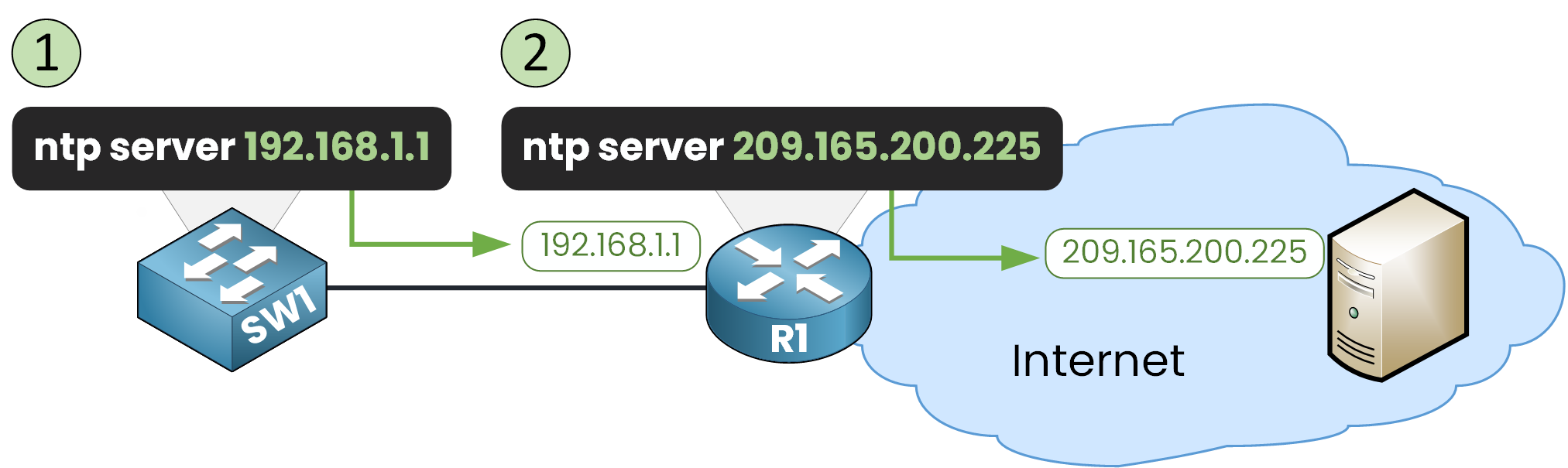
Figure 2 - NTP Configuration Steps
40 % Complete: you’re making great progress
Unlock the rest of this lesson
If you’d like to continue your CCNA journey, simply create your free account.
Access all CCNA lessons
Practice with hands-on labs
Train with Practice exams and Quizzes
Progress tracking in your dashboard
Made by network engineers - CCNP certified
learners globally