In this lab, you will learn how to configure HSRP (Hot Standby Router Protocol) on two routers to provide a redundant default gateway for your network.
HSRP is an important CCNA topic because it ensures that end devices stay connected even if one router becomes unavailable.
Figure 1 – HSRP Configuration Lab Topology
Your objective is to set up the HSRP group, verify the Active and Standby roles, update the PCs so they use the virtual gateway, test the failover process, and confirm that preemption restores the main router as Active when it comes back online.
We'll walk through everything step by step so you can understand both the configuration and how HSRP behaves in a real scenario.
Lab Overview
Here’s the structure we’ll follow throughout this lab:
Step 1 – Initial Connectivity
Step 2 – Configure HSRP on R1 and R2
Step 3 – Configure PCs with the virtual gateway
Step 4 – Test HSRP failover
Step 5 – Restore R1 and verify preemption
Let’s Get Started
Begin with Step 1 to verify the initial connectivity. Then follow each step carefully to configure, test, and fully understand how HSRP works.
Answer the question below
Click 'Complete' to continue
Let’s begin by looking at our topology.
We have the LAN network 192.168.10.0/24 connected to two routers.
In this step, we will use PC1 to check if it can reach the external destination 8.8.8.8.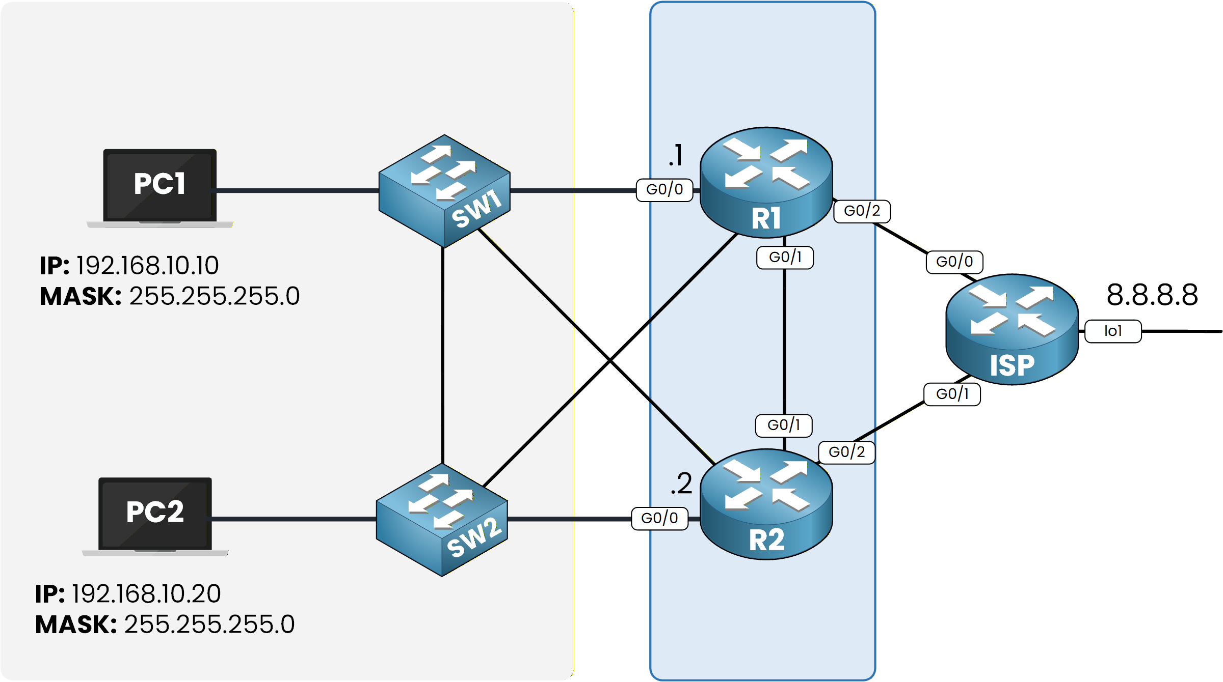
Figure 2 – HSRP Topology
The 8.8.8.8 address is simulated by a loopback interface on the ISP router.
First, open the command prompt on PC1.We can now test basic connectivity by sending a ping to 8.8.8.8:
C:\> ping 8.8.8.8

Pinging 8.8.8.8 with 32 bytes of data:

Reply from 8.8.8.8: bytes=32 time<1ms TTL=254
Reply from 8.8.8.8: bytes=32 time<1ms TTL=254
Reply from 8.8.8.8: bytes=32 time<1ms TTL=254
Reply from 8.8.8.8: bytes=32 time<1ms TTL=254

Ping statistics for 8.8.8.8:
    Packets: Sent = 4, Received = 4, Lost = 0 (0% loss),
Approximate round trip times in milli-seconds:
    Minimum = 0ms, Maximum = 0ms, Average = 0ms
The ping succeeds, which means PC1 can already reach the external network through its current gateway.
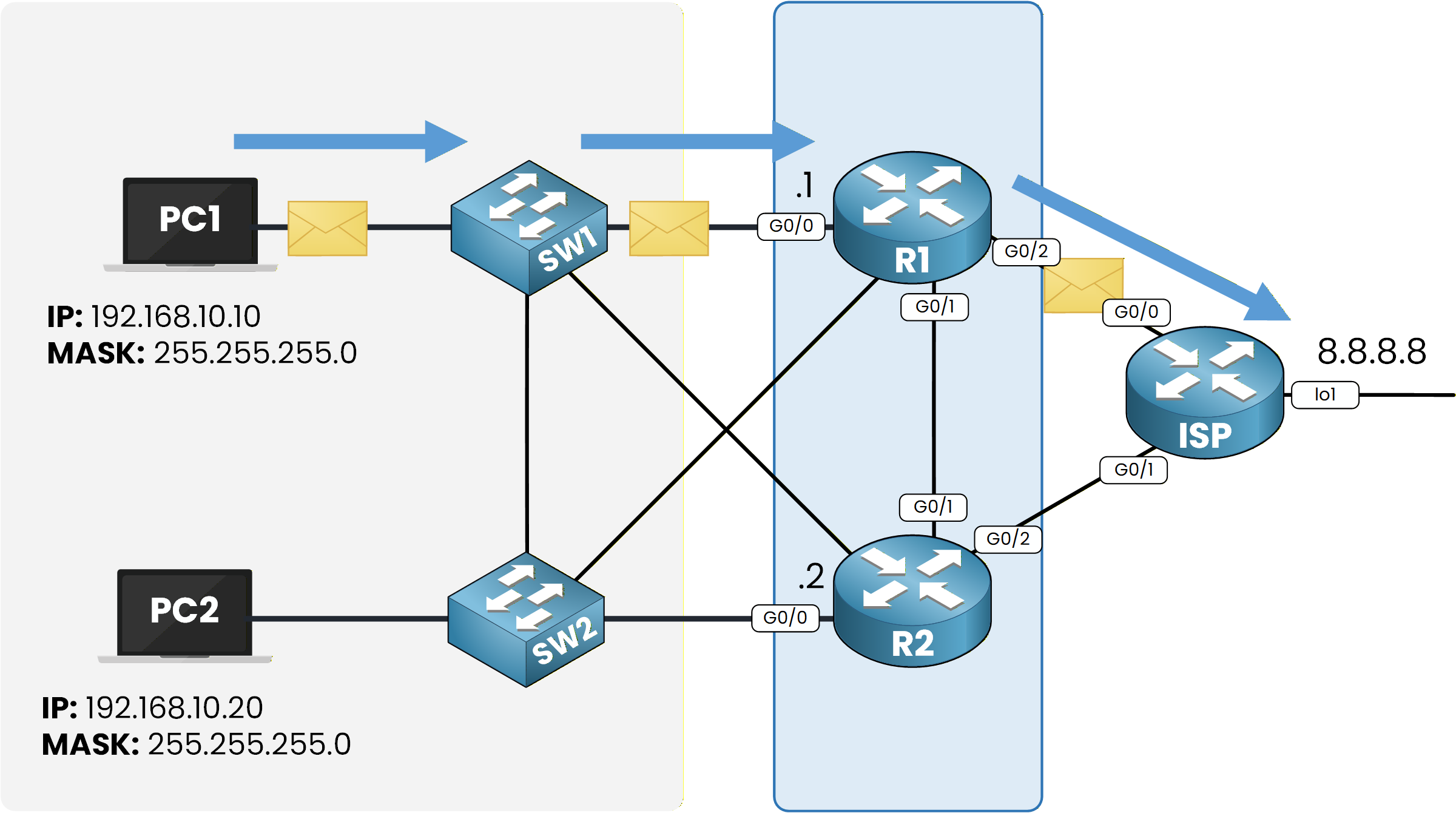
Figure 3 – Initial HSRP topology overview
Next, let’s check which gateway PC1 is using.
Run the following command:C:\> ipconfig FastEthernet0 Connection:(default port) Connection-specific DNS Suffix..: Link-local IPv6 Address.........: FE80::202:16FF:FE48:B8C9 IPv6 Address....................: :: IPv4 Address....................: 192.168.10.10 Subnet Mask.....................: 255.255.255.0 Default Gateway.................: :: 192.168.10.1We can see that the default gateway is 192.168.10.1, which belongs to R1.
To confirm the path taken by packets, use:
C:\> tracert 8.8.8.8

Tracing route to 8.8.8.8 over a maximum of 30 hops:

  1   0 ms      0 ms      0 ms      192.168.10.1
  2   0 ms      0 ms      0 ms      8.8.8.8

Trace complete.
The first hop is 192.168.10.1, confirming that R1 is currently acting as the gateway.
Everything looks good.
In the next step, we will configure HSRP on R1 and R2 to provide a redundant default gateway.Answer the question below
Which router is the current gateway?
In this step, we will configure HSRP on both routers so they can share a single virtual default gateway.
We’ll start with R1, then apply the same logic on R2.On R1, go to the interface facing the LAN, which is GigabitEthernet0/0.
We enable HSRP version 2 using thestandby version 2command.R1# conf t Enter configuration commands, one per line. End with CNTL/Z. R1(config)# int g0/0 R1(config-if)# standby version 2 R1(config-if)# standby ? <0-4095> group number ip Enable HSRP and set the virtual IP address ipv6 Enable HSRP IPv6 preempt Overthrow lower priority Active routers priority Priority level timers Hello and hold timers track Priority Tracking version HSRP versionHere, you can see all options available for the
standby ?command.
Now we configure the virtual IP address, set the priority to 110, and enable preemption so R1 becomes the Active router.R1(config-if)# standby 1 ip 192.168.10.3 R1(config-if)# standby 1 priority 110 R1(config-if)# standby 1 preempt %HSRP-6-STATECHANGE: GigabitEthernet0/0 Grp 1 state Init -> Init %HSRP-6-STATECHANGE: GigabitEthernet0/0 Grp 1 state Speak -> Standby %HSRP-6-STATECHANGE: GigabitEthernet0/0 Grp 1 state Standby -> Active R1(config-if)# end R1# write memoryAfter enabling preemption on R1, we now configure HSRP on R2.
The process is the same, but this time we set a lower priority (90) so R2 becomes the Standby router.R2# conf t Enter configuration commands, one per line. End with CNTL/Z. R2(config)# int g0/0 R2(config-if)# standby version 2 R2(config-if)# standby 1 priority 90 R2(config-if)# standby 1 ip 192.168.10.3 R2(config-if)# standby 1 preempt R2(config-if)# end R2# write memoryAt this point, both routers are part of HSRP Group 1.
Let’s verify the configuration.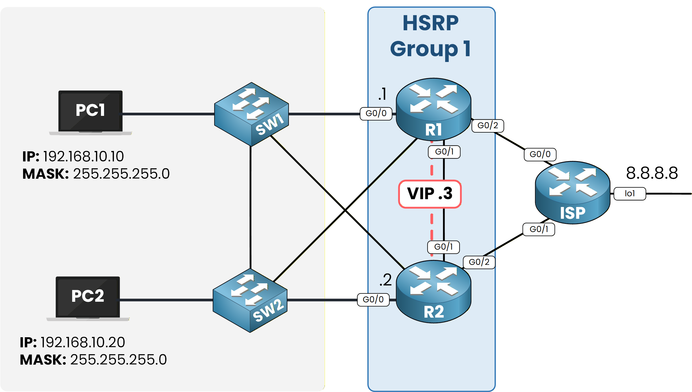
Figure 4 – HSRP Group 1 configuration overview
The
show standbycommand is very useful because it allows us to see the state of each HSRP group in detail.
Let’s check the configuration on R1:R1# show standby GigabitEthernet0/0 - Group 1 (version 2) State is Active 5 state changes, last state change 00:06:08 Virtual IP address is 192.168.10.3 Active virtual MAC address is 0000.0C9F.F001 Local virtual MAC address is 0000.0C9F.F001 (v2 default) Hello time 3 sec, hold time 10 sec Next hello sent in 1.979 secs Preemption enabled Active router is local Standby router is 192.168.10.2, priority 90 (expires in 6 sec) Priority 110 (configured 110) Group name is hsrp-Gig0/0-1 (default)Here, R1 clearly shows itself as the Active router, with R2 as the Standby router.
We can also see the configured priority value that determines the election result.Now let’s look at R2’s point of view:
R2# show standby
GigabitEthernet0/0 - Group 1 (version 2)
  State is Standby
    12 state changes, last state change 00:06:22
  Virtual IP address is 192.168.10.3
  Active virtual MAC address is 0000.0C9F.F001
    Local virtual MAC address is 0000.0C9F.F001 (v2 default)
  Hello time 3 sec, hold time 10 sec
    Next hello sent in 2.243 secs
  Preemption enabled
  Active router is 192.168.10.1, priority 110 (expires in 9 sec)
    MAC address is 0000.0C9F.F001
  Standby router is local
  Priority 90 (configured 90)
  Group name is hsrp-Gig0/0-1 (default)
Each router displays its own perspective, which is normal with HSRP.
R1 is Active, R2 is Standby, and both agree on the virtual IP and virtual MAC address.Now that the HSRP group is fully configured and working, the next step is to update the default gateway on the PCs so they use the virtual IP address of the group.
Answer the question below
What is R1’s priority?
Now that the HSRP group is running, we need to update the default gateway on PC1 and PC2 to the HSRP virtual IP: 192.168.10.3.
Once both PCs use the virtual gateway, all traffic that needs to leave the LAN will go through the Active router of the HSRP group.
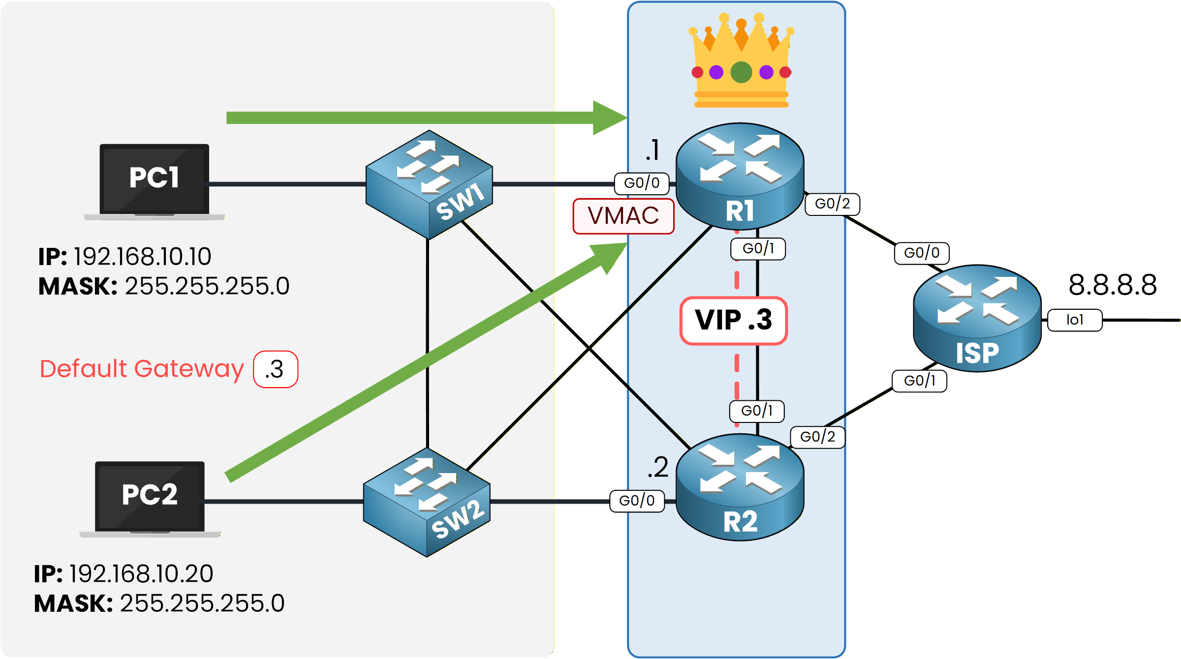
Figure 5 – Active router using VMAC
Let’s verify this on PC1 by sending a ping to the external destination:
C:\> ping 8.8.8.8

Pinging 8.8.8.8 with 32 bytes of data:

Reply from 8.8.8.8: bytes=32 time=1ms TTL=254
Reply from 8.8.8.8: bytes=32 time=17ms TTL=254
Reply from 8.8.8.8: bytes=32 time<1ms TTL=254
Reply from 8.8.8.8: bytes=32 time<1ms TTL=254

Ping statistics for 8.8.8.8:
    Packets: Sent = 4, Received = 4, Lost = 0 (0% loss),
Approximate round trip times in milli-seconds:
    Minimum = 0ms, Maximum = 17ms, Average = 4ms
The ping succeeds.
Now let’s look at the ARP table on PC1 to confirm that it is using the HSRP virtual MAC address:C:\> arp -a Internet Address Physical Address Type 192.168.10.1 0004.9a93.a122 dynamic 192.168.10.3 0000.0c9f.f001 dynamicHere you can see the virtual IP address 192.168.10.3 mapped to the HSRP virtual MAC address.
This confirms that the PC is now using the virtual gateway.Next, let’s check the path taken to reach 8.8.8.8:
C:\> tracert 8.8.8.8

Tracing route to 8.8.8.8 over a maximum of 30 hops:

  1   0 ms      0 ms      0 ms      192.168.10.1
  2   0 ms      1 ms      0 ms      8.8.8.8

Trace complete.
The first hop is 192.168.10.1, which is the physical IP of R1.
Thanks to HSRP, PC1 now uses the Active router to forward traffic toward external destinations.Answer the question below
Which gateway must the PCs use?
Now that HSRP is configured and working, let’s test how the network reacts when the Active router fails.
Once R1 is turned off, it stops sending HSRP hello messages.
HSRP detects this change and automatically promotes R2 to the Active role.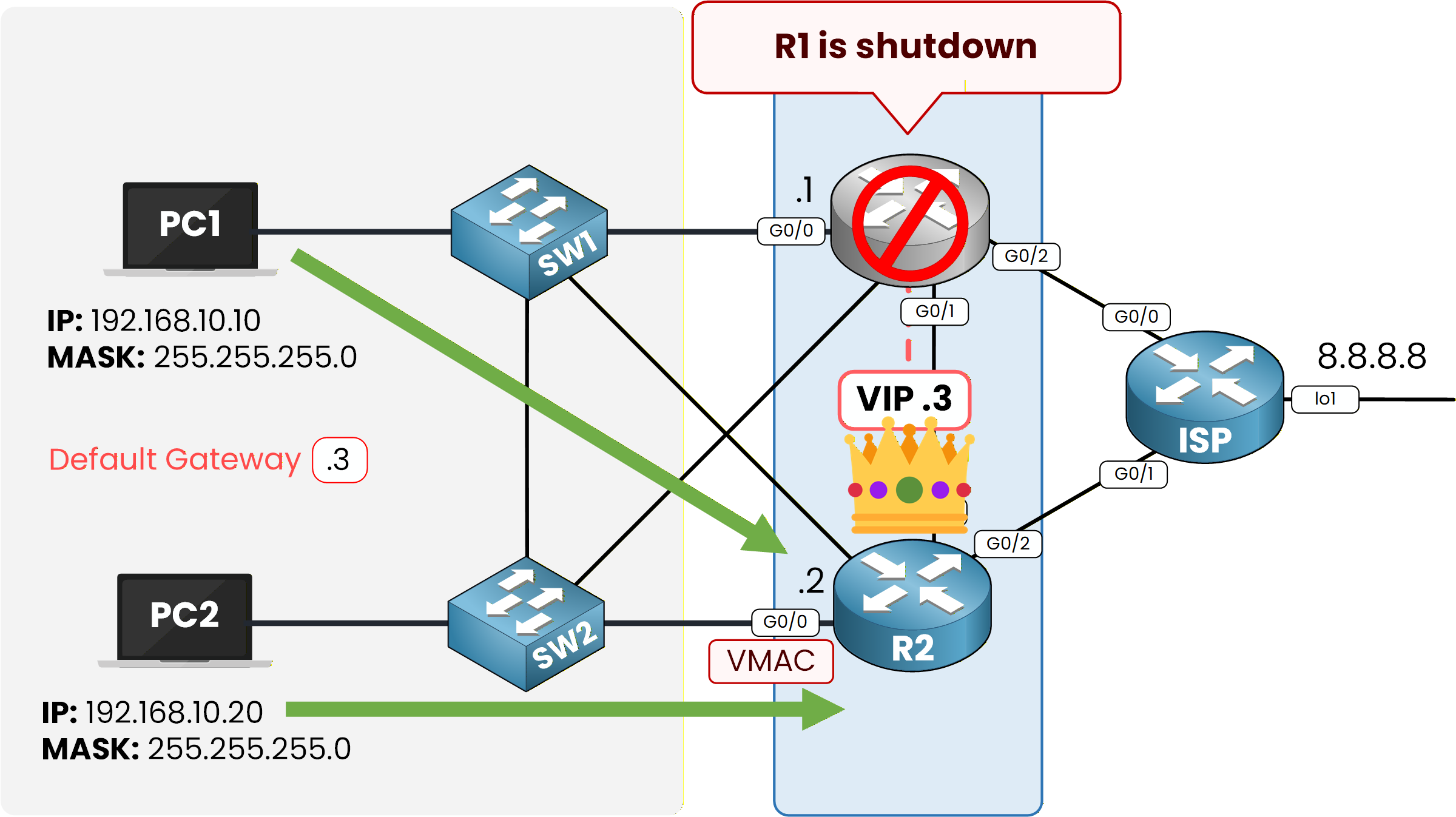
Figure 6 – Failover to R2 after R1 shutdown
As a result, end devices now use R2 as their default gateway.
This is a good moment to notice how seamless this is for users in a real network.
Even if a router goes down, traffic keeps flowing through the backup router.
That’s exactly why HSRP exists.Let’s check if everything is still working by sending a ping from PC1:
C:\> ping 8.8.8.8

Pinging 8.8.8.8 with 32 bytes of data:

Reply from 8.8.8.8: bytes=32 time<1ms TTL=254
Reply from 8.8.8.8: bytes=32 time=1ms TTL=254
Reply from 8.8.8.8: bytes=32 time<1ms TTL=254
Reply from 8.8.8.8: bytes=32 time<1ms TTL=254

Ping statistics for 8.8.8.8:
    Packets: Sent = 4, Received = 4, Lost = 0 (0% loss),
Approximate round trip times in milli-seconds:
    Minimum = 0ms, Maximum = 1ms, Average = 0ms
The ping succeeds.
Now let’s check the new path using tracert:C:\> tracert 8.8.8.8 Tracing route to 8.8.8.8 over a maximum of 30 hops: 1 0 ms 0 ms 0 ms 192.168.10.2 2 0 ms 0 ms 0 ms 8.8.8.8 Trace complete.We can clearly see that PC1 now uses 192.168.10.2, the physical IP of R2.
Finally, let’s check the updated ARP table:
C:\> arp -a
  Internet Address      Physical Address      Type
  192.168.10.2          0090.21e6.35ce        dynamic
  192.168.10.3          0000.0c9f.f001        dynamic
PC1 has learned the MAC address of R2 for 192.168.10.2, while still keeping the virtual MAC for the HSRP group.
We can now move on to the next section and restore R1.
Answer the question below
Which IP appears as the first hop after failover?
Now let’s power R1 back on.
Remember what preemption does:
if a router has a higher priority, it can take back the Active role as soon as it comes online.In our case:
R1: Priority 110
R2: Priority 90
So when R1 boots up, it should automatically become Active again.
Here is the log that confirms it:
%HSRP-6-STATECHANGE: GigabitEthernet0/0 Grp 1 state Init -> Init
%HSRP-6-STATECHANGE: GigabitEthernet0/0 Grp 1 state Standby -> Active
This shows that R1 has taken back the Active role.
Let’s test connectivity again to make sure everything works:
C:\> ping 8.8.8.8

Pinging 8.8.8.8 with 32 bytes of data:

Reply from 8.8.8.8: bytes=32 time<1ms TTL=254
Reply from 8.8.8.8: bytes=32 time<1ms TTL=254
Reply from 8.8.8.8: bytes=32 time<1ms TTL=254
Reply from 8.8.8.8: bytes=32 time<1ms TTL=254

Ping statistics for 8.8.8.8:
    Packets: Sent = 4, Received = 4, Lost = 0 (0% loss),
Approximate round trip times in milli-seconds:
    Minimum = 0ms, Maximum = 0ms, Average = 0ms
Everything is working correctly, and both PC1 and PC2 now use R1 again as the Active router.
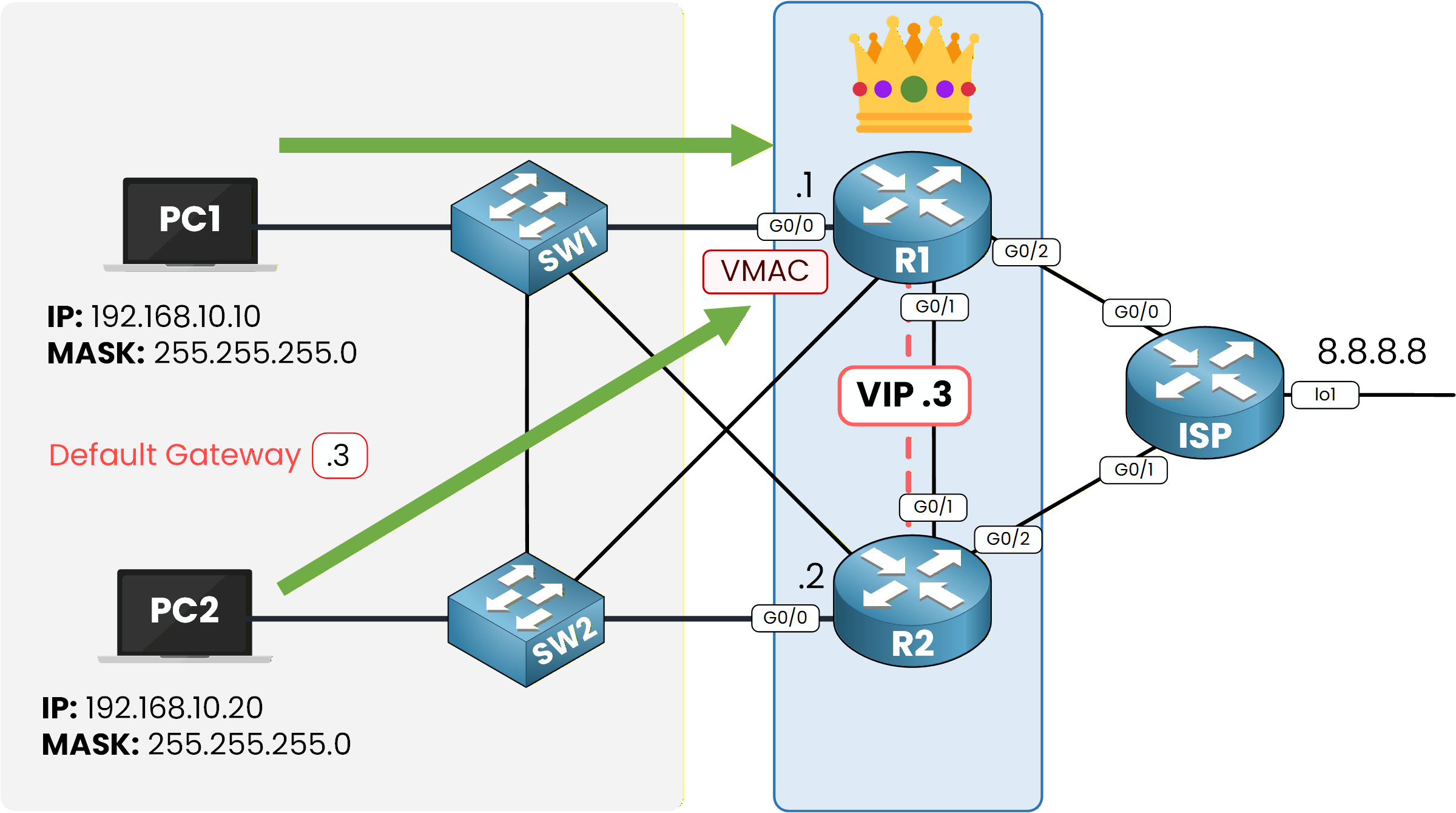
Figure 7 – R1 regains active role after recovery
Users would not notice any of these changes in a real network.
HSRP keeps the gateway available at all times.Let’s confirm that R1 is used again by checking the path:
C:\> tracert 8.8.8.8

Tracing route to 8.8.8.8 over a maximum of 30 hops:

  1   0 ms      0 ms      0 ms      192.168.10.1
  2   0 ms      0 ms      0 ms      8.8.8.8

Trace complete.
And the updated ARP table:
C:\> arp -a
  Internet Address      Physical Address      Type
  192.168.10.1          0004.9a93.a122        dynamic
  192.168.10.2          0090.21e6.35ce        dynamic
  192.168.10.3          0000.0c9f.f001        dynamic
The ARP entries now show the physical MAC of R1 again, along with the virtual MAC of the HSRP group.
Answer the question below
Why does R1 become Active again?
Let’s wrap up.
In this lab, you applied HSRP in a real network topology and saw how it provides gateway redundancy.
You configured HSRP on both routers, tested a failover, restored the Active router, and observed how the network reacted at each step.Take some time to practice HSRP on your own.
You can build different topologies and repeat the configuration.
What matters most is understanding how to set up HSRP and how it behaves when a router fails.
Good job completing the lab!Answer the question below
What process did you test in Step 4 when R1 went down?