In this lab, you'll learn to set up Dynamic NAT (Network Address Translation) on a router. This allows internal devices to share a pool of public IP addresses when they connect to external networks.
Dynamic NAT is a crucial topic for CCNA. It enables several inside hosts to use a pool of public IPs. This setup avoids the need for a fixed one-to-one mapping.
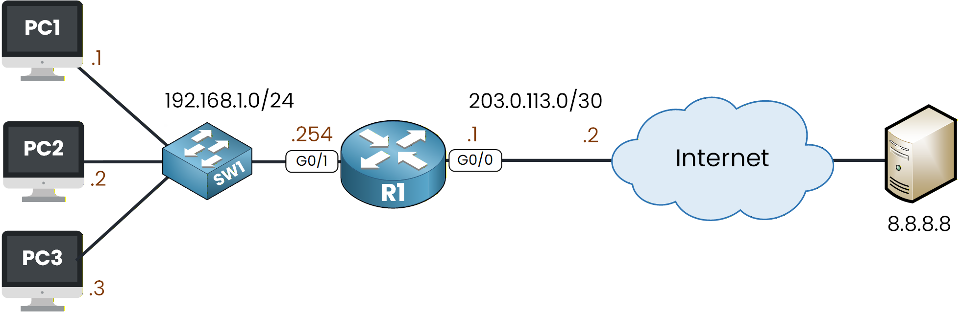
Figure 1 - Dynamic NAT Configuration Lab
This lab will help you configure, verify, and test Dynamic NAT. You'll gain a clear understanding of how the translation process works.
How to Begin
The topology above is already set up for you with all IP addressing in place.
You can focus entirely on the Dynamic NAT configuration and run every command directly in the integrated CLI below.Lab Overview
Here’s the structure we will follow throughout this lab:
Step 1 – Configure Dynamic NAT
Step 2 – Test Dynamic NAT Behavior
Step 3 – Observe and Reset the NAT TranslationsLet’s get started!
Answer the question below
Click 'Complete' to continue
The first thing we need to do when configuring Dynamic NAT is to define the inside and outside interfaces.
In your network topology, this is very simple:Interface G0/1 is connected to the inside network.
Interface G0/0 is connected to the outside network.
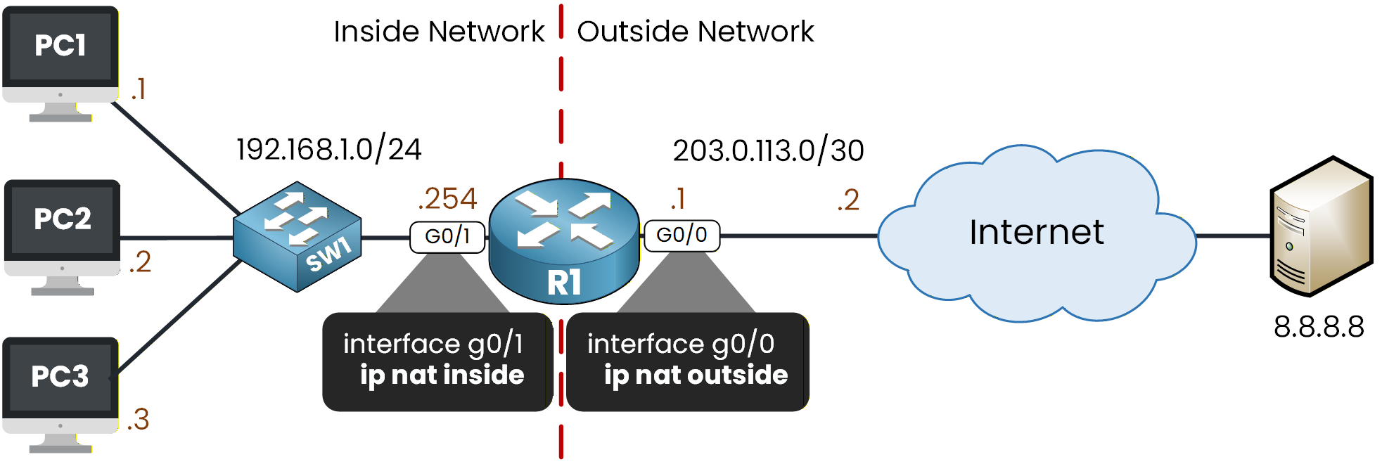
Figure 2 - NAT Inside and NAT Outside Commands
In Figure 2, we set ip nat inside and ip nat outside. This allows NAT to identify the boundary between the internal and external networks.
Configure NAT Roles on the Interfaces
From global configuration mode, apply the following commands:
R1# conf t
Enter configuration commands, one per line.  End with CNTL/Z.
R1(config)# interface g0/1
R1(config-if)# ip nat inside
R1(config-if)# exit

R1(config)# interface g0/0
R1(config-if)# ip nat outside
R1(config-if)# exit
Now that the NAT roles are configured, this is the moment to start the Dynamic NAT setup.
Dynamic NAT allows you to create a pool of public addresses that internal hosts can use when they need to reach external networks.
Before we create the pool, we must first identify which inside hosts are allowed to use it.To do that, we use a standard ACL, a simple filter that matches source addresses (ACLs get their own module later in this path). In our case, we want devices in the 192.168.1.0/24 network to be able to use the NAT pool.
Define the Inside Addresses Using an ACL
Let’s create a standard ACL named LOCAL_HOSTS:
R1(config)# ip access-list standard LOCAL_HOSTS
R1(config-std-nacl)# permit 192.168.1.0 0.0.0.255
R1(config-std-nacl)# exit
With the ACL created, we can now configure the NAT pool.
Create the Dynamic NAT Pool
The command used to create a NAT pool offers several options, so let’s walk through them together:
R1(config)# ip nat ?
  inside   Inside address translation
  outside  Outside address translation
  pool     Define pool of addresses

R1(config)# ip nat pool ?
  WORD  Pool name
First, we need to give a name to the NAT pool. In this example, we will use PUBLIC_POOL.
Then we must specify the first IP address of the pool, the last IP address, and finally the subnet mask.
In this lab, we will use a small range of public addresses from the 50.0.0.0/24 network.R1(config)# ip nat pool PUBLIC_POOL ? A.B.C.D Start IP address R1(config)# ip nat pool PUBLIC_POOL 50.0.0.1 ? A.B.C.D End IP address R1(config)# ip nat pool PUBLIC_POOL 50.0.0.1 50.0.0.3 ? netmask Specify the network mask R1(config)# ip nat pool PUBLIC_POOL 50.0.0.1 50.0.0.3 netmask ? A.B.C.D Network mask R1(config)# ip nat pool PUBLIC_POOL 50.0.0.1 50.0.0.3 netmask 255.255.255.0You might notice that these addresses are not in the same subnet as the outside interface (203.0.113.0/30). That's perfectly normal. In practice, your ISP assigns you a separate block of public IPs specifically for NAT, and their router already has a route pointing that block back to yours.
Now that the ACL shows which inside hosts can use Dynamic NAT, we need to connect it to the NAT pool.
This way, the router knows which devices can access the public addresses.Link the ACL to the Pool
To do this, we start by exploring the available options under the
ip nat inside sourcecommand:R1(config)# ip nat inside ? source Source address translation R1(config)# ip nat inside source ? list Specify access list describing local addresses static Specify static local->global mappingWe select a list to attach our ACL, specify LOCAL_HOSTS, and then choose a pool to reference our NAT pool.
R1(config)# ip nat inside source list ?
  <1-199>  Access list number for local addresses
  WORD     Access list name for local addresses

R1(config)# ip nat inside source list LOCAL_HOSTS ?
  interface  Specify interface for global address
  pool       Name pool of global addresses

R1(config)# ip nat inside source list LOCAL_HOSTS pool PUBLIC_POOL
R1(config)# exit
And with that, the Dynamic NAT configuration is complete.
Dynamic NAT Configuration Summary
The figure below summarizes the four main parts of the Dynamic NAT configuration.
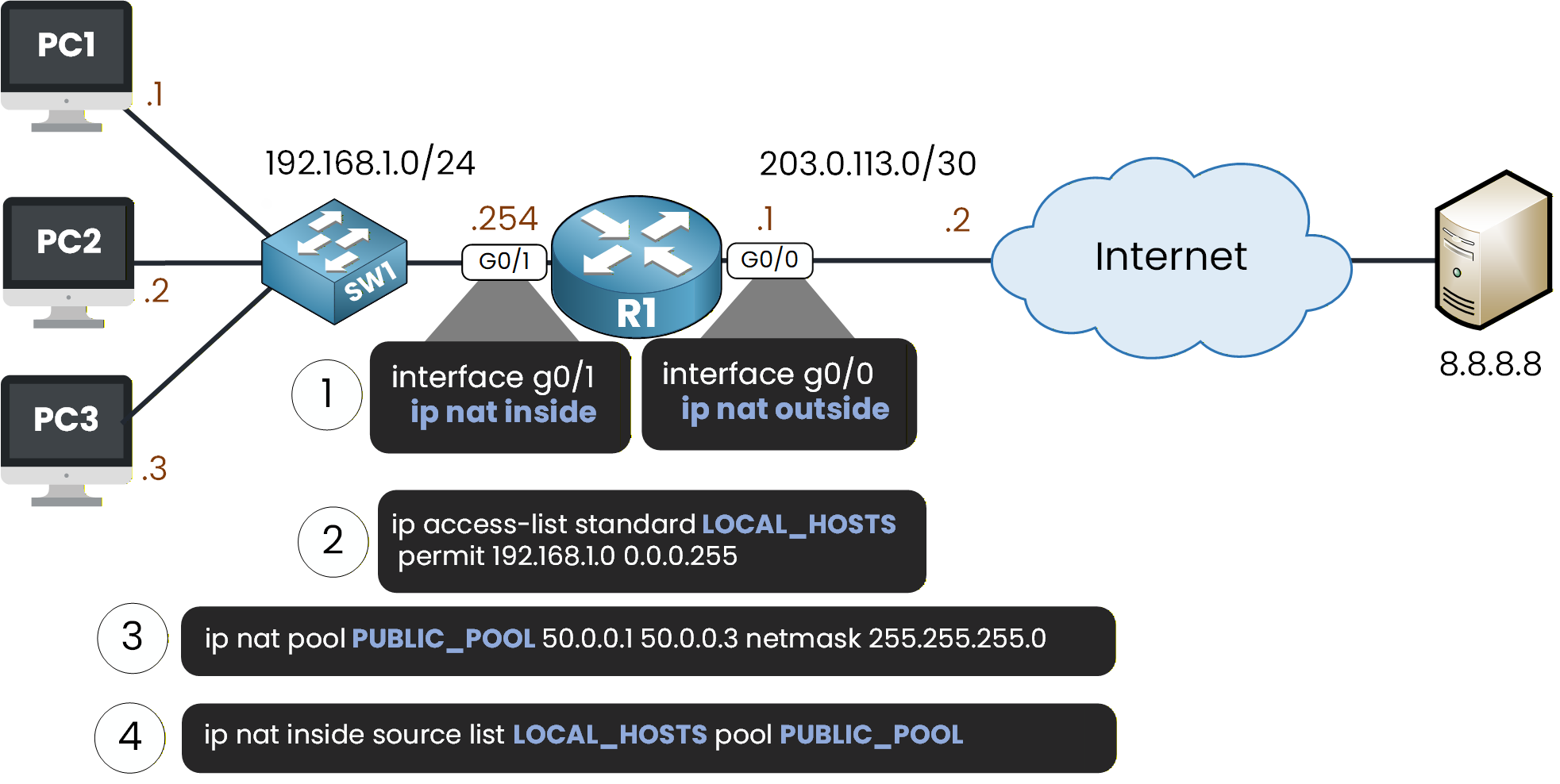
Figure 3 - Dynamic NAT Full Configuration
The ACL determines which inside hosts can use the NAT pool. The final command links the ACL to the pool, enabling those hosts to temporarily use a public IP address.
Now, let’s see whether the PCs can successfully send a ping to the external server at 8.8.8.8.
Answer the question below
Which object defines which inside hosts are allowed to use the NAT pool?
If we start from PC1 and send a ping to 8.8.8.8:
C:\> ping 8.8.8.8

Pinging 8.8.8.8 with 32 bytes of data:

Request timed out.
Request timed out.
Reply from 8.8.8.8: bytes=32 time<1ms TTL=126
Reply from 8.8.8.8: bytes=32 time<1ms TTL=126

Ping statistics for 8.8.8.8:
    Packets: Sent = 4, Received = 2, Lost = 2 (50% loss),
Approximate round trip times in milli-seconds:
    Minimum = 0ms, Maximum = 0ms, Average = 0ms
The first two ping attempts time out.
This is expected: R1 must first learn the MAC address of its next-hop router using ARP.
Once the ARP resolution is complete, the traffic flows normally, and Dynamic NAT takes place correctly.Now let’s test from PC2:
C:\> ping 8.8.8.8

Pinging 8.8.8.8 with 32 bytes of data:

Reply from 8.8.8.8: bytes=32 time<1ms TTL=126
Reply from 8.8.8.8: bytes=32 time=44ms TTL=126
Reply from 8.8.8.8: bytes=32 time=2ms TTL=126
Reply from 8.8.8.8: bytes=32 time<1ms TTL=126

Ping statistics for 8.8.8.8:
    Packets: Sent = 4, Received = 4, Lost = 0 (0% loss),
Approximate round trip times in milli-seconds:
    Minimum = 0ms, Maximum = 44ms, Average = 11ms
Here, all pings succeed.
Dynamic NAT is working properly, and PC2 also receives a public IP address from the NAT pool.Finally, let’s test from PC3:
C:\> ping 8.8.8.8

Pinging 8.8.8.8 with 32 bytes of data:

Reply from 8.8.8.8: bytes=32 time<1ms TTL=126
Reply from 8.8.8.8: bytes=32 time=44ms TTL=126
Reply from 8.8.8.8: bytes=32 time=2ms TTL=126
Reply from 8.8.8.8: bytes=32 time<1ms TTL=126

Ping statistics for 8.8.8.8:
    Packets: Sent = 4, Received = 4, Lost = 0 (0% loss),
Approximate round trip times in milli-seconds:
    Minimum = 0ms, Maximum = 44ms, Average = 11ms
Again, the communication is successful.
Each PC is now using one of the available public IP addresses from the Dynamic NAT pool.In the next step, we will examine the NAT table and look at the translations created by these tests.
Answer the question below
Why do the first ping attempts from PC1 fail?
Let’s look at the NAT translations that were created on R1 after the pings from the three PCs.
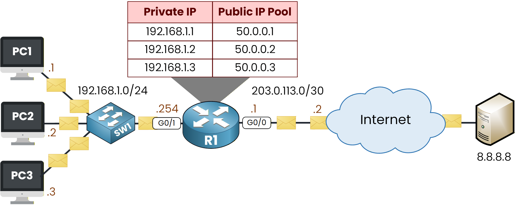
Figure 4 - Dynamic NAT Translations in Progress
Display the Active Translations
To see the active translation, enter the following command:
R1# show ip nat translations
Pro  Inside global     Inside local       Outside local      Outside global
icmp 50.0.0.1:1        192.168.1.1:1      8.8.8.8:1          8.8.8.8:1
icmp 50.0.0.1:2        192.168.1.1:2      8.8.8.8:2          8.8.8.8:2
icmp 50.0.0.1:3        192.168.1.1:3      8.8.8.8:3          8.8.8.8:3
icmp 50.0.0.1:4        192.168.1.1:4      8.8.8.8:4          8.8.8.8:4
icmp 50.0.0.2:1        192.168.1.2:1      8.8.8.8:1          8.8.8.8:1
icmp 50.0.0.2:2        192.168.1.2:2      8.8.8.8:2          8.8.8.8:2
icmp 50.0.0.2:3        192.168.1.2:3      8.8.8.8:3          8.8.8.8:3
icmp 50.0.0.2:4        192.168.1.2:4      8.8.8.8:4          8.8.8.8:4
icmp 50.0.0.3:1        192.168.1.3:1      8.8.8.8:1          8.8.8.8:1
icmp 50.0.0.3:2        192.168.1.3:2      8.8.8.8:2          8.8.8.8:2
icmp 50.0.0.3:3        192.168.1.3:3      8.8.8.8:3          8.8.8.8:3
icmp 50.0.0.3:4        192.168.1.3:4      8.8.8.8:4          8.8.8.8:4
Each PC sent four ICMP packets, which explains why we see twelve translation entries.
Just like in the Static NAT lab, we can clearly see that NAT is functioning correctly.Let’s take a closer look at the first entry:
R1# show ip nat translations
Pro  Inside global     Inside local       Outside local      Outside global
icmp 50.0.0.1:1        192.168.1.1:1      8.8.8.8:1          8.8.8.8:1
Here, we can see that PC1 (192.168.1.1) used the public address 50.0.0.1.
The “:1” after the IP represents the ICMP identifier used in the ping.
The outside local and outside global values are both 8.8.8.8, which is the destination we tested.This follows the expected behavior of Dynamic NAT, where the pool assigns addresses on a first-come, first-served basis.
NAT Statistics
Now let’s check some additional information:
R1# show ip nat statistics
Total translations: 12 (0 static, 12 dynamic, 12 extended)
Outside Interfaces: GigabitEthernet0/0
Inside Interfaces: GigabitEthernet0/1
Hits: 12  Misses: 2
Expired translations: 0
Dynamic mappings:
-- Inside Source
access-list LOCAL_HOSTS pool PUBLIC_POOL refCount 12
 pool PUBLIC_POOL: netmask 255.255.255.0
       start 50.0.0.1 end 50.0.0.3
       type generic, total addresses 3 , allocated 3 (100%), misses 0
At the bottom of the output, you can see the following:
The LOCAL_HOSTS ACL is correctly linked to the NAT pool
The pool contains three total public addresses
All three addresses are allocated because each PC needed one public IP to reach the outside network
If another device on your network tries to access the Internet now, it must wait. It can only connect when one of these public addresses is free again.
Clear the NAT Table
Let’s clear the Dynamic NAT translations:
R1# clear ip nat translation *View the Translations Again
Now check the table again:
R1# show ip nat translationsThe NAT table is empty, which confirms that all Dynamic NAT entries have been removed.
Dynamic NAT doesn’t keep permanent entries like Static NAT. It only creates translations when there’s traffic. These translations vanish when they expire or when you clear the table.Dynamic NAT works like this: your inside hosts temporarily take public IP addresses from a pool. They use these addresses to connect with outside networks. Once the communication is done, they release the addresses.
Answer the question below
Which command clears all Dynamic NAT entries at once?
Congratulations, you have completed the Dynamic NAT Lab!
In this lesson, you learned how to set up Dynamic NAT. You saw how inside hosts can temporarily use public IP addresses from a shared pool.Dynamic NAT works differently from Static NAT. You have seen these differences in the setup and verification steps.
Below, you will find the main commands used in this lab and their meanings.Useful Commands to Remember
ip nat inside
=> Marks the interface as the inside NAT interface.ip nat outside
=> Marks the interface as the outside NAT interface.ip access-list standard LOCAL_HOSTS
=> Identifies the inside hosts that are allowed to use Dynamic NAT.ip nat pool PUBLIC_POOL 50.0.0.1 50.0.0.3 netmask 255.255.255.0
=> Creates the NAT pool used for Dynamic NAT.ip nat inside source list LOCAL_HOSTS pool PUBLIC_POOL
=> Links the ACL to the NAT pool so the selected hosts can borrow public IP addresses.show ip nat translations
=> Displays the active NAT translations.show ip nat statistics
=> Shows summary information about NAT activity and interface roles.clear ip nat translation *
=> Removes all temporary Dynamic NAT entries.Now that you have completed the Dynamic NAT lab, we can move on. In the next lesson, you’ll learn about PAT. It’s a practical twist on NAT. This will round out the NAT section for your CCNA prep.
Answer the question below
Click 'Complete' to continue