This DHCP Snooping configuration lesson explains how to secure a Cisco switch against rogue DHCP servers, using a simple and practical topology.
We'll use a simple topology: a router (R1) as the DHCP server and a PC connected through a switch.
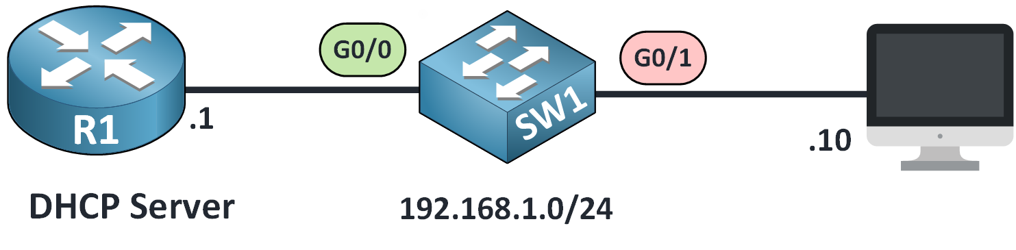
Figure 1 – DHCP Snooping Configuration Topology
Enable DHCP Snooping
First, we need to enable the feature globally:
SW1# conf t
Enter configuration commands, one per line. End with CNTL/Z.
SW1#(config)# ip dhcp snooping
Define VLAN to Protect
Next, we specify the VLAN where DHCP Snooping should operate.
By default, we'll use VLAN 1.
SW1#(config)# ip dhcp snooping vlan 1This tells the switch to inspect and filter DHCP traffic only on this VLAN.
Set Trusted Interface
By default, all interfaces are untrusted, which means the switch blocks DHCP replies (like Offer and ACK) from those ports.
You need to trust the interface that connects to the legitimate DHCP server:
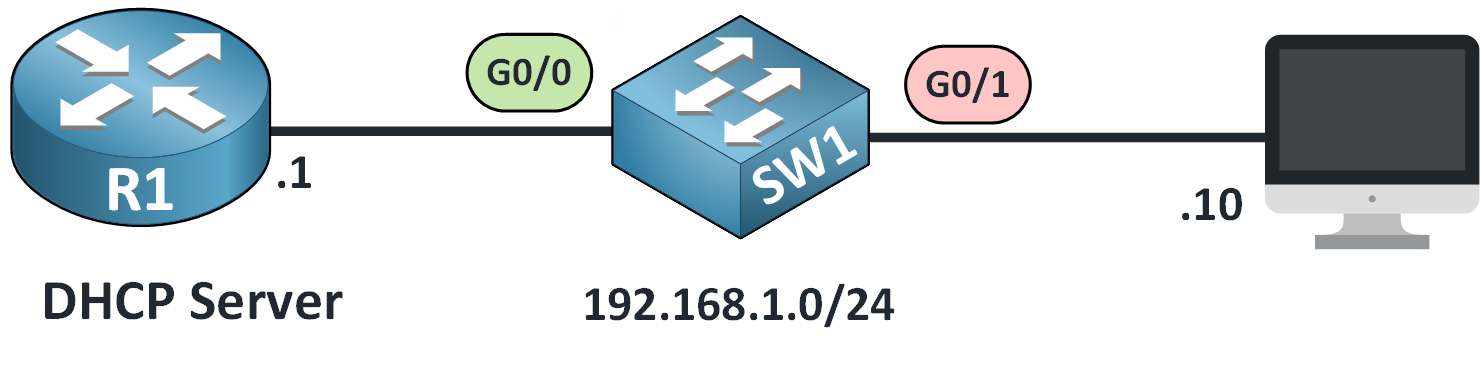
Figure 2 – Setting a Trusted Interface for DHCP Snooping
SW1(config)# int g0/0
SW1(config-if)# ip dhcp snooping trust
This allows DHCP messages from the server to reach clients. All other interfaces remain untrusted to block rogue DHCP servers.
Disabling Option 82
Cisco switches add
Option 82to DHCP messages by default.
In simple networks (without relay agents), this may cause the DHCP server to reject requests.Disable it to avoid problems:
SW1(config)# no ip dhcp snooping information option
SW1(config)# end
This topic will be explained in more detail later.
Verify the Configuration
To validate your DHCP Snooping configuration, run the following command:
SW1# show ip dhcp snooping
Switch DHCP snooping is enabled
Switch DHCP gleaning is disabled
DHCP snooping is configured on following VLANs:
1
DHCP snooping is operational on following VLANs:
1
DHCP snooping is configured on the following L3 Interfaces:

Insertion of option 82 is disabled
   circuit-id default format: vlan-mod-port
   remote-id: 50f6.1504.7a00 (MAC)
Option 82 on untrusted port is not allowed
Verification of hwaddr field is enabled
Verification of giaddr field is enabled
DHCP snooping trust/rate is configured on the following Interfaces:

Interface                  Trusted    Allow option    Rate limit (pps)
-----------------------    -------    ------------    ----------------
GigabitEthernet0/0         yes        yes             unlimited
  Custom circuit-ids:
This output confirms that your DHCP Snooping configuration is active, trusted ports are correctly defined, and Option 82 is disabled.
View the Binding Table
The switch dynamically tracks legitimate clients:
SW1# show ip dhcp snooping binding
MacAddress          IpAddress        Lease(sec)  Type           VLAN  Interface
------------------  ---------------  ----------  -------------  ----  ------------
00:50:79:66:68:7B   192.168.10.10    86390       dhcp-snooping   1    GigabitEthernet0/1
Total number of bindings: 1
What this tells us:
The MAC address and IP address of the client are recorded
The interface and VLAN match our setup
The lease time shows that the IP is still valid
This table allows the switch to track legitimate DHCP clients and block traffic from unauthorized sources.
Answer the question below
By default, what do Cisco switches add to DHCP messages that may need to be disabled in simple networks?
After completing your DHCP Snooping configuration, it's essential to protect the switch from excessive DHCP traffic that could lead to flood attacks.
A flood attack?
An attacker could flood the switch with fake DHCP Discover messages. This overloads the switch CPU and may cause:
The switch to stop processing DHCP properly
Security checks like DHCP Snooping to fail
Interfaces to become unstable
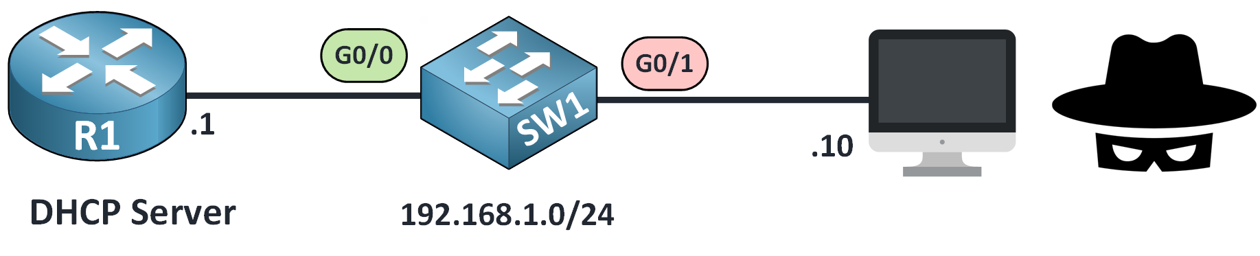
Figure 3 – DHCP Snooping Rate Limiting to Prevent Flood Attacks
To prevent this, we set a rate limit on how many DHCP packets are allowed per second.
Configure Rate Limiting
Here's how to apply a limit of 10 packets per second on a client-facing interface.
SW1# conf t
Enter configuration commands, one per line. End with CNTL/Z.
SW1(config)# interface g0/1
SW1(config-if)# ip dhcp snooping limit rate 10
If the interface receives more than 10 DHCP packets per second, it will automatically go into the err-disabled state.
Example: Interface Exceeds Limit
If an interface receives DHCP messages exceeding the configured limit, the switch generates logs saying the interface is now set to err-disabled (shutdown).
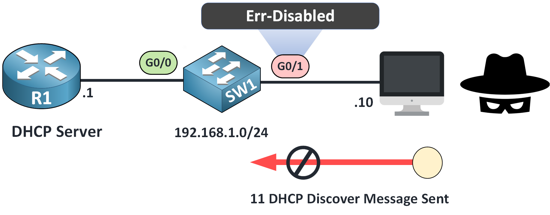
Figure 4 – DHCP Rate Limit Exceeded: Interface Set to Err-Disabled
When the limit is exceeded, the switch logs messages like:
SW1#
*Jan 22 22:08:52.275: %DHCP_SNOOPING-4-DHCP_SNOOPING_ERRDISABLE_WARNING: DHCP Snooping received 11 DHCP packets on interface Gi0/1

*Jan 22 22:08:52.275: %DHCP_SNOOPING-4-DHCP_SNOOPING_RATE_LIMIT_EXCEEDED: The interface Gi0/1 is receiving more than the threshold set

*Jan 22 22:08:52.275: %PM-4-ERR_DISABLE: dhcp-rate-limit error detected on Gi0/1, putting Gi0/1 in err-disable state

*Jan 22 22:08:53.278: %LINEPROTO-5-UPDOWN: Line protocol on Interface Gi0/1, changed state to down

*Jan 22 22:08:54.277: %LINK-3-UPDOWN: Interface GigabitEthernet0/1, changed state to down
The interface is now in the err-disabled state and cannot process traffic.
Answer the question below
What type of attack can overload the switch CPU by sending excessive DHCP Discover messages?
When an interface enters the err-disabled state due to DHCP rate limiting, it stops forwarding any traffic. This is a safety mechanism, but it can disrupt connectivity.
Manual Recovery
To manually bring the interface back up, use the following steps:
SW1# conf t
Enter configuration commands, one per line. End with CNTL/Z.
SW1(config)# interface g0/1
SW1(config-if)# shutdown
%LINK-5-CHANGED: Interface GigabitEthernet0/1, changed state to administratively down
%LINEPROTO-5-UPDOWN: Line protocol on Interface GigabitEthernet0/1, changed state to down

SW1(config-if)# no shutdown
%LINK-5-CHANGED: Interface GigabitEthernet0/1, changed state to up
%LINEPROTO-5-UPDOWN: Line protocol on Interface GigabitEthernet0/1, changed state to up

SW1(config-if)# end
This shuts the interface down and brings it back up, clearing the error state. It's effective, but imagine doing this on multiple interfaces during an attack. It's not scalable.
Automatic Recovery with Error Disabled Recovery
Cisco switches offer a feature called Error Disabled Recovery, which lets the switch automatically re-enable interfaces after a timeout.
Let's walk through how to configure it.Step 1 - Check Current Recovery Settings
Use this command to see if DHCP-related recovery is enabled:
SW1# show errdisable recovery
ErrDisable Reason            Timer Status
-----------------            --------------
arp-inspection               Disabled
bpduguard                    Disabled
channel-misconfig (STP)      Disabled
dhcp-rate-limit              Disabled
dtp-flap                     Disabled
gbic-invalid                 Disabled
inline-power                 Disabled
l2ptguard                    Disabled
link-flap                    Disabled
// OUTPUT OMITTED FOR CLARITY

Timer interval: 300 seconds

Interfaces that will be enabled at the next timeout:
Above you can see the list of causes (like
bpduguard,dhcp-rate-limit, etc.) with their recovery status and timer.Our cause, dhcp-rate-limit, is disabled.
Step 2 - Enable Recovery for DHCP Rate Limit
To activate it:
SW1# conf t
Enter configuration commands, one per line. End with CNTL/Z.
SW1(config)# errdisable recovery cause dhcp-rate-limit
You can also adjust how long the switch waits before reactivating the interface (default is 300 seconds):
SW1(config)# errdisable recovery interval 60
SW1(config)# end
This sets the timeout to 60 seconds.
Step 3 - Verify the New Settings
Once configured, confirm with:
SW1# show errdisable recovery
ErrDisable Reason            Timer Status
-----------------            --------------
arp-inspection               Disabled
bpduguard                    Disabled
channel-misconfig (STP)      Disabled
dhcp-rate-limit              Enabled
dtp-flap                     Disabled
gbic-invalid                 Disabled
inline-power                 Disabled
l2ptguard                    Disabled
link-flap                    Disabled
// OUTPUT OMITTED FOR CLARITY

Interface       Errdisable reason       Time left(sec)
---------       -----------------       --------------
unicast-flood                Disabled
vmps                         Disabled
psp                          Disabled
dual-active-recovery         Disabled
evc-lite input mapping fa    Disabled
Recovery command: "clear     Disabled

Timer interval: 60 seconds

Interfaces that will be enabled at the next timeout:

Interface       Errdisable reason       Time left(sec)
---------       -----------------       --------------
Gi0/1            dhcp-rate-limit          45
If an interface was shut down due to rate limiting, it will now appear in the list of interfaces scheduled for recovery:
This means interface GigabitEthernet0/1 will come back up in 45 seconds.
Recovery in Action
When the timer expires, the switch tries to re-enable the port. Here's what that looks like in the logs:
*Jan 22 22:16:52.290: %PM-4-ERR_RECOVER: Attempting to recover from dhcp-rate-limit err-disable state on Gi0/1

*Jan 22 22:16:54.323: %LINK-3-UPDOWN: Interface GigabitEthernet0/1, changed state to up

*Jan 22 22:16:55.324: %LINEPROTO-5-UPDOWN: Line protocol on Interface Gi0/1, changed state to up
At this point, the interface is fully functional again without requiring manual intervention.
Answer the question below
What feature allows a switch to automatically bring an interface out of the err-disabled state after a timeout?
When DHCP Snooping is enabled, a Cisco switch automatically inserts a special field into DHCP messages called
Option 82.This option includes details like the VLAN number and the switch port where the client is connected. In more advanced networks, a DHCP relay agent usually adds Option 82 to help the server track the origin of the request.
But in a simple network like ours, this behavior can cause problems.
What's the Issue?
The switch isn't acting as a real relay agent, but it still adds Option 82 to outgoing DHCP requests.
Here's what happens:
The client sends a DHCP DISCOVER.
The switch inserts Option 82 into the message.
The DHCP server sees it and rejects the request, thinking it's invalid.
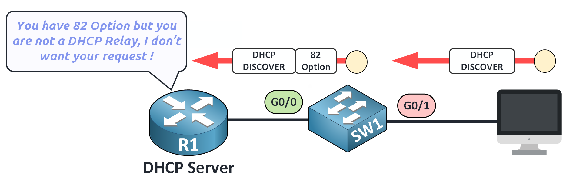
Figure 5 – DHCP Option 82 Issue with Non-Relay Switch
As shown above, the server says:
"You have Option 82, but you're not a DHCP Relay. I don't want your request!"This prevents the client from getting an IP address.
How to Fix It: Disable Option 82
To resolve this, we disable Option 82 on the switch:
SW1# conf t
Enter configuration commands, one per line.  End with CNTL/Z.
SW1(config)# no ip dhcp snooping information option
After running this command, the switch stops modifying the DHCP messages.
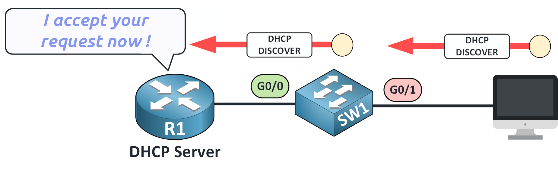
Figure 6 – Disabling Option 82 to Allow Valid DHCP Requests
The server sees the client's request as valid and responds normally.
Answer the question below
What should you disable if DHCP requests are rejected by the server?
Let's take a moment to review everything you've learned.
A strong DHCP Snooping configuration protects your network from rogue servers, prevents DHCP starvation attacks, and improves Layer 2 security.
By understanding how it works and how to configure it properly, you can prevent many potential issues in a switched network.
To properly secure your switch environment, make sure your DHCP Snooping configuration includes all of the following steps.
Feature
What It Does
Why It Matters
Enable DHCP Snooping
Activates the feature globally on the switch
Protects the network from unauthorized DHCP replies
Define VLANs
Applies DHCP Snooping only to specified VLANs
Limits the protection to relevant parts of the network
Set Trusted Interfaces
Marks interfaces connected to valid DHCP servers as trusted
Allows legitimate DHCP messages to pass
Disable Option 82
Prevents the switch from adding Option 82 to DHCP messages
Ensures compatibility with basic DHCP servers
Rate Limiting
Controls the number of DHCP packets per second per port
Prevents DoS attacks and switch CPU overload
Auto-Recovery (Errdisable)
Re-enables ports automatically after a rate-limit violation
Avoids manual intervention and maintains uptime
Binding Table
Tracks MAC, IP, VLAN, and interface of DHCP clients
Validates traffic and blocks spoofed packets
Table 1 – Summary of DHCP Snooping Configuration Features
By combining these elements, you strengthen the security of your Layer 2 infrastructure. DHCP Snooping filters untrusted sources and provides the foundation for features like Dynamic ARP Inspection and IP Source Guard.
If you want to explore advanced behaviors or hardware-specific details, you can refer to the official Cisco guide: Configuring DHCP Snooping
Answer the question below
Click 'Complete' to continue