A collision domain is a section of a network where devices share the same transmission medium.
If two devices try to send data at the same time, their signals interfere, causing a collision.
As the name suggests, it is a zone where collisions can happen.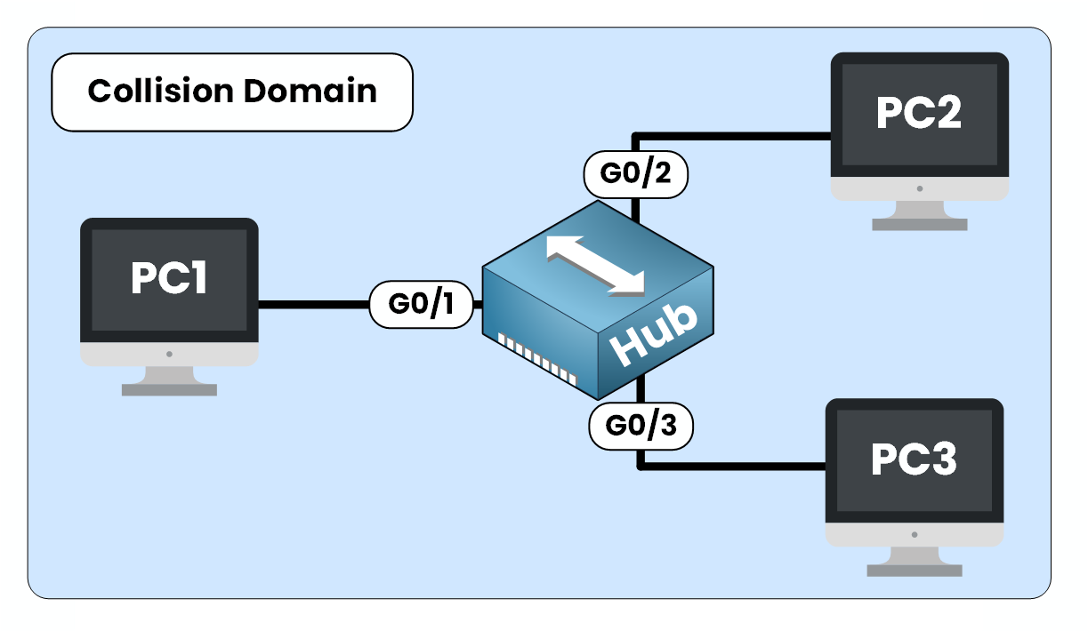
Figure 1 – All devices connected to the hub share the same collision domain
When this happens, the data gets corrupted and must be resent. This causes delays and negatively impacts network performance. The more devices that share the same collision domain, the higher the risk of collisions.
Let’s now see how this works in practice.
Answer the question below
What happens if two devices send data at the same time?
A hub operates at Layer 1 (Physical Layer) of the OSI model.
It is a dumb device that forwards data to every port, regardless of the destination. It doesn’t inspect traffic or make any forwarding decisions.In other words, all ports on a hub belong to a single collision domain.
Case 1 — No Collision
In a hub-based network, imagine PC1 sends data to PC2.
From PC1:
C:\> ping 192.168.1.2
Pinging 192.168.1.2 with 32 bytes of data:
Reply from 192.168.1.2: bytes=32 time<1ms TTL=128
Reply from 192.168.1.2: bytes=32 time<1ms TTL=128
Reply from 192.168.1.2: bytes=32 time<1ms TTL=128
Reply from 192.168.1.2: bytes=32 time<1ms TTL=128

Ping statistics for 192.168.1.2:
    Packets: Sent = 4, Received = 4, Lost = 0 (0% loss)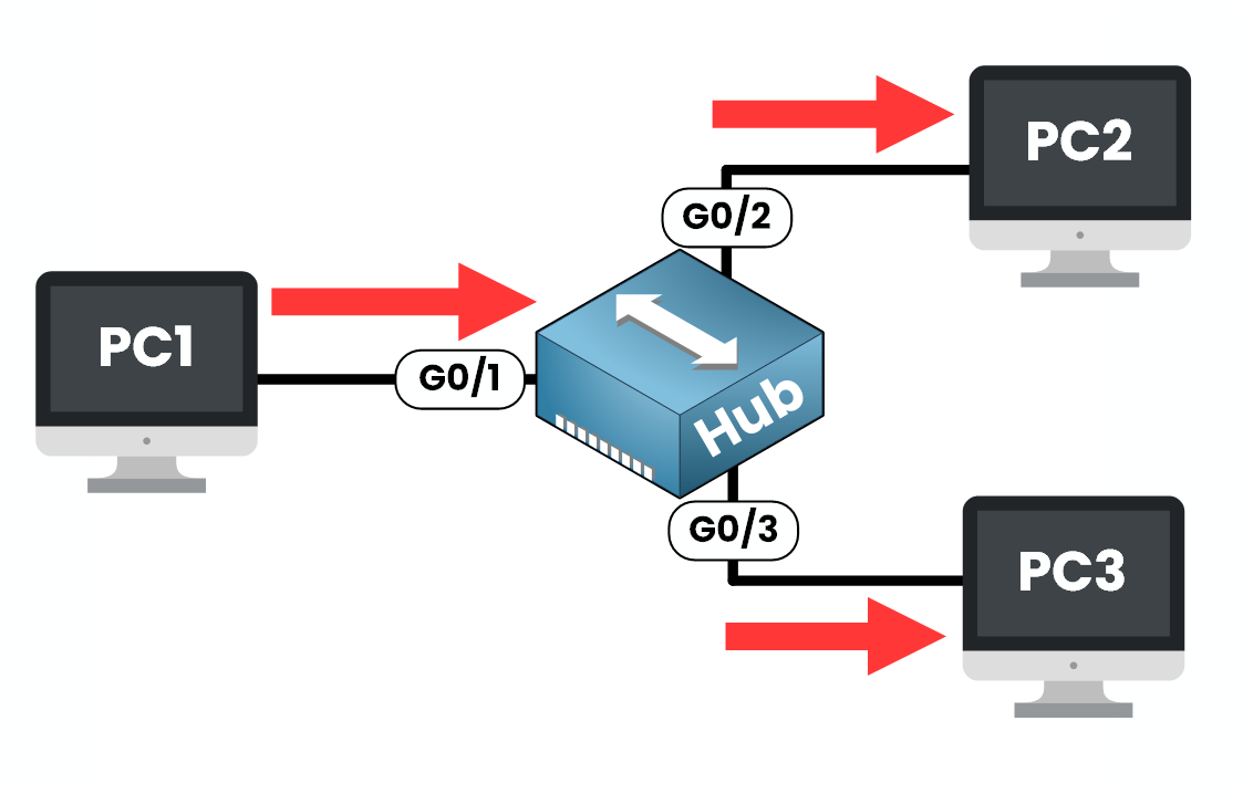
Figure 2 – hub broadcasts it to all ports without causing a collision
Since the hub broadcasts the signal to all ports, PC3 also receives the frame, but it simply ignores it.
As only one device is transmitting, there’s no collision.Case 2 — Collision Occurs
Now, suppose PC2 and PC3 both try to send data to PC1 at the same time.
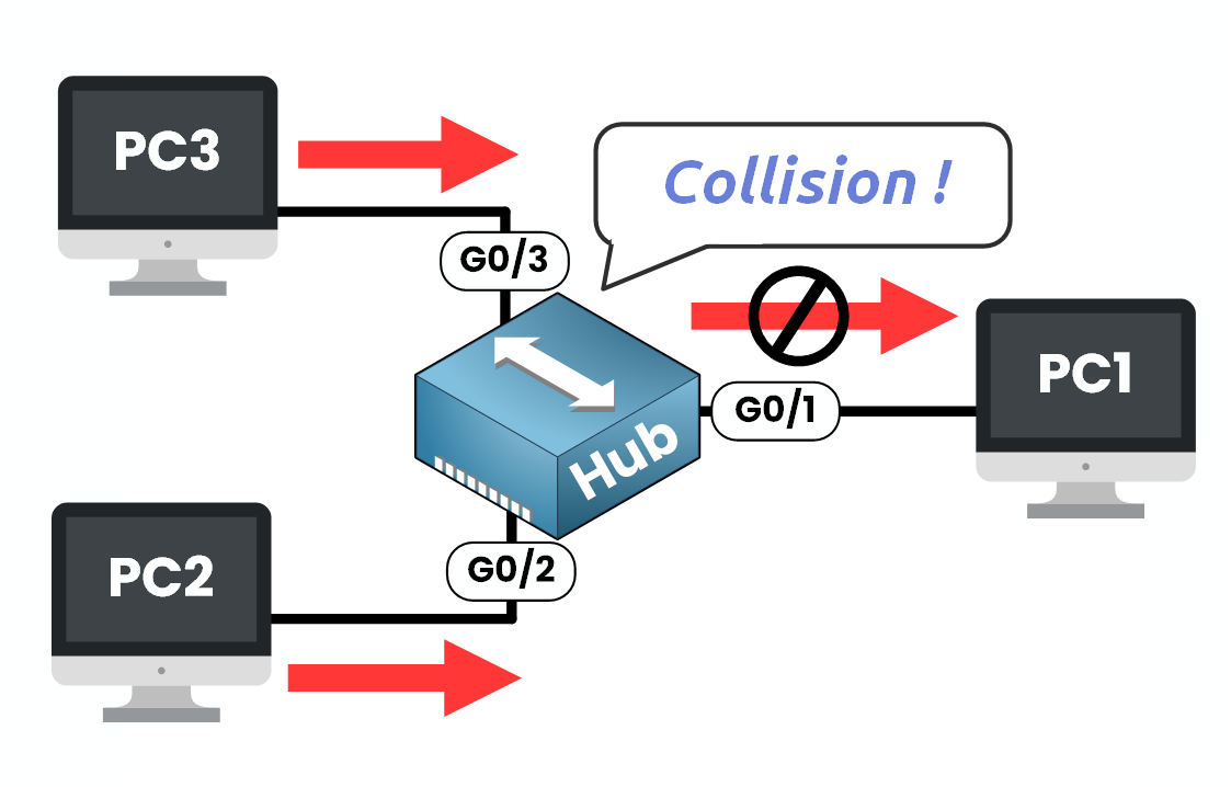
Figure 3 – PC2 and PC3 send data simultaneously, causing a collision
Since all ports on a hub share the same collision domain, their signals collide on the link going to PC1 (Gi0/1).
This collision corrupts the data, forcing both PCs to wait and retransmit, which introduces delays.
As networks grew, hubs became a major performance bottleneck due to frequent collisions. To address this, bridges were introduced.
Answer the question below
At which OSI layer does a hub operate?
To reduce collisions, bridges were introduced as an improvement over hubs.
A bridge operates at Layer 2 (Data Link Layer) of the OSI model.
It connects two segments of a network and acts as a filter. It examines the MAC address of incoming frames and only forwards traffic between segments when necessary.This process splits the network into two separate collision domains.
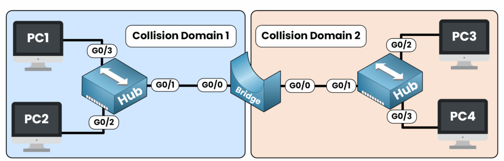
Figure 4 – A bridge splits the network into two collision domains to reduce collisions
If a collision occurs in one segment, it remains isolated and does not impact the other.
This reduces the scope of collisions in hub-based networks.However, inside each segment collisions can still occur between devices.
While bridges helped reduce the scope of collisions, the real breakthrough came with switches.Answer the question below
True or False: A bridge increases the number of collisions in a network.
A switch is a modern network device that operates at Layer 2 (Data Link Layer) of the OSI model. You can think of it as a multiport bridge.
Unlike a hub, a switch does not forward data to all ports.
Instead, it learns MAC addresses and forwards each frame only to the correct destination port.Each Port Creates Its Own Collision Domain
Each port on a switch forms its own collision domain.
This means that traffic received on one port does not interfere with traffic on another port.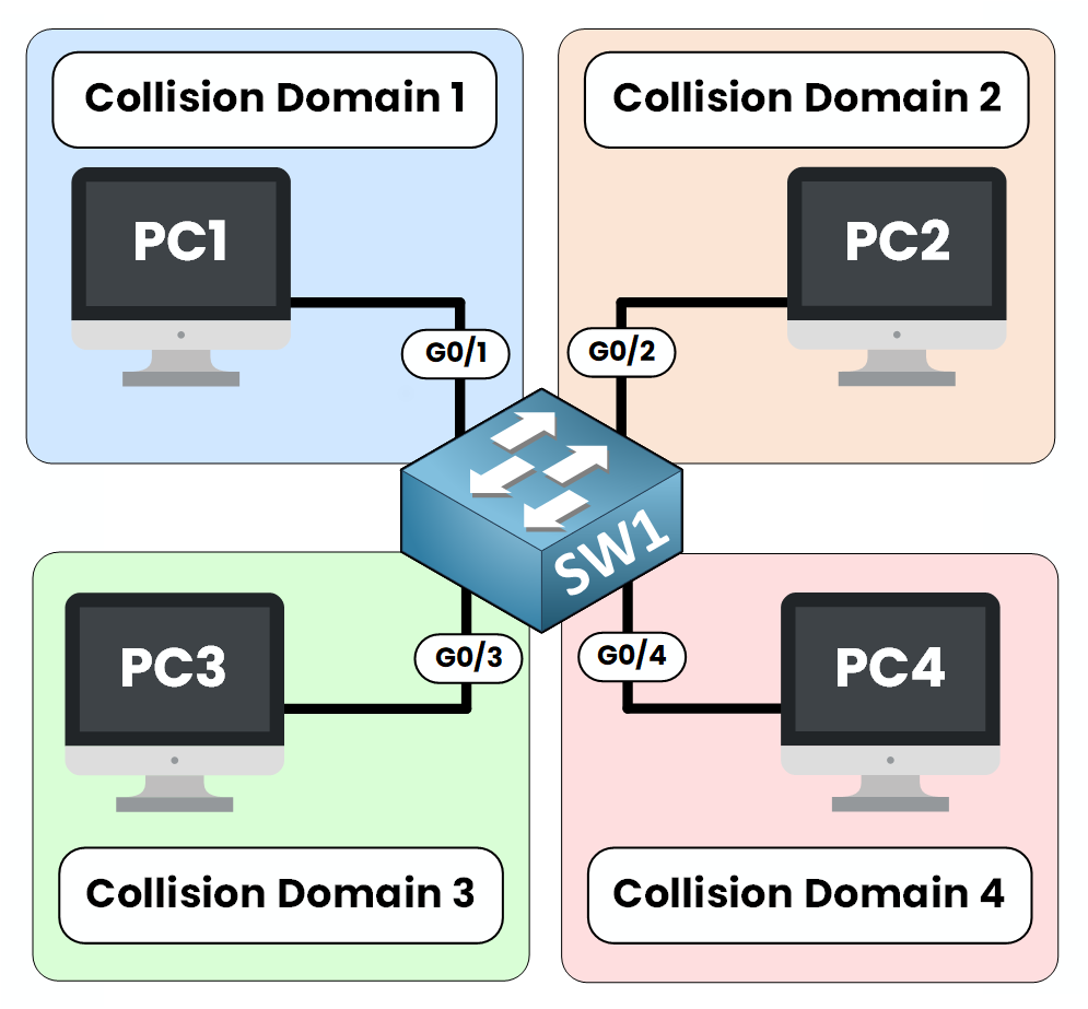
Figure 5 – Each switch port creates a separate collision domain, isolating traffic between devices
PC1 is connected to Gi0/1
PC2 is connected to Gi0/2
PC3 is connected to Gi0/3
PC4 is connected to Gi0/4
Each of these ports operates independently.
We can verify this directly on the switch by checking the interface statistics.SW1# show interfaces g0/1 GigabitEthernet0/1 is up, line protocol is up Full-duplex, 1000Mb/s 0 collisionsIf we check another port:
SW1# show interfaces g0/2
GigabitEthernet0/2 is up, line protocol is up
  Full-duplex, 1000Mb/s
  0 collisions
Each interface has its own counters and operates in full-duplex mode.
Full-duplex communication allows a device to send and receive at the same time.
Because of this, collisions no longer occur on switch ports.Example — Two Devices Send Data at the Same Time
In Figure 6, PC2 and PC3 both send data to PC1 at the same time:
PC2 sends traffic through Gi0/2
PC3 sends traffic through Gi0/3
PC1 is connected to Gi0/1
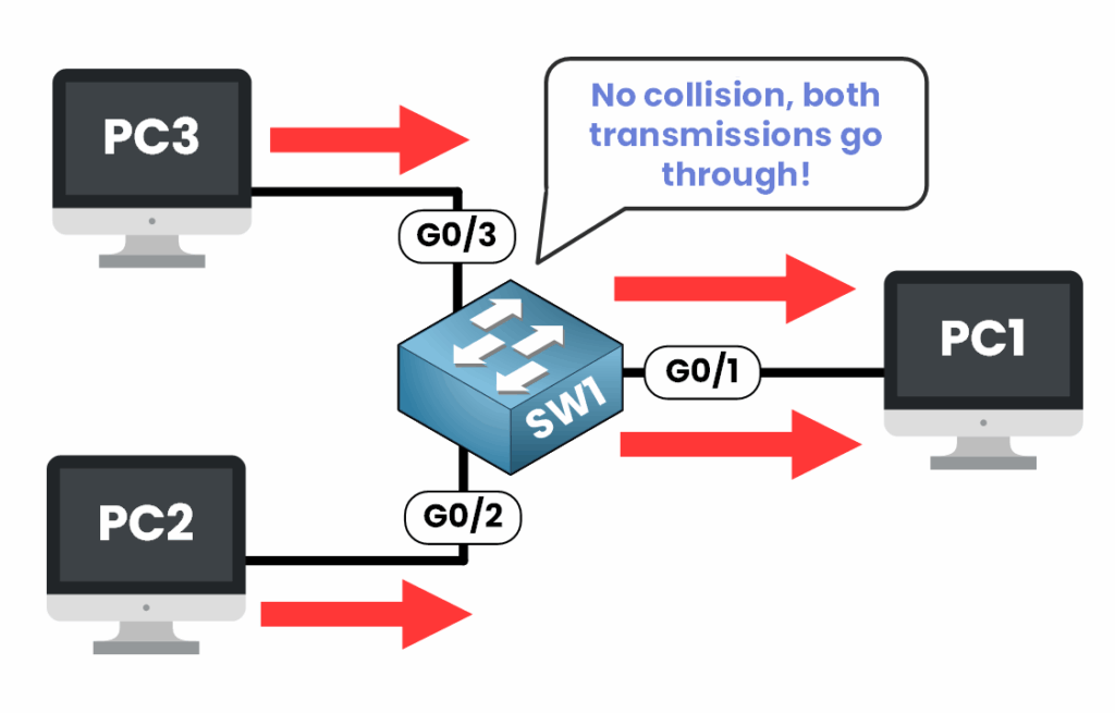
Figure 6 – Switch forwards frames from PC2 and PC3 to PC1 without collision, handling each transmission separately
The switch receives frames on Gi0/2 and Gi0/3 independently and forwards them to Gi0/1 without mixing the signals.
Answer the question below
Each switch port creates its own ________ ______.
Collision domains are directly influenced by the type of device used in the network:
A Hub (Layer 1): forwards all traffic to every port, one large collision domain
A Bridge (Layer 2): separates segments, one collision domain per segment
A Switch (Layer 2): assigns a separate collision domain to each port, eliminates collisions completely
Today, switches are the standard in Ethernet networks.
But for troubleshooting older environments or preparing for certifications like the CCNA, it’s important to understand how each device affects the collision domain.Answer the question below
Which device eliminates collisions completely?