Now that you understand why GRE is used, we can build the tunnel.
In this lab, R1 and R2 are connected through two ISP routers across the Internet.
The Internet acts as the underlay network, while the GRE tunnel will create the overlay connection between the two sites.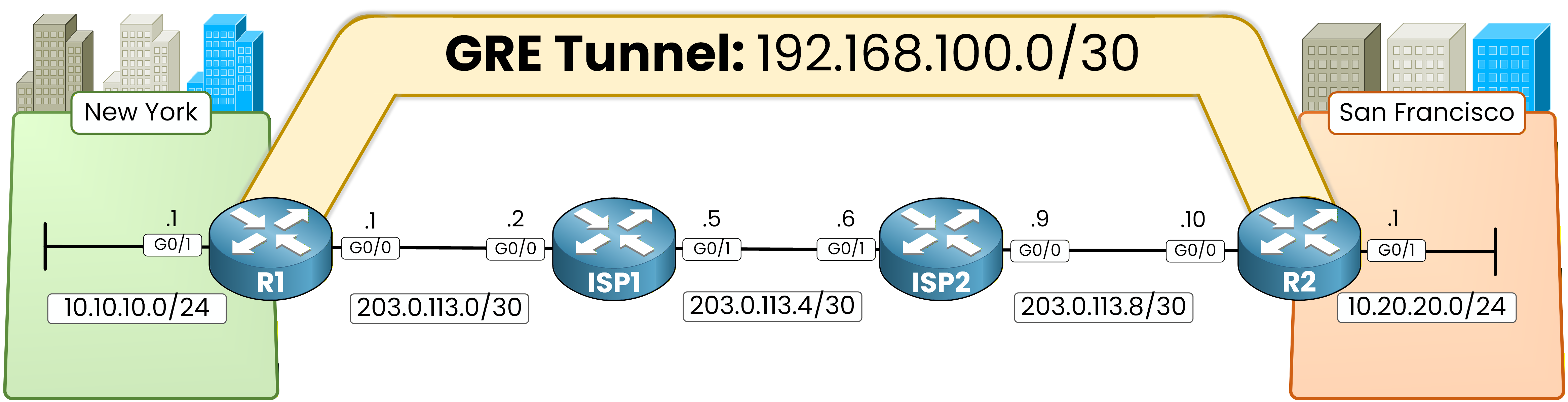
Figure 1 - GRE lab topology
Before creating the GRE tunnel, the underlay network must be working correctly.
This means the ISP routers must be able to route traffic between the tunnel endpoints.First, configure static routes on the ISP routers so they can forward traffic between the tunnel endpoints.
This ensures the underlay network can reach the GRE tunnel endpoints.ISP1 Static Routing

Figure 2 - ISP1 static routing
ISP1 must know how to reach the remote WAN link behind ISP2.
On ISP1, configure the following static route:ISP1# conf t Enter configuration commands, one per line. End with CNTL/Z. ISP1(config)# ip route 203.0.113.8 255.255.255.252 203.0.113.6This route allows ISP1 to forward traffic toward the remote WAN subnet behind ISP2.
ISP2 Static Routing
ISP2 must also know how to reach the remote WAN link behind ISP1.

Figure 3 - ISP2 static routing
Configure the following route on ISP2:
ISP2# conf t
Enter configuration commands, one per line.  End with CNTL/Z.
ISP2(config)# ip route 203.0.113.0 255.255.255.252 203.0.113.5
At this stage, the underlay network can route traffic between R1 and R2.
Configure Default Route
Each enterprise router must also have a default route pointing toward the ISP.

Figure 4 - Default route configuration
On R1:
R1(config)# ip route 0.0.0.0 0.0.0.0 203.0.113.2On R2:
R2(config)# ip route 0.0.0.0 0.0.0.0 203.0.113.9These routes ensure that Internet-bound traffic is forwarded to the ISP routers.
Answer the question below
What is the next hop of the default route configured on R1?
GRE Tunnel Configuration
Now we can create the GRE tunnel between R1 and R2.
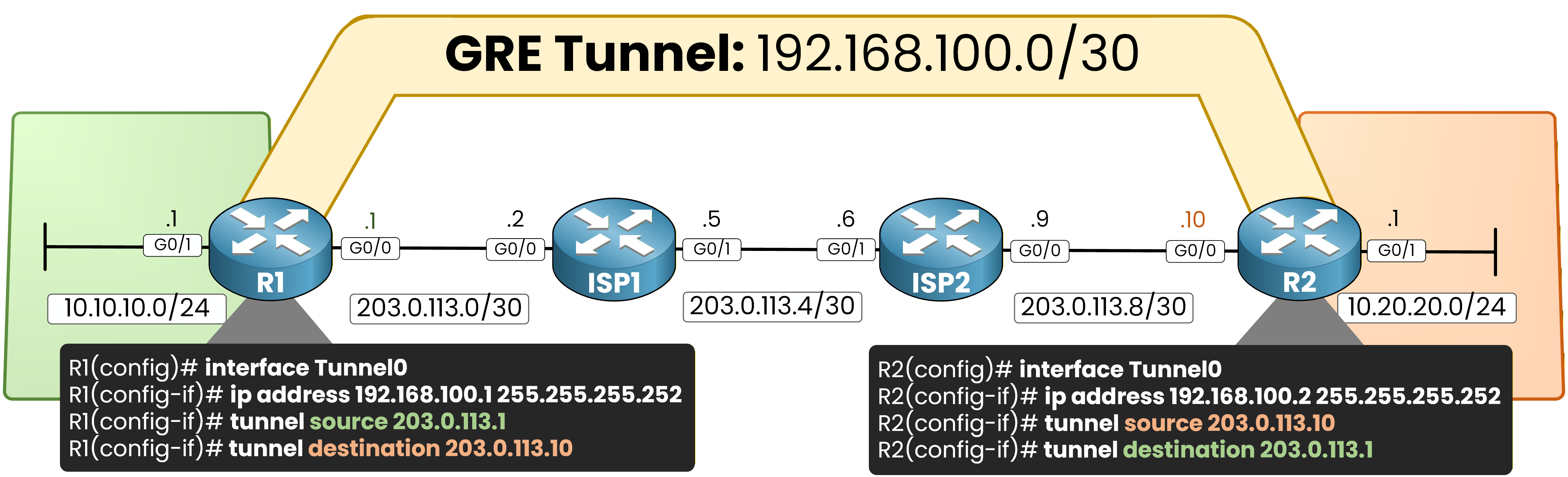
Figure 5 - GRE tunnel configuration
On R1:
R1(config)# int tunnel0
%LINEPROTO-5-UPDOWN: Line protocol on Interface Tunnel0, changed state to down
R1(config-if)# ip address 192.168.100.1 255.255.255.252
R1(config-if)# tunnel source 203.0.113.1
R1(config-if)# tunnel destination 203.0.113.10
%LINEPROTO-5-UPDOWN: Line protocol on Interface Tunnel0, changed state to up
R1(config-if)# end
On R2:
R2(config)# int tunnel0
%LINEPROTO-5-UPDOWN: Line protocol on Interface Tunnel0, changed state to down
R2(config-if)# ip address 192.168.100.2 255.255.255.252
R2(config-if)# tunnel source 203.0.113.10
R2(config-if)# tunnel destination 203.0.113.1
%LINEPROTO-5-UPDOWN: Line protocol on Interface Tunnel0, changed state to up
%OSPF-5-ADJCHG: Process 1, Nbr 1.1.1.1 on Tunnel0 from LOADING to FULL, Loading Done
R2(config-if)# end
This configuration creates a GRE tunnel between R1 and R2 using the Internet as the transport network.
Once the tunnel is established, OSPF forms an adjacency and exchanges routes between the sites.OSPF over GRE
Once the tunnel is created, we will run OSPF across the GRE tunnel so the routers can exchange routes dynamically.
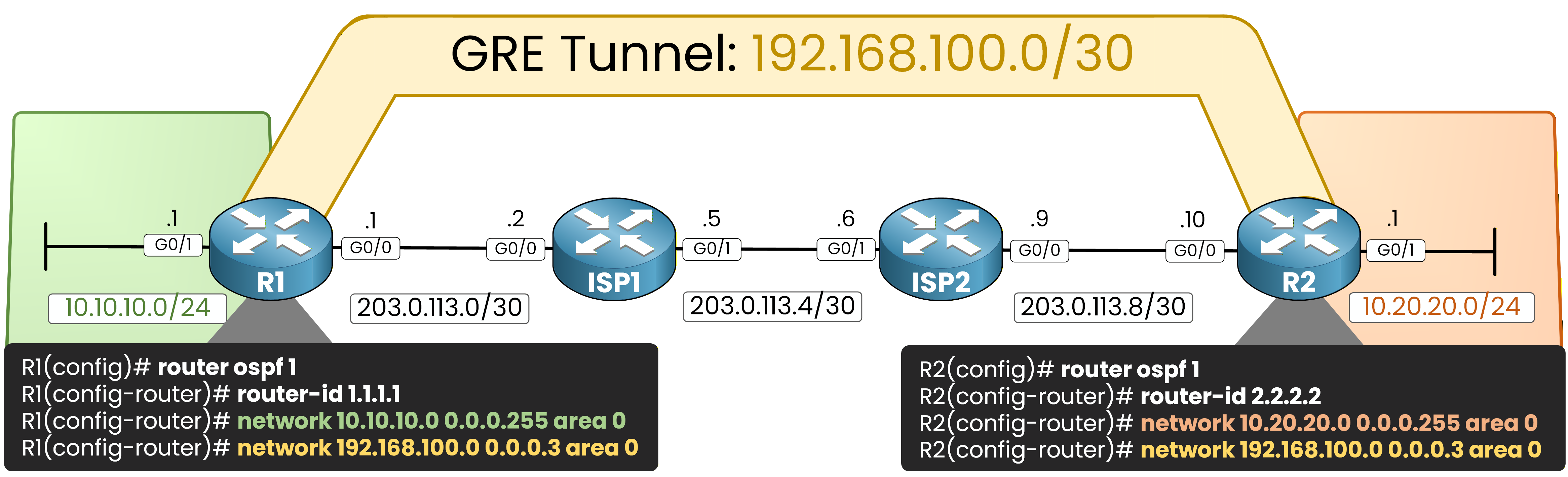
Figure 6 - OSPF over GRE
On R1:
40 % Complete: you’re making great progress
Ready to pass your CCNP exam?