VRF (Virtual Routing and Forwarding) allows a router to maintain multiple independent routing tables on the same physical device.
Each VRF acts as a separate virtual router with its own interfaces and routes.The concept is the same as VLANs, but at a different layer.
VLANs isolate traffic at Layer 2 by creating separate MAC address tables.
VRFs isolate traffic at Layer 3 by creating separate routing tables.
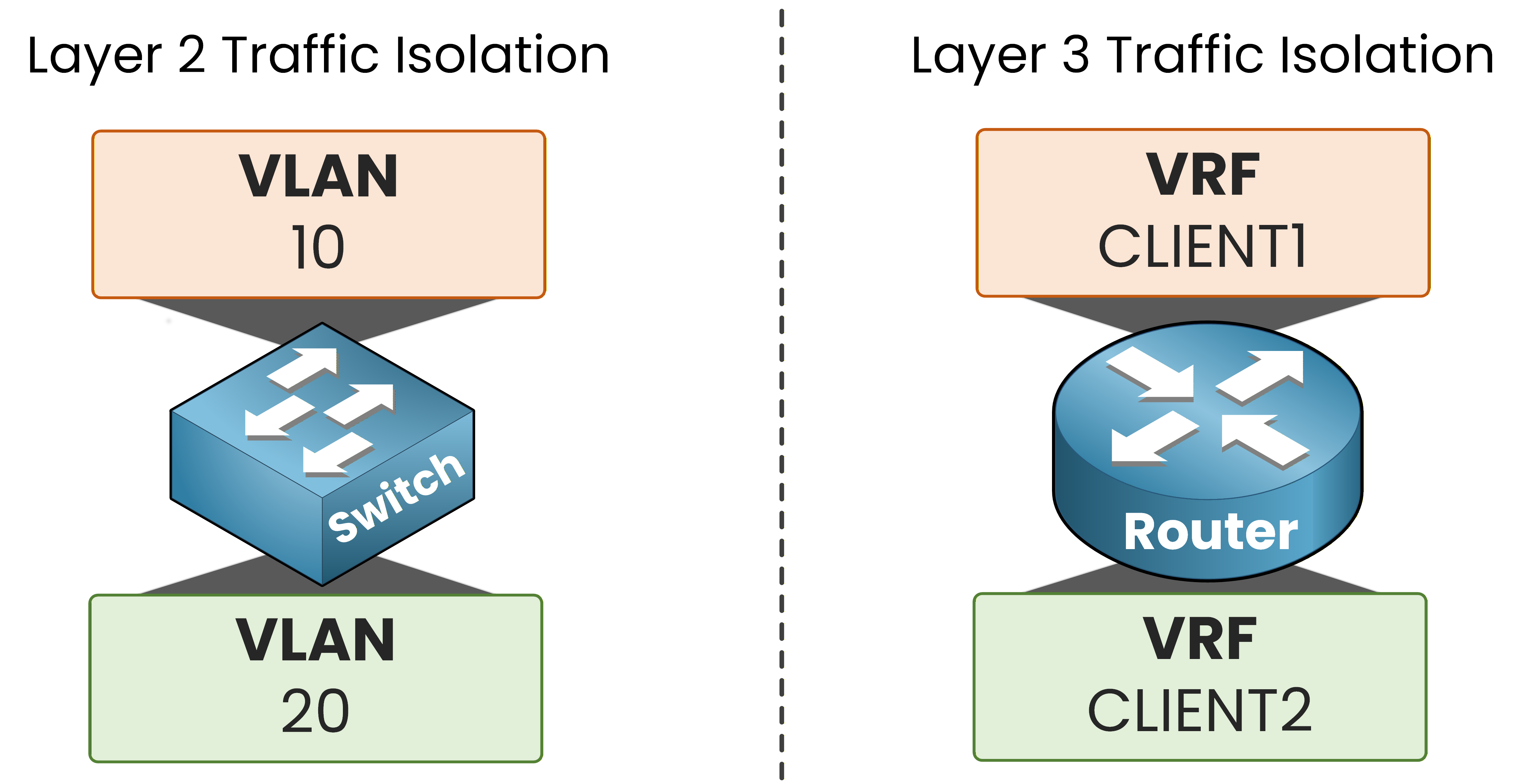
Figure 1 – VLANs vs VRFs
But in real service provider networks, your VRFs must travel across multiple routers end-to-end.
This is where VRF-Lite at the CCNP level begins.The Scenario
You are the network engineer of a service provider.
Two customers need connectivity through your ISP router.CLIENT1 has two sites: HQ1 and BR1.
CLIENT2 has two sites: HQ2 and BR2.
All four customer routers connect to your central ISP router through dedicated physical interfaces.
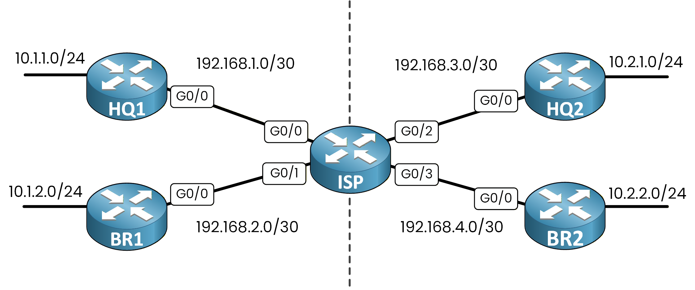
Figure 2 – ISP multi-customer topology
Your objective is clear: CLIENT1 and CLIENT2 must be completely isolated from each other, even though they share the same physical ISP router.
The VRF Solution
With VRF, you segment the network into isolated customer domains.
Each customer's links belong to its own VRF.CLIENT1 links (HQ1 and BR1) are shown in orange on the left.
CLIENT2 links (HQ2 and BR2) are shown in green on the right.
The dashed line represents the complete isolation between the two VRFs.
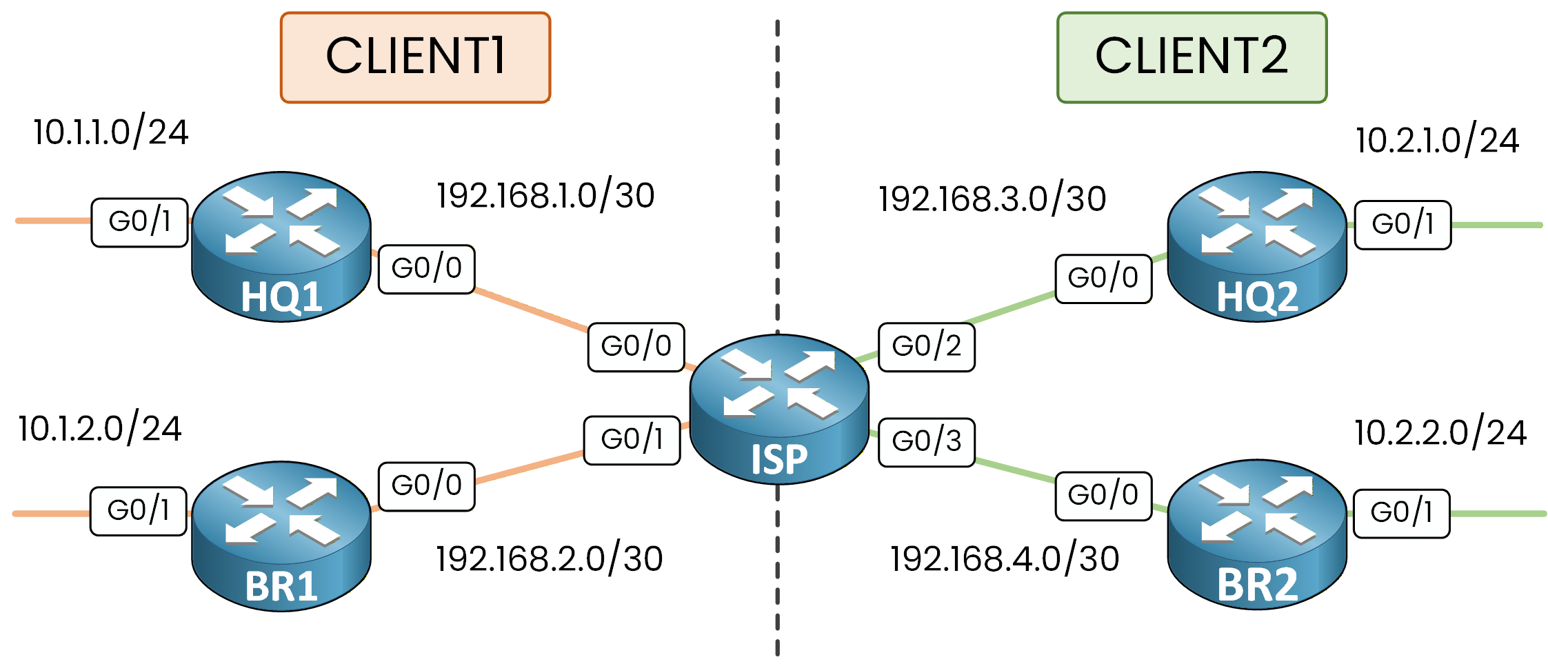
Figure 3 – VRF network segmentation
From the perspective of VRF CLIENT1, VRF CLIENT2 does not exist.
They share the same physical ISP router, but they live in completely separate worlds.Answer the question below
What does each VRF maintain to keep customer traffic separated?
The Modern Syntax: vrf definition
Older Cisco IOS used the
ip vrfcommand to create VRFs.
That is the legacy syntax, limited to IPv4 only.Modern Cisco IOS and IOS-XE use
vrf definition.
This command supports both IPv4 and IPv6 through address families.
This is the syntax you need for the CCNP ENCOR blueprint.Create the customer VRFs on every router in the topology.
On the ISP, create both VRFs:
ISP# conf t
Enter configuration commands, one per line.  End with CNTL/Z.
ISP(config)# vrf definition CLIENT1
ISP(config-vrf)# address-family ipv4
ISP(config-vrf-af)# exit-address-family
ISP(config-vrf)# exit

ISP(config)# vrf definition CLIENT2
ISP(config-vrf)# address-family ipv4
ISP(config-vrf-af)# exit-address-family
ISP(config-vrf)# exit
On HQ1, create VRF CLIENT1:
HQ1# conf t
Enter configuration commands, one per line.  End with CNTL/Z.
HQ1(config)# vrf definition CLIENT1
HQ1(config-vrf)# address-family ipv4
HQ1(config-vrf-af)# exit-address-family
HQ1(config-vrf)# exit
On BR1:
BR1# conf t
Enter configuration commands, one per line.  End with CNTL/Z.
BR1(config)# vrf definition CLIENT1
BR1(config-vrf)# address-family ipv4
BR1(config-vrf-af)# exit-address-family
BR1(config-vrf)# exit
On HQ2, create VRF CLIENT2:
HQ2# conf t
Enter configuration commands, one per line.  End with CNTL/Z.
HQ2(config)# vrf definition CLIENT2
HQ2(config-vrf)# address-family ipv4
HQ2(config-vrf-af)# exit-address-family
HQ2(config-vrf)# exit
On BR2:
BR2# conf t
Enter configuration commands, one per line.  End with CNTL/Z.
BR2(config)# vrf definition CLIENT2
BR2(config-vrf)# address-family ipv4
BR2(config-vrf-af)# exit-address-family
BR2(config-vrf)# exit
The
address-family ipv4block activates IPv4 routing inside this VRF.
Without it, the VRF exists but cannot process any IPv4 traffic.Answer the question below
Which command replaces ip vrf in modern IOS-XE for creating VRFs?
Your VRFs are defined on every router. Now you need to assign interfaces so that each customer's traffic stays inside its own VRF.
VRF Is Locally Significant
You assign interfaces to a VRF using the
vrf forwardingcommand.
A VRF is locally significant.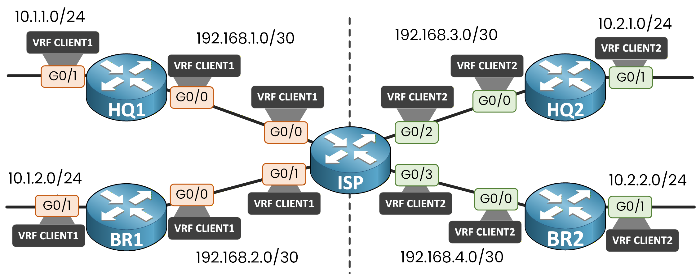
Figure 4 – VRF assignments on every interface
The other side of a link does not need the same VRF, or any VRF at all. In a typical ISP design, only the ISP interface facing the customer is in the customer VRF, and the CE router stays in its global table. In this lab, VRFs are configured on both the ISP router and the customer routers.
ISP Interface Configuration
Remember: applying
vrf forwardingto an interface removes any existing IP address.
Always assign the VRF first, then configure the IP.ISP(config)# interface G0/0 ISP(config-if)# vrf forwarding CLIENT1 ISP(config-if)# ip address 192.168.1.1 255.255.255.252 ISP(config-if)# no shutdown ISP(config-if)# exit ISP(config)# interface G0/1 ISP(config-if)# vrf forwarding CLIENT1 ISP(config-if)# ip address 192.168.2.1 255.255.255.252 ISP(config-if)# no shutdown ISP(config-if)# exit ISP(config)# interface G0/2 ISP(config-if)# vrf forwarding CLIENT2 ISP(config-if)# ip address 192.168.3.1 255.255.255.252 ISP(config-if)# no shutdown ISP(config-if)# exit ISP(config)# interface G0/3 ISP(config-if)# vrf forwarding CLIENT2 ISP(config-if)# ip address 192.168.4.1 255.255.255.252 ISP(config-if)# no shutdown ISP(config-if)# endCLIENT1 Router Interfaces
Each customer router needs the VRF on both its WAN interface (G0/0 toward ISP) and its LAN interface (G0/1).
On HQ1:
HQ1(config)# interface G0/0
HQ1(config-if)# vrf forwarding CLIENT1
HQ1(config-if)# ip address 192.168.1.2 255.255.255.252
HQ1(config-if)# no shutdown
HQ1(config-if)# exit

HQ1(config)# interface G0/1
HQ1(config-if)# vrf forwarding CLIENT1
HQ1(config-if)# ip address 10.1.1.1 255.255.255.0
HQ1(config-if)# no shutdown
HQ1(config-if)# end
On BR1:
BR1(config)# interface G0/0
BR1(config-if)# vrf forwarding CLIENT1
BR1(config-if)# ip address 192.168.2.2 255.255.255.252
BR1(config-if)# no shutdown
BR1(config-if)# exit

BR1(config)# interface G0/1
BR1(config-if)# vrf forwarding CLIENT1
BR1(config-if)# ip address 10.1.2.1 255.255.255.0
BR1(config-if)# no shutdown
BR1(config-if)# end
CLIENT2 Router Interfaces
On HQ2:
HQ2(config)# interface G0/0
HQ2(config-if)# vrf forwarding CLIENT2
HQ2(config-if)# ip address 192.168.3.2 255.255.255.252
HQ2(config-if)# no shutdown
HQ2(config-if)# exit

HQ2(config)# interface G0/1
HQ2(config-if)# vrf forwarding CLIENT2
HQ2(config-if)# ip address 10.2.1.1 255.255.255.0
HQ2(config-if)# no shutdown
HQ2(config-if)# end
On BR2:
BR2(config)# interface G0/0
BR2(config-if)# vrf forwarding CLIENT2
BR2(config-if)# ip address 192.168.4.2 255.255.255.252
BR2(config-if)# no shutdown
BR2(config-if)# exit

BR2(config)# interface G0/1
BR2(config-if)# vrf forwarding CLIENT2
BR2(config-if)# ip address 10.2.2.1 255.255.255.0
BR2(config-if)# no shutdown
BR2(config-if)# end
Answer the question below
Which command assigns an interface to a VRF?
Before configuring routing, verify that VRFs are correctly assigned on every router.
On the ISP:
ISP# show vrf
  Name                             Default RD            Protocols   Interfaces
  CLIENT1                          <not set>             ipv4        Gi0/0
                                                                     Gi0/1
  CLIENT2                          <not set>             ipv4        Gi0/2
                                                                     Gi0/3
On HQ1:
HQ1# show vrf
  Name                             Default RD            Protocols   Interfaces
  CLIENT1                          <not set>             ipv4        Gi0/0
                                                                     Gi0/1
On BR1:
BR1# show vrf
  Name                             Default RD            Protocols   Interfaces
  CLIENT1                          <not set>             ipv4        Gi0/0
                                                                     Gi0/1
On HQ2:
HQ2# show vrf
  Name                             Default RD            Protocols   Interfaces
  CLIENT2                          <not set>             ipv4        Gi0/0
                                                                     Gi0/1
On BR2:
BR2# show vrf
  Name                             Default RD            Protocols   Interfaces
  CLIENT2                          <not set>             ipv4        Gi0/0
                                                                     Gi0/1
Answer the question below
Which command shows the VRF-to-interface mapping on a router?
Your VRFs are deployed and your interfaces are assigned on every router.
But if you try to ping from HQ1's LAN to BR1's LAN right now, it fails.
Your ISP router has no routes to the remote LANs inside its VRF tables.
Each VRF is an independent routing domain. You need to add routes inside each one.IP Addressing Reference
Use this topology as a reference for the static routes you are about to configure.
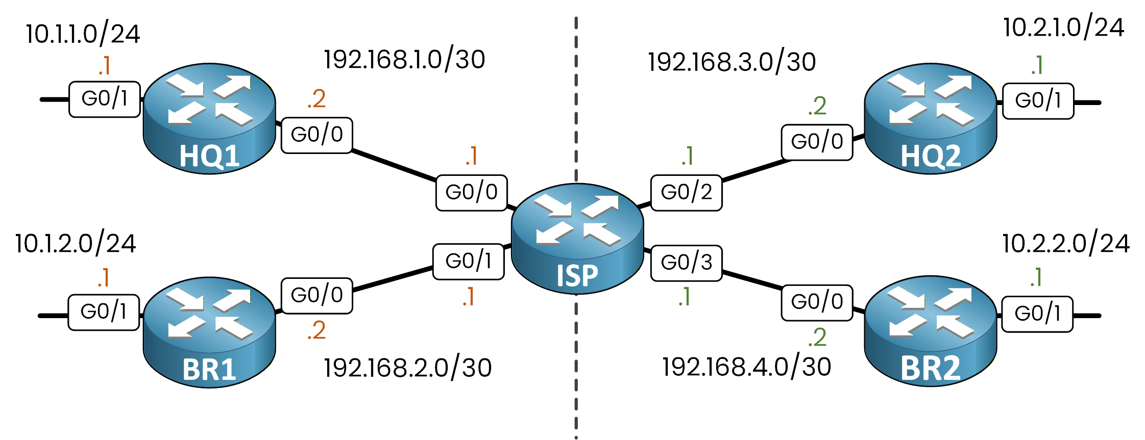
Figure 5 – IP addressing
Static Routes on the ISP Router
To add a static route inside a VRF, you use the
ip route vrfcommand.
A regularip routegoes into the global table. You need the VRF name to target the right table.ISP# conf t Enter configuration commands, one per line. End with CNTL/Z. ISP(config)# ip route vrf CLIENT1 10.1.1.0 255.255.255.0 192.168.1.2 ISP(config)# ip route vrf CLIENT1 10.1.2.0 255.255.255.0 192.168.2.2 ISP(config)# ip route vrf CLIENT2 10.2.1.0 255.255.255.0 192.168.3.2 ISP(config)# ip route vrf CLIENT2 10.2.2.0 255.255.255.0 192.168.4.2 ISP(config)# endDefault Routes on the Customer Routers
Each customer router needs a default route pointing back to the ISP inside its VRF.
HQ1# conf t Enter configuration commands, one per line. End with CNTL/Z. HQ1(config)# ip route vrf CLIENT1 0.0.0.0 0.0.0.0 192.168.1.1 HQ1(config)# endBR1# conf t Enter configuration commands, one per line. End with CNTL/Z. BR1(config)# ip route vrf CLIENT1 0.0.0.0 0.0.0.0 192.168.2.1 BR1(config)# endHQ2# conf t Enter configuration commands, one per line. End with CNTL/Z. HQ2(config)# ip route vrf CLIENT2 0.0.0.0 0.0.0.0 192.168.3.1 HQ2(config)# endBR2# conf t Enter configuration commands, one per line. End with CNTL/Z. BR2(config)# ip route vrf CLIENT2 0.0.0.0 0.0.0.0 192.168.4.1 BR2(config)# endAnswer the question below
Which command adds a static route inside a specific VRF?
Verifying VRF Routing Tables
Check that the routes appear in VRF CLIENT1 on the ISP:
ISP# show ip route vrf CLIENT1

Routing Table: CLIENT1
Codes: L - local, C - connected, S - static, R - RIP, M - mobile, B - BGP
       D - EIGRP, EX - EIGRP external, O - OSPF, IA - OSPF inter area
       N1 - OSPF NSSA external type 1, N2 - OSPF NSSA external type 2
       E1 - OSPF external type 1, E2 - OSPF external type 2
       i - IS-IS, su - IS-IS summary, L1 - IS-IS level-1, L2 - IS-IS level-2
       ia - IS-IS inter area, * - candidate default, U - per-user static route
       o - ODR, P - periodic downloaded static route, H - NHRP, l - LISP
       a - application route
       + - replicated route, % - next hop override, p - overrides from PfR

Gateway of last resort is not set

      10.0.0.0/24 is subnetted, 2 subnets
S        10.1.1.0 [1/0] via 192.168.1.2
S        10.1.2.0 [1/0] via 192.168.2.2
      192.168.1.0/24 is variably subnetted, 2 subnets, 2 masks
C        192.168.1.0/30 is directly connected, GigabitEthernet0/0
L        192.168.1.1/32 is directly connected, GigabitEthernet0/0
      192.168.2.0/24 is variably subnetted, 2 subnets, 2 masks
C        192.168.2.0/30 is directly connected, GigabitEthernet0/1
L        192.168.2.1/32 is directly connected, GigabitEthernet0/1
Testing Intra-VRF Connectivity
A regular
pinguses the global table.
To test connectivity inside a VRF, always useping vrf NAME.From BR1, ping HQ1's LAN using the source address of BR1's LAN interface.
Both sites are in VRF CLIENT1. The connectivity test succeeds.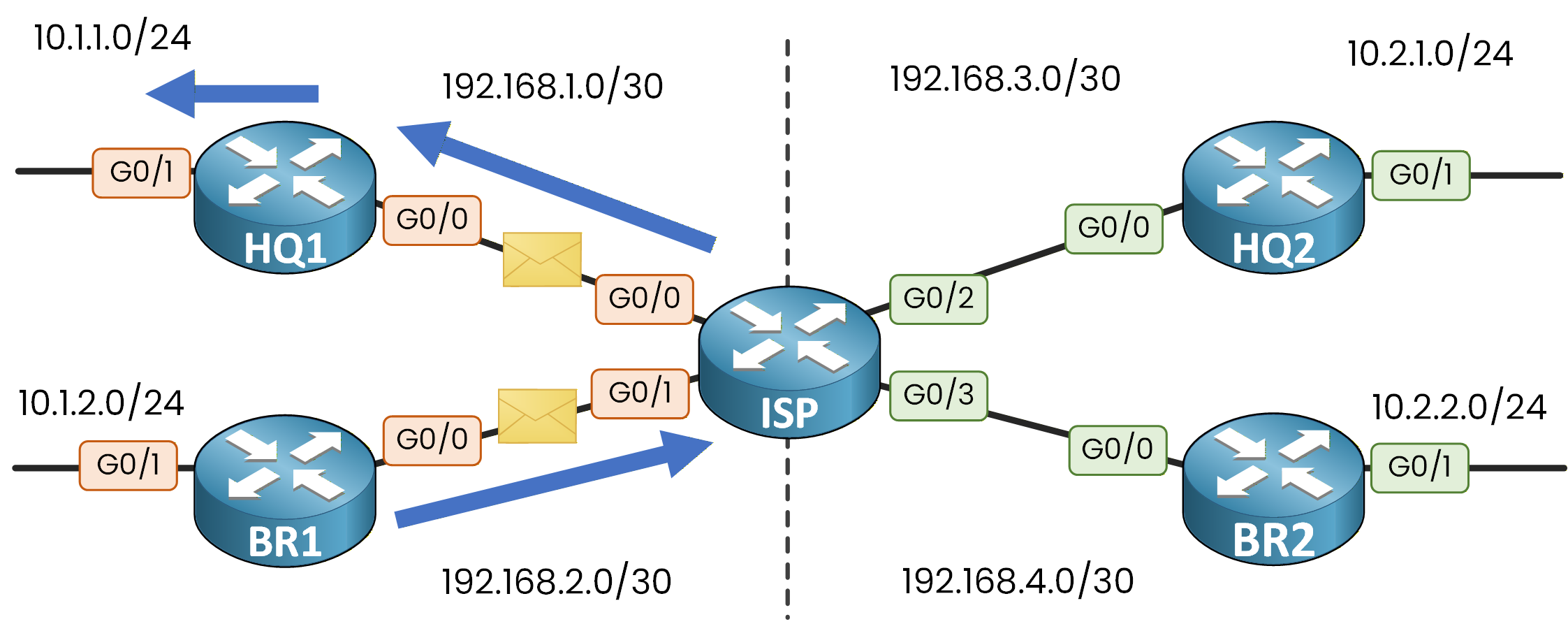
Figure 6 – Intra-VRF connectivity test
BR1# ping vrf CLIENT1 10.1.1.1 source 10.1.2.1
Type escape sequence to abort.
Sending 5, 100-byte ICMP Echos to 10.1.1.1, timeout is 2 seconds:
Packet sent with a source address of 10.1.2.1
!!!!!
Success rate is 100 percent (5/5), round-trip min/avg/max = 1/2/3 ms
CLIENT1 has full end-to-end connectivity between HQ1 and BR1 through your ISP.
Testing Inter-VRF Isolation
Now let's verify that the isolation actually works.
BR1 (VRF CLIENT1) tries to reach 10.2.1.1, which is HQ2's LAN behind VRF CLIENT2.
The packet is blocked at the ISP router because the destination does not exist in VRF CLIENT1's routing table.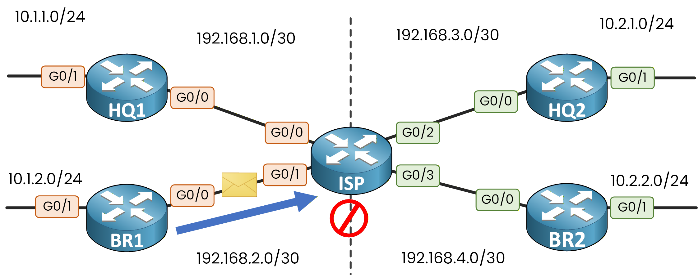
Figure 7 – Inter-VRF traffic blocked
BR1# ping vrf CLIENT1 10.2.1.1 source 10.1.2.1
Type escape sequence to abort.
Sending 5, 100-byte ICMP Echos to 10.2.1.1, timeout is 2 seconds:
Packet sent with a source address of 10.1.2.1
.....
Success rate is 0 percent (0/5)
This is the isolation working exactly as designed.
VRF CLIENT1 and VRF CLIENT2 are completely separate routing domains.Answer the question below
Which command tests connectivity to a destination inside a specific VRF?
Your VRFs are working. CLIENT1 traffic stays in CLIENT1, CLIENT2 traffic stays in CLIENT2.
But now you face a new problem.The Shared Service Problem
Your ISP has a shared DNS server at 10.0.99.10, connected to interface G0/4.
G0/4 has the IP address 10.0.99.1 and sits in the global routing table.Configure the DNS interface on the ISP router. This interface does not belong to any VRF:
ISP# conf t
Enter configuration commands, one per line.  End with CNTL/Z.
ISP(config)# interface G0/4
ISP(config-if)# ip address 10.0.99.1 255.255.255.0
ISP(config-if)# no shutdown
ISP(config-if)# end
Neither VRF CLIENT1 nor VRF CLIENT2 has a route to 10.0.99.0/24.
That network belongs to a different routing domain.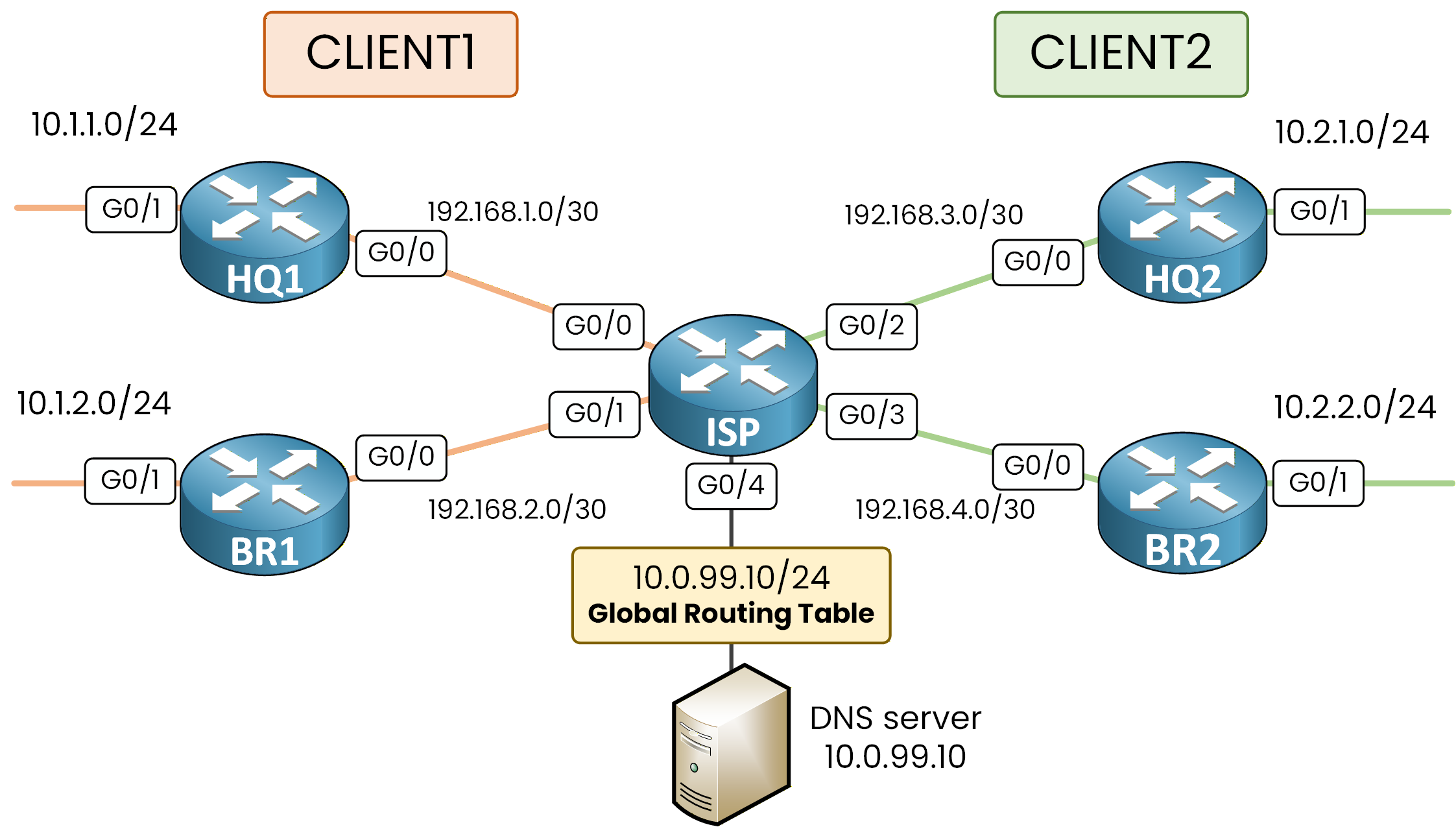
Figure 8 – DNS Server in the Global Routing Table
From BR1, try to reach the DNS server.
BR1# ping vrf CLIENT1 10.0.99.10 source 10.1.2.1
Type escape sequence to abort.
Sending 5, 100-byte ICMP Echos to 10.0.99.10, timeout is 2 seconds:
Packet sent with a source address of 10.1.2.1
.....
Success rate is 0 percent (0/5)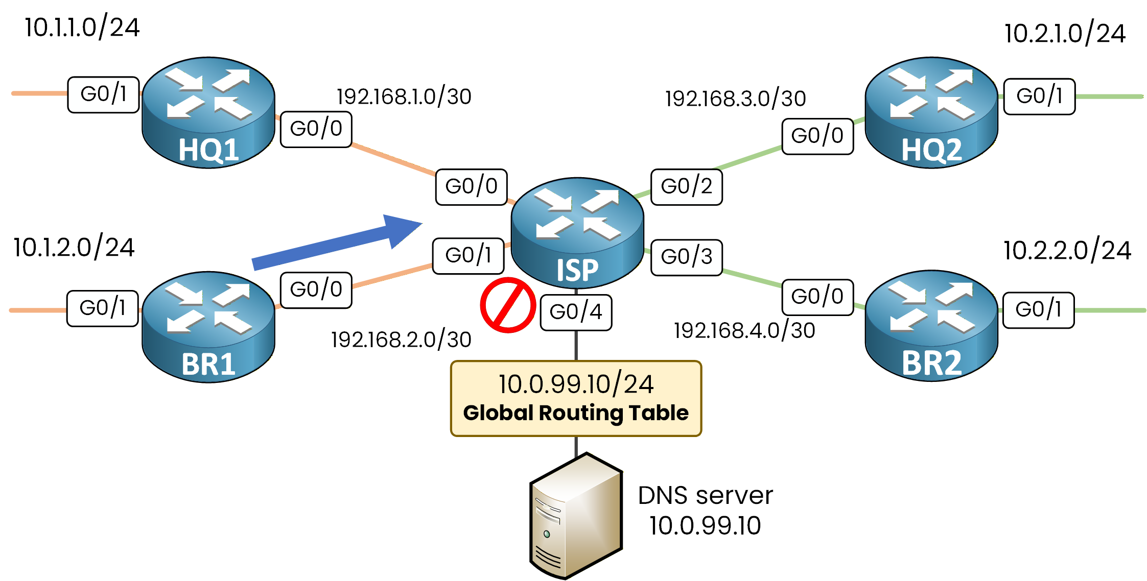
Figure 9 – DNS unreachable from CLIENT1 VRF
The ping fails because VRF CLIENT1 has no route to 10.0.99.0/24 in its VRF:
Answer the question below
Why can't VRF CLIENT1 reach the DNS server at 10.0.99.10?
Leaking Routes with the global Keyword
To give VRF CLIENT1 access to the DNS server, you need to "leak" a route from the global table into the VRF.
This is called inter-VRF route leaking.Let's walk through this with CLIENT1 (BR1). The same logic applies to CLIENT2.
Add a static route inside VRF CLIENT1 pointing to the DNS server through the global table:ISP# conf t Enter configuration commands, one per line. End with CNTL/Z. ISP(config)# ip route vrf CLIENT1 10.0.99.0 255.255.255.0 GigabitEthernet0/4 10.0.99.10 globalThe
globalkeyword tells the router: "this route belongs to the VRF, but resolve the next-hop in the global routing table."
Without it, the router looks for 10.0.99.10 inside the VRF, where it does not exist.The Return Path
Route leaking is not complete yet.
The DNS server can now receive requests from VRF CLIENT1.
But its replies go back into the global routing table, which has no route to the VRF subnets.You must add a return route in the global table pointing back to CLIENT1's networks through BR1:
ISP(config)# ip route 10.1.2.0 255.255.255.0 GigabitEthernet0/1 192.168.2.2
ISP(config)# end
This route covers the BR1 CLIENT1 subnet (10.1.2.0/24) and sends replies back through G0/1 toward BR1.
Now verify from BR1 that a CLIENT1 site can reach the shared DNS server through the route leak:
BR1# ping vrf CLIENT1 10.0.99.10 source 10.1.2.1
Type escape sequence to abort.
Sending 5, 100-byte ICMP Echos to 10.0.99.10, timeout is 2 seconds:
Packet sent with a source address of 10.1.2.1
!!!!!
Success rate is 100 percent (5/5), round-trip min/avg/max = 1/1/2 ms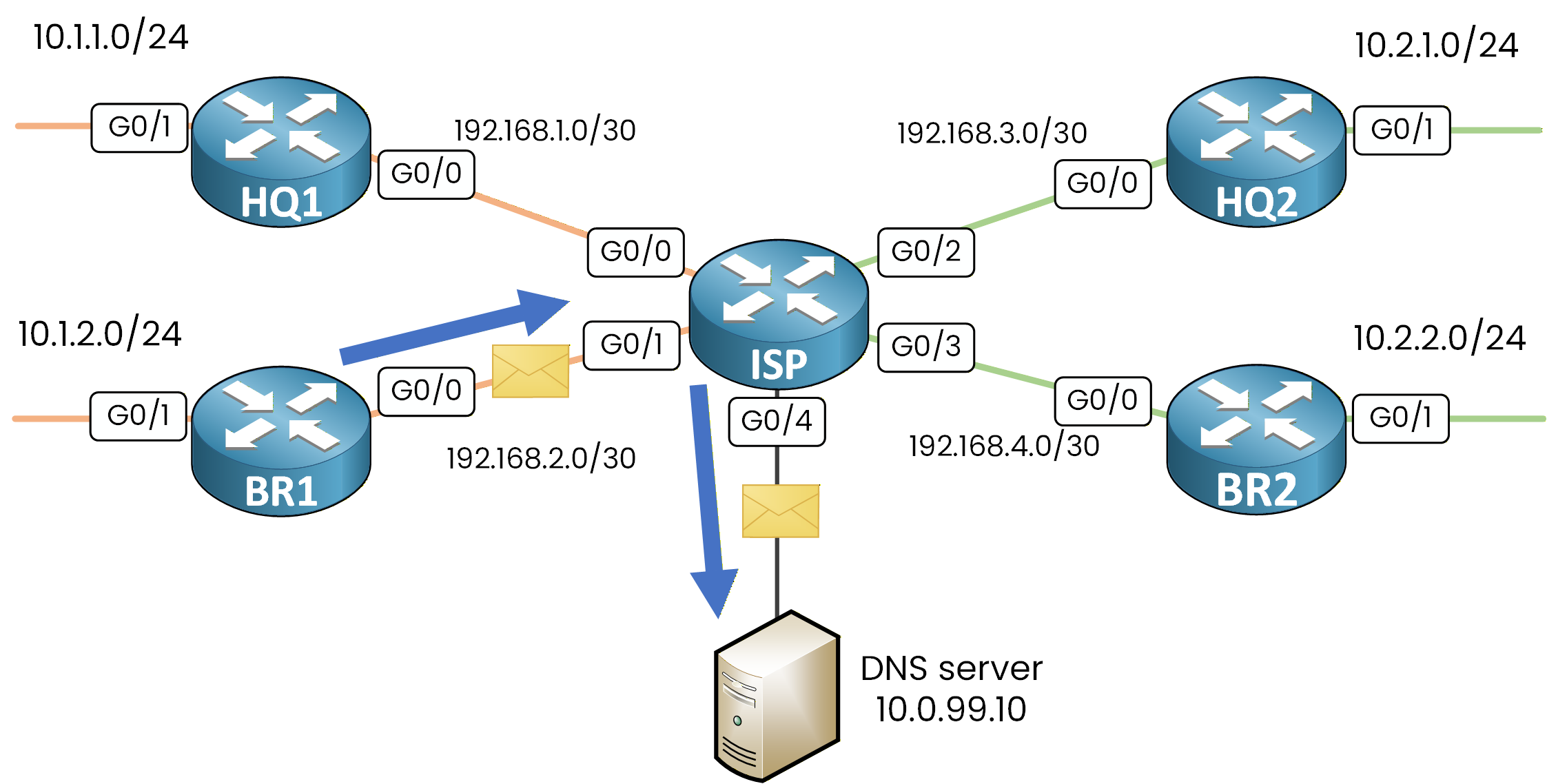
Figure 10 - Inter-VRF Route Leaking Traffic Succeeds
BR1 can now reach the shared DNS server from inside VRF CLIENT1, while remaining completely isolated from CLIENT2.
To give CLIENT2 the same access, you follow the exact same logic with a route leak and a return route for CLIENT2's subnets.Answer the question below
What keyword tells a static route to look up the next-hop in the global table instead of the VRF?