In a multi-area OSPF network, every non-backbone area must be directly connected to Area 0.
In our topology below, this rule is broken!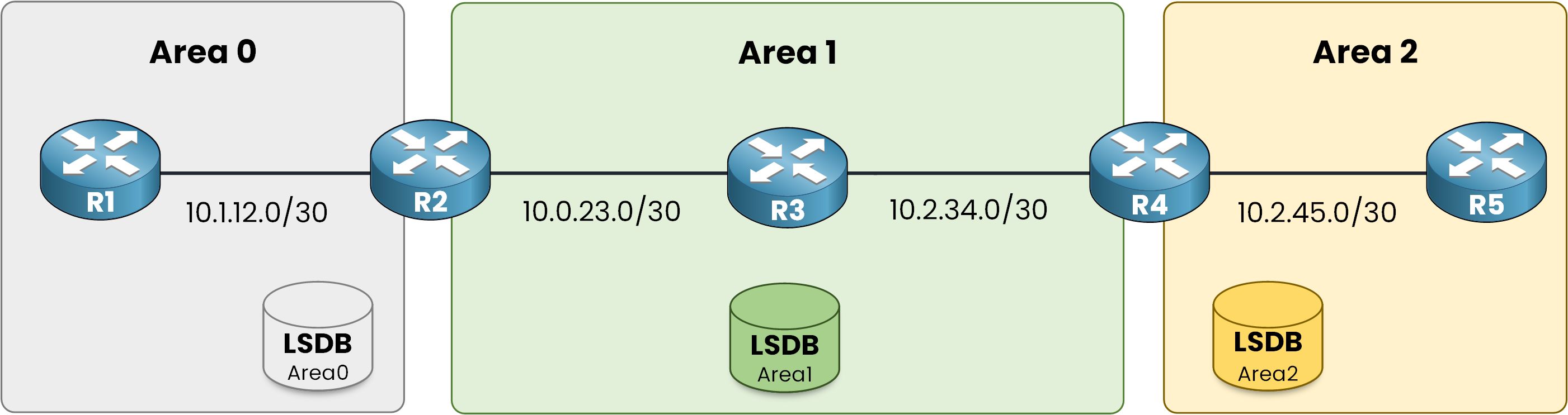
Figure 1 - OSPF Multi-Area Topology
As you can see, Area 2 is connected only to Area 1.
This creates a fundamental routing problem: inter-area traffic must always travel through the backbone (Area 0).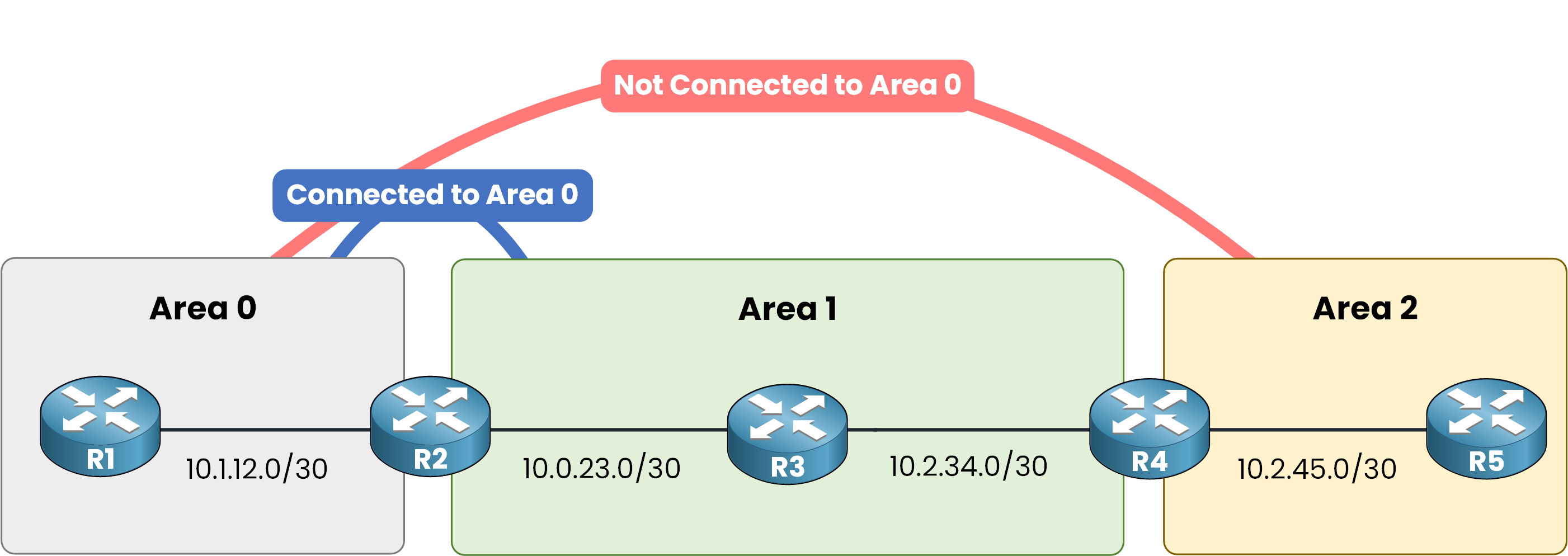
Figure 2 - Area 2 is not connected to Area 0
Because R4 has no active interface in Area 0, the networks of Area 2 can never be advertised into the backbone. The rest of the network will never learn them.
In this scenario, you can use an OSPF feature called a Virtual Link (VL) to resolve the issue without adding physical links. Let's take a look together.
Answer the question below
Which area is not connected to the backbone?
A Virtual Link (VL) is a logical tunnel used to connect a remote area (like Area 2) back to Area 0 across an intermediate area.
A Virtual Link is always configured between two ABRs. In our topology, R2 and R4 are the two ABRs.
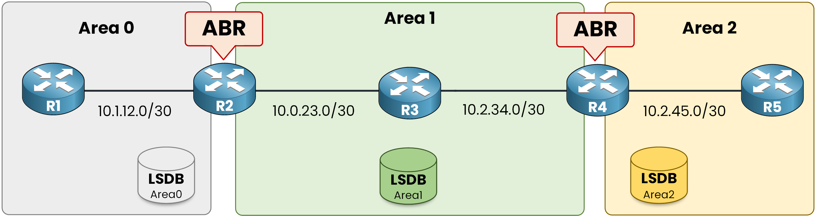
Figure 3 - R2 and R4 are the ABRs
The virtual link extends between R2 and R4; these two routers act as the Virtual Link Endpoints.
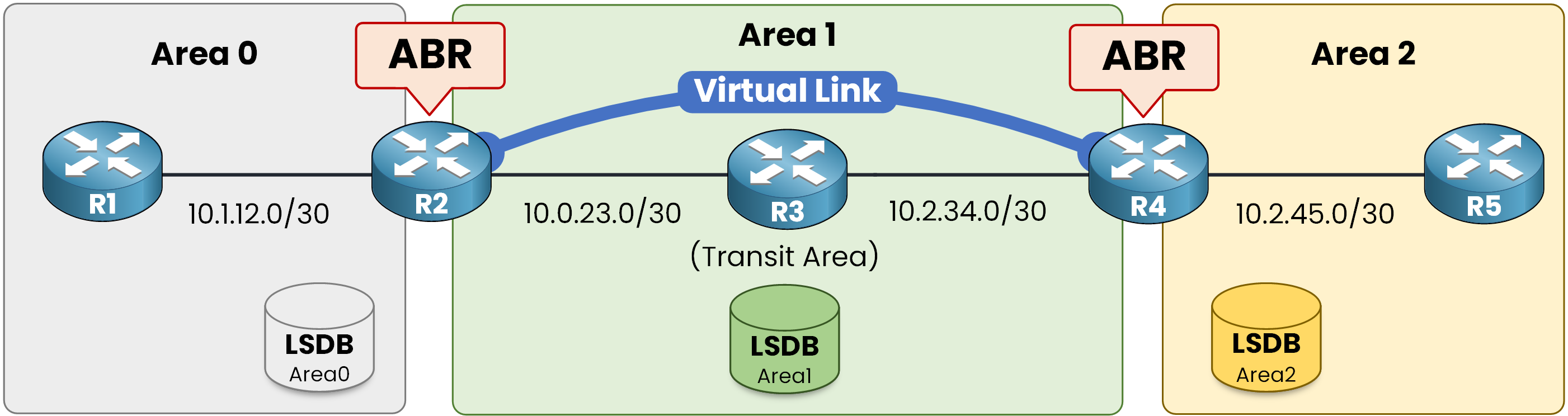
Figure 4 - The Virtual Link through the Transit Area
The tunnel crosses Area 1, which is designated as the Transit Area.
Through this logical connection, OSPF treats Area 2 as if it were directly connected to Area 0, satisfying the multi-area rule. Routing updates flow straight through the tunnel: the Type 3 LSAs carrying Area 2 networks are flooded directly into Area 0.
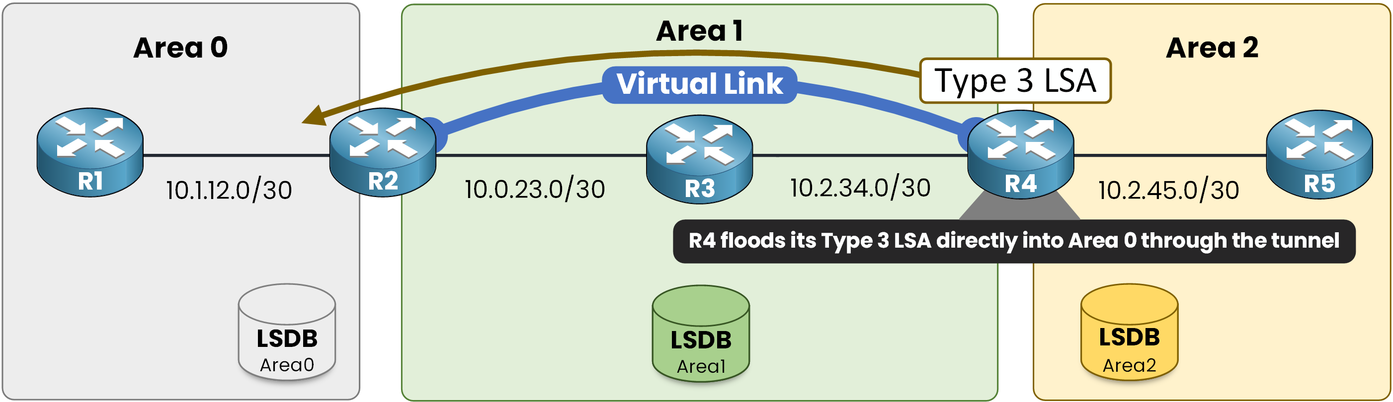
Figure 5 - The Type 3 LSA reaches Area 0 through the Virtual Link
Design Note: A Virtual Link is designed as a temporary patch. Treat it like duct tape, it restores full connectivity immediately while you plan a permanent physical topology fix, such as adding a direct physical link back to Area 0.
Answer the question below
A virtual link is always built between two ___.
Answer the question below
The area the virtual link crosses is called the _______ area.
Here is the complete topology along with interface roles and IP assignments:
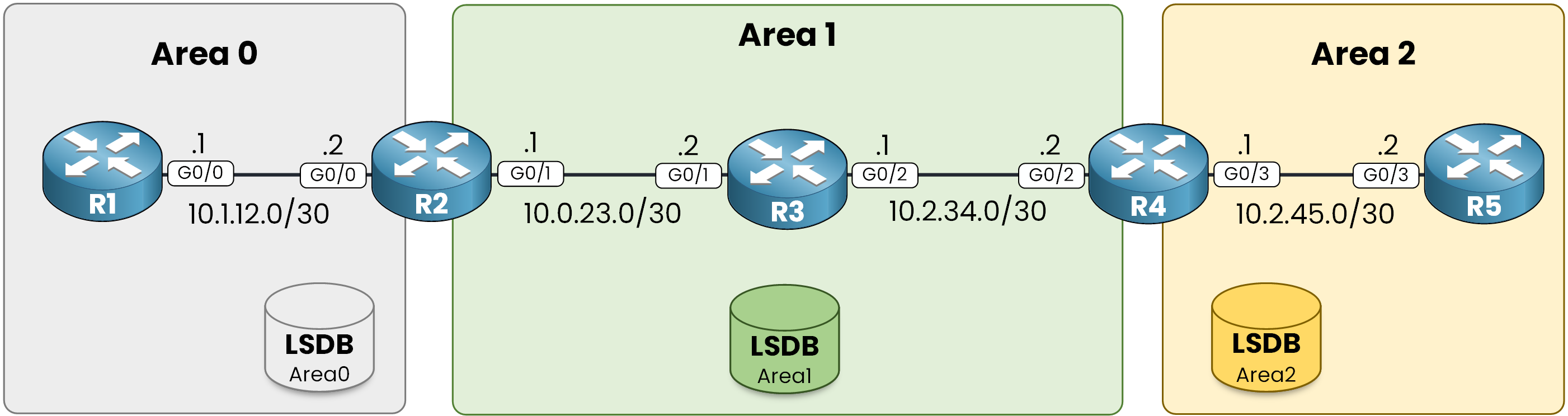
Figure 6 - Interfaces used in this lab
Step 1 – Configure the Interfaces
Go through the five routers (R1 to R5) and configure their respective IP addresses:
R1# configure terminal
R1(config)# interface g0/0
R1(config-if)# ip address 10.1.12.1 255.255.255.252
R1(config-if)# no shutdown
R1(config-if)# end
R2 sits at the border between Area 0 and Area 1:
R2# configure terminal
R2(config)# interface g0/0
R2(config-if)# ip address 10.1.12.2 255.255.255.252
R2(config-if)# no shutdown

R2(config-if)# interface g0/1
R2(config-if)# ip address 10.0.23.1 255.255.255.252
R2(config-if)# no shutdown
R2(config-if)# end
Configure R3 in the middle of Area 1:
R3# configure terminal
R3(config)# interface g0/1
R3(config-if)# ip address 10.0.23.2 255.255.255.252
R3(config-if)# no shutdown

R3(config-if)# interface g0/2
R3(config-if)# ip address 10.2.34.1 255.255.255.252
R3(config-if)# no shutdown
R3(config-if)# end
Configure R4 at the border between Area 1 and Area 2:
R4# configure terminal
R4(config)# interface g0/2
R4(config-if)# ip address 10.2.34.2 255.255.255.252
R4(config-if)# no shutdown

R4(config-if)# interface g0/3
R4(config-if)# ip address 10.2.45.1 255.255.255.252
R4(config-if)# no shutdown
R4(config-if)# end
Finish with R5 inside Area 2:
R5# configure terminal
R5(config)# interface g0/3
R5(config-if)# ip address 10.2.45.2 255.255.255.252
R5(config-if)# no shutdown
R5(config-if)# end
Every link is up and addressed. All routers can reach their immediate neighbors, but OSPF routing is not yet enabled.
Step 2 – Enable OSPF
Now, initialize the OSPF routing process across the domain:
Figure 7 - Lab Topology
Start the process on R1, assign its Router ID, and advertise its network:
R1# configure terminal
R1(config)# router ospf 1
R1(config-router)# router-id 1.1.1.1
R1(config-router)# network 10.1.12.0 0.0.0.3 area 0
R1(config-router)# end
Move to R2. Because it shares the
10.1.12.0/30link with R1, watch what happens right after the first network command:R2# configure terminal R2(config)# router ospf 1 R2(config-router)# router-id 2.2.2.2 R2(config-router)# network 10.1.12.0 0.0.0.3 area 0 %OSPF-5-ADJCHG: Process 1, Nbr 1.1.1.1 on GigabitEthernet0/0 from LOADING to FULL, Loading Done R2(config-router)# network 10.0.23.0 0.0.0.3 area 1 R2(config-router)# endThe adjacency with R1 comes up the moment the link is advertised.
Same routine on the next three routers: each one goes FULL with its left neighbor as soon as the shared network enters OSPF.
R3# configure terminal
R3(config)# router ospf 1
R3(config-router)# router-id 3.3.3.3
R3(config-router)# network 10.0.23.0 0.0.0.3 area 1
%OSPF-5-ADJCHG: Process 1, Nbr 2.2.2.2 on GigabitEthernet0/1 from LOADING to FULL, Loading Done
R3(config-router)# network 10.2.34.0 0.0.0.3 area 1
R3(config-router)# end
Now R4, the border router of Area 2.
R4# configure terminal
R4(config)# router ospf 1
R4(config-router)# router-id 4.4.4.4
R4(config-router)# network 10.2.34.0 0.0.0.3 area 1
%OSPF-5-ADJCHG: Process 1, Nbr 3.3.3.3 on GigabitEthernet0/2 from LOADING to FULL, Loading Done
R4(config-router)# network 10.2.45.0 0.0.0.3 area 2
R4(config-router)# end
Finish with R5.
R5# configure terminal
R5(config)# router ospf 1
R5(config-router)# router-id 5.5.5.5
R5(config-router)# network 10.2.45.0 0.0.0.3 area 2
%OSPF-5-ADJCHG: Process 1, Nbr 4.4.4.4 on GigabitEthernet0/3 from LOADING to FULL, Loading Done
R5(config-router)# end
Four adjacencies, all
FULL. Every router is talking to its neighbors. And yet, the network is broken.Step 3 – Identify the Problem
Start on R1 and look at what OSPF installed in the routing table:
R1# show ip route ospf | begin Gateway

Gateway of last resort is not set

      10.0.0.0/8 is variably subnetted, 4 subnets, 2 masks
O IA     10.0.23.0/30 [110/2] via 10.1.12.2, 00:12:40, GigabitEthernet0/0
O IA     10.2.34.0/30 [110/3] via 10.1.12.2, 00:12:40, GigabitEthernet0/0
You can see
10.0.23.0/30and10.2.34.0/30, the networks of Area 1. But the network of Area 2 is missing:10.2.45.0/30is nowhere in the table.This is the moment you decide to configure a virtual link to fix the problem.
Answer the question below
Click 'Complete' to continue
Step 4 – Identify Endpoint Router IDs
A virtual link always runs between the two ABRs of the transit area. In our case: R2 and R4.
To configure it, you need their Router IDs. Grab them first.Check R2:
R2# show ip ospf | include ID
 Routing Process "ospf 1" with ID 2.2.2.2
Same check on R4:
R4# show ip ospf | include ID
 Routing Process "ospf 1" with ID 4.4.4.4
Step 5 – Configure the Virtual Link
On R2, point the virtual link at the Router ID of R4:
R2# configure terminal
R2(config)# router ospf 1
R2(config-router)# area 1 virtual-link 4.4.4.4
R2(config-router)# end
Configuration Note:
4.4.4.4is the Router ID of R4, not an IP address of one of its interfaces. This is the most common virtual link mistake.Same command on the other side, pointing back at the Router ID of R2:
R4# configure terminal
R4(config)# router ospf 1
R4(config-router)# area 1 virtual-link 2.2.2.2
%OSPF-5-ADJCHG: Process 1, Nbr 2.2.2.2 on OSPF_VL0 from LOADING to FULL, Loading Done
R4(config-router)# end
As soon as the second side is configured, a new adjacency comes up. It lives on interface
OSPF_VL0.Step 6 – Verify the Virtual Link Status & Routing Table
One command tells you everything about the virtual link:
R2# show ip ospf virtual-links

Virtual Link OSPF_VL0 to router 4.4.4.4 is up
  Run as demand circuit
  DoNotAge LSA allowed.
  Transit area 1, via interface GigabitEthernet0/1
 Topology-MTID    Cost    Disabled     Shutdown      Topology Name
        0           2        no           no            Base
  Transmit Delay is 1 sec, State POINT_TO_POINT,
  Timer intervals configured, Hello 10, Dead 40, Wait 40, Retransmit 5
    Hello due in 00:00:01
    Adjacency State FULL (Hello suppressed)
Two checks matter: the link is up and the adjacency is FULL. The cost of 2 is the sum of the two hops through the transit area: R2 to R3, then R3 to R4.
Now look at the neighbor table of R2:
R2# show ip ospf neighbor

Neighbor ID     Pri   State           Dead Time   Address         Interface
4.4.4.4           0   FULL/  -        -           10.2.34.2       OSPF_VL0
1.1.1.1           1   FULL/BDR        00:00:33    10.1.12.1       GigabitEthernet0/0
3.3.3.3           1   FULL/DR         00:00:38    10.0.23.2       GigabitEthernet0/1
R2 is
FULLwith R4, a router it is not physically connected to.
The Dead Time shows-because Hellos are suppressed on a virtual link.The virtual link even shows up as an interface. Look at which area it belongs to:
R2# show ip ospf interface brief Interface PID Area IP Address/Mask Cost State Nbrs F/C Gi0/0 1 0 10.1.12.2/30 1 DR 1/1 VL0 1 0 10.0.23.1/30 2 P2P 1/1 Gi0/1 1 1 10.0.23.1/30 1 BDR 1/1VL0sits in Area 0, stateP2P.
The virtual link is a backbone interface: Area 0 now extends all the way to R4.Back to R1, the router where the problem started:
R1# show ip route ospf | begin Gateway Gateway of last resort is not set 10.0.0.0/8 is variably subnetted, 5 subnets, 2 masks O IA 10.0.23.0/30 [110/2] via 10.1.12.2, 00:25:12, GigabitEthernet0/0 O IA 10.2.34.0/30 [110/3] via 10.1.12.2, 00:25:12, GigabitEthernet0/0 O IA 10.2.45.0/30 [110/4] via 10.1.12.2, 00:02:03, GigabitEthernet0/010.2.45.0/30, the network of Area 2, is finally in the routing table of R1.One more check. How does the virtual link appear in the database itself?
R2# show ip ospf database

            OSPF Router with ID (2.2.2.2) (Process ID 1)

                Router Link States (Area 0)

Link ID         ADV Router      Age         Seq#       Checksum Link count
1.1.1.1         1.1.1.1         412         0x8000000A 0x00A1B2 1
2.2.2.2         2.2.2.2         408         0x8000000C 0x00C3D4 2
4.4.4.4         4.4.4.4         1     (DNA) 0x80000003 0x00E5F6 1
R4 now advertises a Router LSA inside Area 0, carried by the virtual link.
The(DNA)flag means Do Not Age: LSAs crossing a virtual link never expire, so they don't need periodic refresh.Step 7 – End-to-End Testing
We can verify connectivity from R1 to the R5 interface IP address in Area 2:
R1# ping 10.2.45.2

Type escape sequence to abort.
Sending 5, 100-byte ICMP Echos to 10.2.45.2, timeout is 2 seconds:
!!!!!
Success rate is 100 percent (5/5), round-trip min/avg/max = 1/2/4 ms
R1 reaches a network that did not exist in its routing table a few minutes ago.
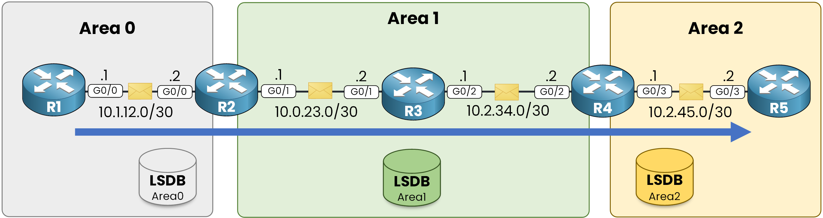
Figure 8 - The packet travels from R1 to R5
The virtual link did not add a single cable. It added a logical Area 0 adjacency, and OSPF did the rest.
Answer the question below
In the virtual-link command, do you configure the neighbor's IP address or router ID?
Before you finish, launch this scenario to verify your understanding.
Complete the interactive lab, obtain your flag, and use it to answer the question below.Answer the question below
What is the flag?