Now that you understand why GRE is used, we can build the tunnel.
In this lab, R1 and R2 are connected through two ISP routers across the Internet.
The Internet acts as the underlay network, while the GRE tunnel will create the overlay connection between the two sites.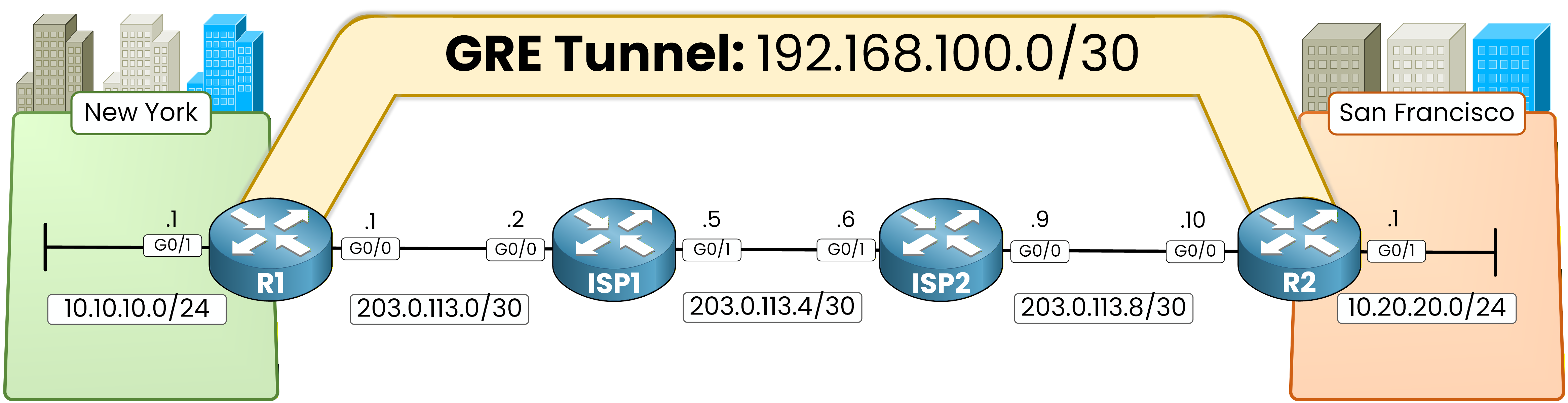
Figure 1 - GRE lab topology
Before creating the GRE tunnel, the underlay network must be working correctly.
This means the ISP routers must be able to route traffic between the tunnel endpoints.First, configure static routes on the ISP routers so they can forward traffic between the tunnel endpoints.
This ensures the underlay network can reach the GRE tunnel endpoints.ISP1 Static Routing

Figure 2 - ISP1 static routing
ISP1 must know how to reach the remote WAN link behind ISP2.
On ISP1, configure the following static route:ISP1# conf t Enter configuration commands, one per line. End with CNTL/Z. ISP1(config)# ip route 203.0.113.8 255.255.255.252 203.0.113.6This route allows ISP1 to forward traffic toward the remote WAN subnet behind ISP2.
ISP2 Static Routing
ISP2 must also know how to reach the remote WAN link behind ISP1.

Figure 3 - ISP2 static routing
Configure the following route on ISP2:
ISP2# conf t
Enter configuration commands, one per line.  End with CNTL/Z.
ISP2(config)# ip route 203.0.113.0 255.255.255.252 203.0.113.5
At this stage, the underlay network can route traffic between R1 and R2.
Configure Default Route
Each enterprise router must also have a default route pointing toward the ISP.

Figure 4 - Default route configuration
On R1:
R1(config)# ip route 0.0.0.0 0.0.0.0 203.0.113.2On R2:
R2(config)# ip route 0.0.0.0 0.0.0.0 203.0.113.9These routes ensure that Internet-bound traffic is forwarded to the ISP routers.
Answer the question below
What is the next hop of the default route configured on R1?
GRE Tunnel Configuration
Now we can create the GRE tunnel between R1 and R2.
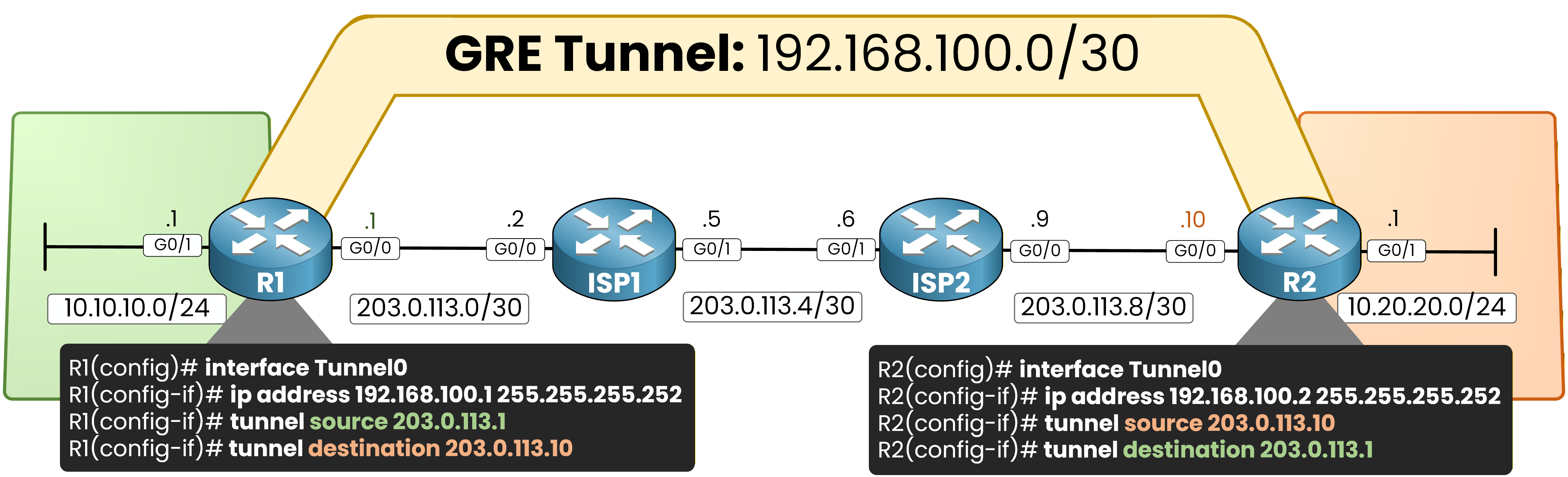
Figure 5 - GRE tunnel configuration
On R1:
R1(config)# int tunnel0
%LINEPROTO-5-UPDOWN: Line protocol on Interface Tunnel0, changed state to down
R1(config-if)# ip address 192.168.100.1 255.255.255.252
R1(config-if)# tunnel source 203.0.113.1
R1(config-if)# tunnel destination 203.0.113.10
%LINEPROTO-5-UPDOWN: Line protocol on Interface Tunnel0, changed state to up
R1(config-if)# end
On R2:
R2(config)# int tunnel0
%LINEPROTO-5-UPDOWN: Line protocol on Interface Tunnel0, changed state to down
R2(config-if)# ip address 192.168.100.2 255.255.255.252
R2(config-if)# tunnel source 203.0.113.10
R2(config-if)# tunnel destination 203.0.113.1
%LINEPROTO-5-UPDOWN: Line protocol on Interface Tunnel0, changed state to up
%OSPF-5-ADJCHG: Process 1, Nbr 1.1.1.1 on Tunnel0 from LOADING to FULL, Loading Done
R2(config-if)# end
This configuration creates a GRE tunnel between R1 and R2 using the Internet as the transport network.
Once the tunnel is established, OSPF forms an adjacency and exchanges routes between the sites.OSPF over GRE
Once the tunnel is created, we will run OSPF across the GRE tunnel so the routers can exchange routes dynamically.
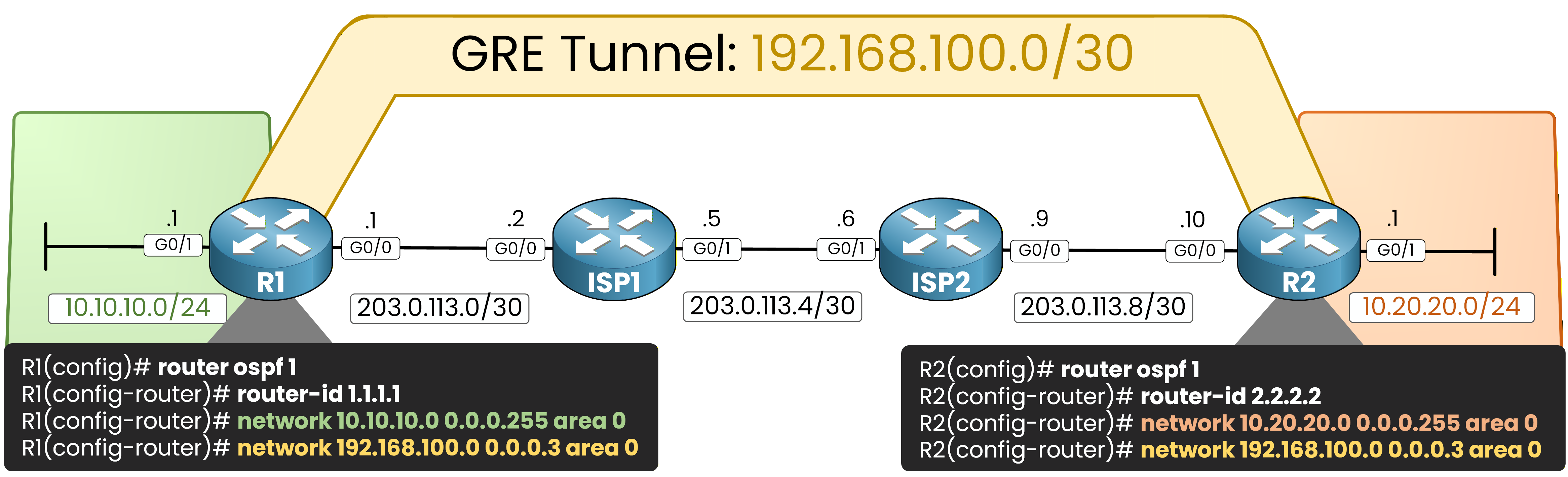
Figure 6 - OSPF over GRE
On R1:
R1(config)# router ospf 1
R1(config-router)# router-id 1.1.1.1
R1(config-router)# network 10.10.10.0 0.0.0.255 area 0
R1(config-router)# network 192.168.100.0 0.0.0.3 area 0
R1(config-router)# exit
On R2:
R2(config)# router ospf 1
R2(config-router)# router-id 2.2.2.2
R2(config-router)# network 10.20.20.0 0.0.0.255 area 0
R2(config-router)# network 192.168.100.0 0.0.0.3 area 0
R2(config-router)# exit
OSPF will run across the tunnel network (192.168.100.0/30) and allow both routers to learn each other’s LAN networks.
Answer the question below
Which routing protocol is used across the GRE tunnel to exchange routes between R1 and R2?
Now it’s time to verify that the GRE tunnel is working correctly.
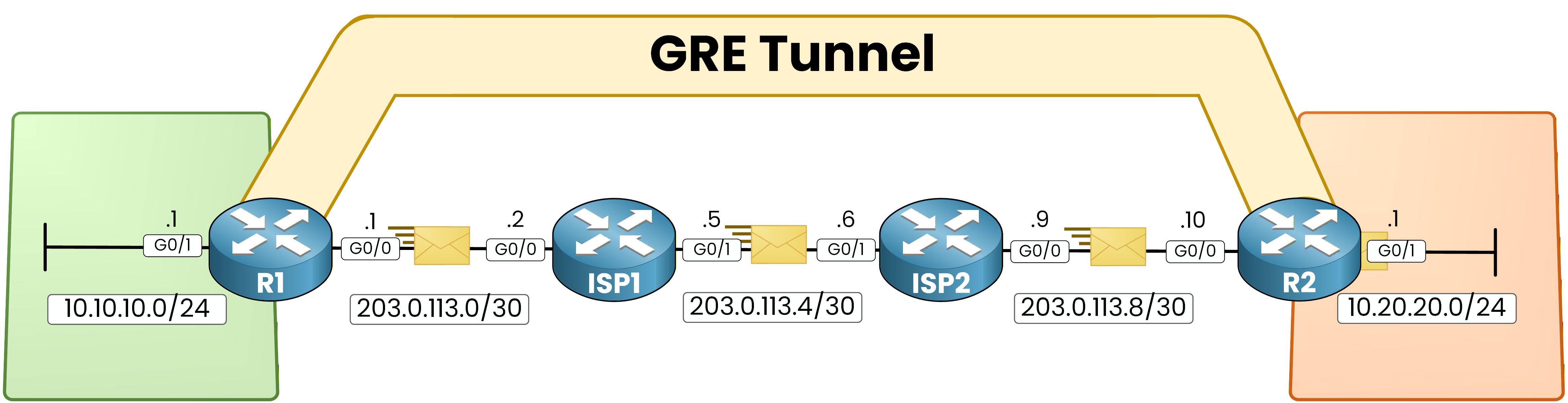
Figure 7 - GRE traffic encapsulation
Connectivity Test
First, test connectivity from R1 to the LAN behind R2.
R1# ping 10.20.20.1
Type escape sequence to abort.
Sending 5, 100-byte ICMP Echos to 10.20.20.1, timeout is 2 seconds:
!!!!!
Success rate is 100 percent (5/5), round-trip min/avg/max = 3/4/5 ms
If the GRE tunnel is working correctly, the ping should succeed.
Next, run a traceroute to see the path used by the packet.R1# traceroute 10.20.20.1 Type escape sequence to abort. Tracing the route to 10.20.20.1 VRF info: (vrf in name/id, vrf out name/id) 1 192.168.100.2 6 msec 6 msec *Notice that the traceroute shows only the tunnel endpoint.
The ISP routers are not visible because the packet is encapsulated inside the GRE tunnel.
You can perform the same tests from R2 toward the network behind R1.R2# ping 10.10.10.1 Type escape sequence to abort. Sending 5, 100-byte ICMP Echos to 10.10.10.1, timeout is 2 seconds: !!!!! Success rate is 100 percent (5/5), round-trip min/avg/max = 2/2/4 msR2# traceroute 10.10.10.1 Type escape sequence to abort. Tracing the route to 10.10.10.1 VRF info: (vrf in name/id, vrf out name/id) 1 192.168.100.1 5 msec 23 msec *The packet appears to travel directly between the two routers.
Answer the question below
Which address appears as the only hop in the traceroute from R1 to 10.20.20.1?
Verify Tunnel Interface
You can verify that the GRE tunnel interface is operational.
Run the following command on R1:R1# show interfaces tunnel0 Tunnel0 is up, line protocol is up Hardware is Tunnel Internet address is 192.168.100.1/30 MTU 17916 bytes, BW 100 Kbit/sec, DLY 50000 usec, reliability 255/255, txload 1/255, rxload 1/255 Encapsulation TUNNEL, loopback not set Keepalive not set Tunnel linestate evaluation up Tunnel source 203.0.113.1, destination 203.0.113.10 Tunnel protocol/transport GRE/IP Key disabled, sequencing disabled Checksumming of packets disabled Tunnel TTL 255, Fast tunneling enabled Tunnel transport MTU 1476 bytes Tunnel transmit bandwidth 8000 (kbps) Tunnel receive bandwidth 8000 (kbps) Last input 00:00:08, output 00:00:04, output hang never Last clearing of "show interface" counters 00:02:22 Input queue: 0/75/0/0 (size/max/drops/flushes); Total output drops: 0 Queueing strategy: fifo Output queue: 0/0 (size/max) 5 minute input rate 0 bits/sec, 0 packets/sec 5 minute output rate 0 bits/sec, 0 packets/sec 13 packets input, 1368 bytes, 0 no buffer Received 0 broadcasts (0 IP multicasts) 0 runts, 0 giants, 0 throttles 0 input errors, 0 CRC, 0 frame, 0 overrun, 0 ignored, 0 abort 19 packets output, 1972 bytes, 0 underruns 0 output errors, 0 collisions, 0 interface resets 0 unknown protocol drops 0 output buffer failures, 0 output buffers swapped outIn the output, focus on the following information:
Tunnel0 is up, line protocol is up → confirms that the tunnel is operational
Tunnel source 203.0.113.1, destination 203.0.113.10 → shows the tunnel endpoints
Tunnel protocol/transport GRE/IP → confirms that the interface is using GRE encapsulation
You should see the same status on R2:
R2# show interfaces tunnel0
Tunnel0 is up, line protocol is up
  Hardware is Tunnel
  Internet address is 192.168.100.2/30
  MTU 17916 bytes, BW 100 Kbit/sec, DLY 50000 usec,
     reliability 255/255, txload 1/255, rxload 1/255
  Encapsulation TUNNEL, loopback not set
  Keepalive not set
  Tunnel linestate evaluation up
  Tunnel source 203.0.113.10, destination 203.0.113.1
  Tunnel protocol/transport GRE/IP
    Key disabled, sequencing disabled
    Checksumming of packets disabled
  Tunnel TTL 255, Fast tunneling enabled
  Tunnel transport MTU 1476 bytes
  Tunnel transmit bandwidth 8000 (kbps)
  Tunnel receive bandwidth 8000 (kbps)
  Last input 00:00:04, output 00:00:08, output hang never
  Last clearing of "show interface" counters 00:02:27
  Input queue: 0/75/0/0 (size/max/drops/flushes); Total output drops: 0
  Queueing strategy: fifo
  Output queue: 0/0 (size/max)
  5 minute input rate 0 bits/sec, 0 packets/sec
  5 minute output rate 0 bits/sec, 0 packets/sec
     20 packets input, 2096 bytes, 0 no buffer
     Received 0 broadcasts (0 IP multicasts)
     0 runts, 0 giants, 0 throttles
     0 input errors, 0 CRC, 0 frame, 0 overrun, 0 ignored, 0 abort
     19 packets output, 1992 bytes, 0 underruns
     0 output errors, 0 collisions, 0 interface resets
     0 unknown protocol drops
     0 output buffer failures, 0 output buffers swapped out
This confirms that the GRE tunnel is established between the routers.
Answer the question below
What encapsulation protocol is used by the tunnel interface?
Verify OSPF Neighbor
Next, verify that OSPF formed a neighbor adjacency through the tunnel.
On R1, run:R1# show ip ospf neighbor Neighbor ID Pri State Dead Time Address Interface 2.2.2.2 0 FULL/ - 00:00:34 192.168.100.2 Tunnel0In the output, focus on:
Neighbor ID 2.2.2.2
State FULL
Interface Tunnel0
This shows that R1 formed an OSPF adjacency with R2 through the GRE tunnel.
Run the same command on R2:R2# show ip ospf neighbor Neighbor ID Pri State Dead Time Address Interface 1.1.1.1 0 FULL/ - 00:00:37 192.168.100.1 Tunnel0You should see:
Neighbor ID 1.1.1.1
State FULL
Interface Tunnel0
The FULL state confirms that the OSPF adjacency is fully established.
Verify Routing Table
Next, verify that the routers learned the remote LAN networks through OSPF.
On R1, run:R1# show ip route Codes: L - local, C - connected, S - static, R - RIP, M - mobile, B - BGP D - EIGRP, EX - EIGRP external, O - OSPF, IA - OSPF inter area N1 - OSPF NSSA external type 1, N2 - OSPF NSSA external type 2 E1 - OSPF external type 1, E2 - OSPF external type 2 i - IS-IS, su - IS-IS summary, L1 - IS-IS level-1, L2 - IS-IS level-2 ia - IS-IS inter area, * - candidate default, U - per-user static route o - ODR, P - periodic downloaded static route, H - NHRP, l - LISP a - application route + - replicated route, % - next hop override, p - overrides from PfR Gateway of last resort is 203.0.113.2 to network 0.0.0.0 S* 0.0.0.0/0 [1/0] via 203.0.113.2 10.0.0.0/8 is variably subnetted, 3 subnets, 2 masks C 10.10.10.0/24 is directly connected, GigabitEthernet0/1 L 10.10.10.1/32 is directly connected, GigabitEthernet0/1 O 10.20.20.0/24 [110/1001] via 192.168.100.2, 00:04:03, Tunnel0 192.168.100.0/24 is variably subnetted, 2 subnets, 2 masks C 192.168.100.0/30 is directly connected, Tunnel0 L 192.168.100.1/32 is directly connected, Tunnel0 203.0.113.0/24 is variably subnetted, 2 subnets, 2 masks C 203.0.113.0/30 is directly connected, GigabitEthernet0/0 L 203.0.113.1/32 is directly connected, GigabitEthernet0/0O → the route was learned through OSPF
192.168.100.2 → the next hop is the remote tunnel endpoint
Tunnel0 → the traffic will be forwarded through the GRE tunnel
This confirms that R1 learned the San Francisco network through the tunnel.
Now check the routing table on R2:
R2# show ip route
Codes: L - local, C - connected, S - static, R - RIP, M - mobile, B - BGP
       D - EIGRP, EX - EIGRP external, O - OSPF, IA - OSPF inter area
       N1 - OSPF NSSA external type 1, N2 - OSPF NSSA external type 2
       E1 - OSPF external type 1, E2 - OSPF external type 2
       i - IS-IS, su - IS-IS summary, L1 - IS-IS level-1, L2 - IS-IS level-2
       ia - IS-IS inter area, * - candidate default, U - per-user static route
       o - ODR, P - periodic downloaded static route, H - NHRP, l - LISP
       a - application route
       + - replicated route, % - next hop override, p - overrides from PfR

Gateway of last resort is 203.0.113.9 to network 0.0.0.0

S*    0.0.0.0/0 [1/0] via 203.0.113.9
      10.0.0.0/8 is variably subnetted, 3 subnets, 2 masks
O        10.10.10.0/24 [110/1001] via 192.168.100.1, 00:04:36, Tunnel0
C        10.20.20.0/24 is directly connected, GigabitEthernet0/1
L        10.20.20.1/32 is directly connected, GigabitEthernet0/1
      192.168.100.0/24 is variably subnetted, 2 subnets, 2 masks
C        192.168.100.0/30 is directly connected, Tunnel0
L        192.168.100.2/32 is directly connected, Tunnel0
      203.0.113.0/24 is variably subnetted, 2 subnets, 2 masks
C        203.0.113.8/30 is directly connected, GigabitEthernet0/0
L        203.0.113.10/32 is directly connected, GigabitEthernet0/0
This shows that R2 learned the New York network through the GRE tunnel.
At this point, routing information is successfully exchanged across the overlay network.Answer the question below
What is the next-hop IP used by R1 to reach the 10.20.20.0/24 network?
Verify Tunnel Traffic
Finally, verify that traffic is actually passing through the GRE tunnel.
Start by checking the current tunnel statistics on R1:R1# show interfaces tunnel0 Tunnel0 is up, line protocol is up Hardware is Tunnel Internet address is 192.168.100.1/30 MTU 17916 bytes, BW 100 Kbit/sec, DLY 50000 usec, reliability 255/255, txload 1/255, rxload 1/255 Encapsulation TUNNEL, loopback not set Keepalive not set Tunnel linestate evaluation up Tunnel source 203.0.113.1, destination 203.0.113.10 Tunnel protocol/transport GRE/IP Key disabled, sequencing disabled Checksumming of packets disabled Tunnel TTL 255, Fast tunneling enabled Tunnel transport MTU 1476 bytes Tunnel transmit bandwidth 8000 (kbps) Tunnel receive bandwidth 8000 (kbps) Last input 00:00:01, output 00:00:01, output hang never Last clearing of "show interface" counters 00:17:06 Input queue: 0/75/0/0 (size/max/drops/flushes); Total output drops: 0 Queueing strategy: fifo Output queue: 0/0 (size/max) 5 minute input rate 0 bits/sec, 0 packets/sec 5 minute output rate 0 bits/sec, 0 packets/sec 130 packets input, 13427 bytes, 0 no buffer Received 0 broadcasts (0 IP multicasts) 0 runts, 0 giants, 0 throttles 0 input errors, 0 CRC, 0 frame, 0 overrun, 0 ignored, 0 abort 142 packets output, 14490 bytes, 0 underruns 0 output errors, 0 collisions, 0 interface resets 0 unknown protocol drops 0 output buffer failures, 0 output buffers swapped outFocus on the packet counters:
130 packets input
142 packets output
Now generate traffic across the tunnel:
R1# ping 10.20.20.1
Type escape sequence to abort.
Sending 5, 100-byte ICMP Echos to 10.20.20.1, timeout is 2 seconds:
!!!!!
Success rate is 100 percent (5/5), round-trip min/avg/max = 3/4/5 ms
If the tunnel is working correctly, the ping should succeed.
After generating traffic, check the tunnel interface again:R1# show interfaces tunnel0 Tunnel0 is up, line protocol is up Hardware is Tunnel Internet address is 192.168.100.1/30 MTU 17916 bytes, BW 100 Kbit/sec, DLY 50000 usec, reliability 255/255, txload 1/255, rxload 1/255 Encapsulation TUNNEL, loopback not set Keepalive not set Tunnel linestate evaluation up Tunnel source 203.0.113.1, destination 203.0.113.10 Tunnel protocol/transport GRE/IP Key disabled, sequencing disabled Checksumming of packets disabled Tunnel TTL 255, Fast tunneling enabled Tunnel transport MTU 1476 bytes Tunnel transmit bandwidth 8000 (kbps) Tunnel receive bandwidth 8000 (kbps) Last input 00:00:00, output 00:00:00, output hang never Last clearing of "show interface" counters 00:17:14 Input queue: 0/75/0/0 (size/max/drops/flushes); Total output drops: 0 Queueing strategy: fifo Output queue: 0/0 (size/max) 5 minute input rate 0 bits/sec, 0 packets/sec 5 minute output rate 0 bits/sec, 0 packets/sec 136 packets input, 14151 bytes, 0 no buffer Received 0 broadcasts (0 IP multicasts) 0 runts, 0 giants, 0 throttles 0 input errors, 0 CRC, 0 frame, 0 overrun, 0 ignored, 0 abort 148 packets output, 15214 bytes, 0 underruns 0 output errors, 0 collisions, 0 interface resets 0 unknown protocol drops 0 output buffer failures, 0 output buffers swapped outYou should now see that the counters increased:
136 packets input
148 packets output
This confirms that traffic is passing through the GRE tunnel.
Answer the question below
In show interfaces tunnel0, what value follows Tunnel protocol/transport?