In this lab, you are going to configure eBGP between an Enterprise router and an ISP router.
This is a very common real-world scenario:
An enterprise connects its internal network to a service provider using BGP.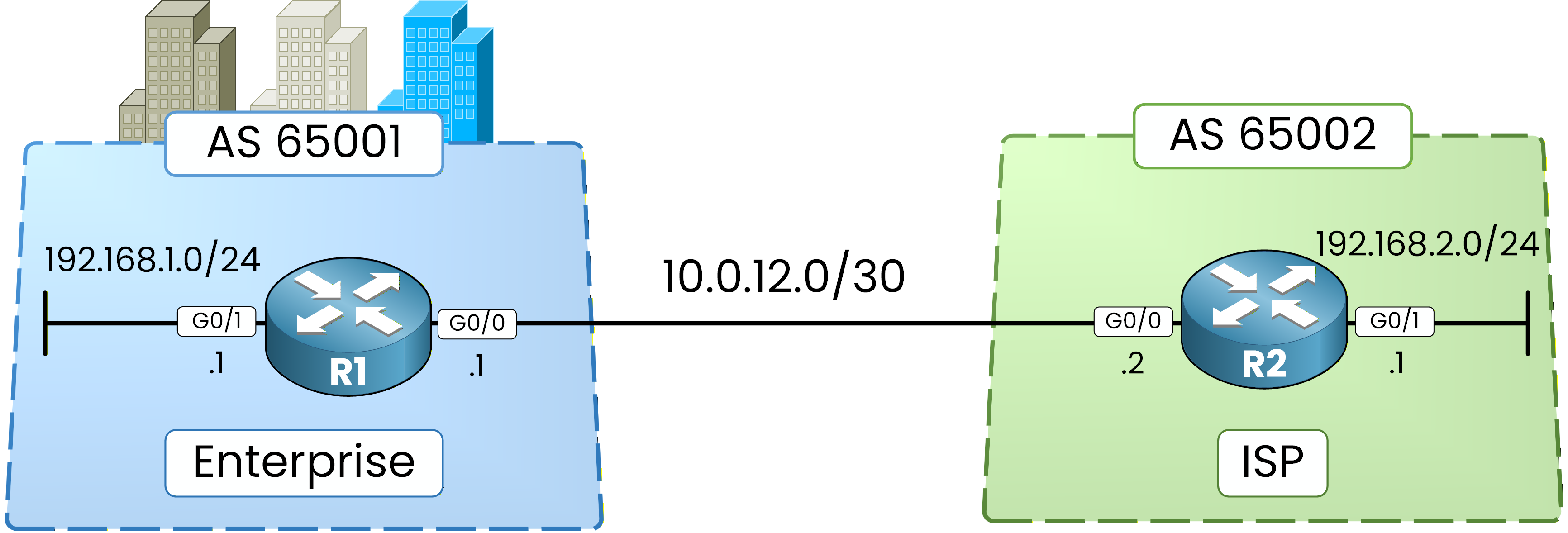
Figure 1 - Basic BGP Configuration Topology
In this topology:
R1 represents the Enterprise (AS 65001)
R2 represents the ISP (AS 65002)
The objective of this lab is simple:
Establish an eBGP session
Advertise local networks
Verify route exchange
Confirm connectivity
Let’s begin.
Step 1 – Interface Configuration
Before BGP can operate, the routers must be able to reach each other at Layer 3.
Start with R1:R1# conf t Enter configuration commands, one per line. End with CNTL/Z. R1(config)# int g0/0 R1(config-if)# ip address 10.0.12.1 255.255.255.252 R1(config-if)# no shut R1(config-if)# exit R1(config)# int g0/1 R1(config-if)# ip address 192.168.1.1 255.255.255.0 R1(config-if)# no shut R1(config-if)# exitHere you are doing two things:
Configuring the link toward the ISP (g0/0)
Configuring the Enterprise LAN (g0/1)
Now configure R2:
R2# conf t
Enter configuration commands, one per line.  End with CNTL/Z.
R2(config)# int g0/0
R2(config-if)# ip address 10.0.12.2 255.255.255.252
R2(config-if)# no shut
R2(config-if)# exit


R2(config)# int g0/1
R2(config-if)# ip address 192.168.2.1 255.255.255.0
R2(config-if)# no shut
R2(config-if)# exit
At this point:
Both routers have IP connectivity on the point-to-point link.
Each router has a local LAN network configured.
Now you are ready to activate BGP.
Step 2 – Configure eBGP Neighbors
You will now initialize BGP and define the neighbor relationship.
Start with R1:
R1(config)# router bgp 65001
R1(config-router)# neighbor 10.0.12.2 remote-as 65002
R1(config-router)# end
Here:
You declare that R1 belongs to AS 65001.
You define 10.0.12.2 as a neighbor in AS 65002.
Now configure R2:
R2(config)# router bgp 65002
R2(config-router)# neighbor 10.0.12.1 remote-as 65001
%BGP-5-ADJCHANGE: neighbor 10.0.12.1 Up
R2(config-router)# end
The message
%BGP-5-ADJCHANGE: neighbor 10.0.12.1 Upindicates that the BGP session has been successfully established.The two Autonomous Systems are now connected.
However, no routes have been exchanged yet.Step 3 – Verify BGP Session
Now verify the BGP session status.
At this stage, you have configured the neighbor relationship on both routers.
You must confirm that the session is properly established.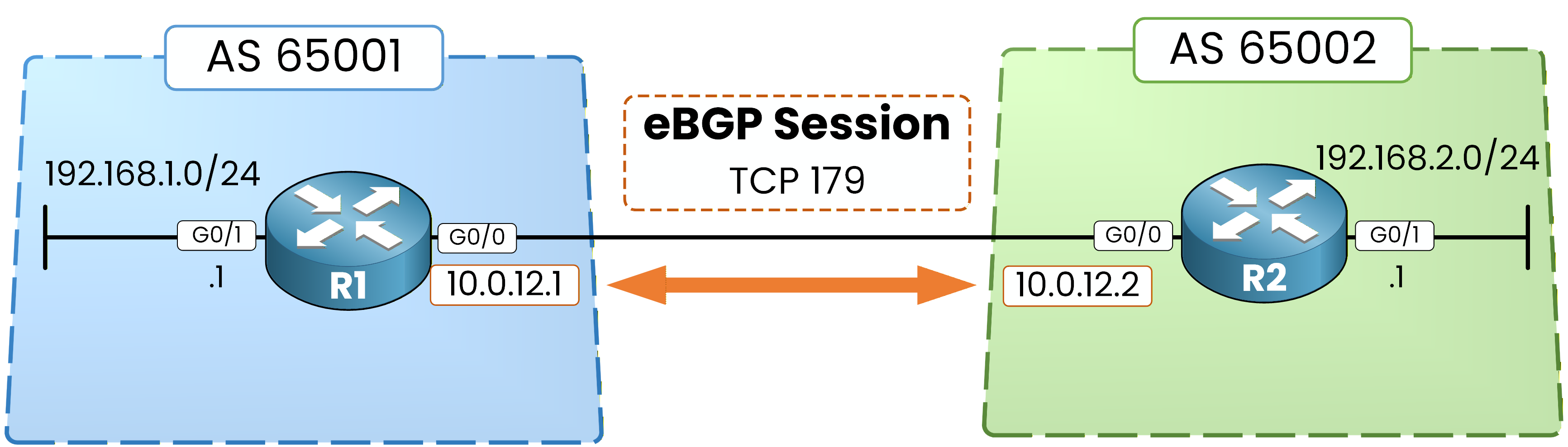
Figure 2 – eBGP Session over TCP 179
BGP sessions are always established over TCP using port 179.
Now check R1:R1# show bgp ipv4 unicast summary BGP router identifier 192.168.1.1, local AS number 65001 BGP table version is 1, main routing table version 1 Neighbor V AS MsgRcvd MsgSent TblVer InQ OutQ Up/Down State/PfxRcd 10.0.12.2 4 65002 29 29 1 0 0 00:00:30 0In this output, verify the following:
The Neighbor is 10.0.12.2 → this is R2.
The AS column shows 65002 → this confirms the remote Autonomous System.
The session shows counters increasing (MsgRcvd / MsgSent).
This confirms that R1 correctly sees its BGP neighbor and knows its remote AS.
Now check R2:
R2# show bgp ipv4 unicast summary
BGP router identifier 192.168.2.1, local AS number 65002
BGP table version is 1, main routing table version 1

Neighbor        V           AS MsgRcvd MsgSent   TblVer  InQ OutQ Up/Down  State/PfxRcd
10.0.12.1       4        65001      30      30        1    0    0 00:00:40        0
Again, confirm:
The Neighbor is 10.0.12.1 → this is R1.
The AS column shows 65001 → correct remote AS.
Message counters are active.
Finally, look at the
State/PfxRcdcolumn.
You see the value 0.This means:
The BGP session is Established (because it shows a number).
No prefixes have been received yet.
This is expected, since you have not advertised any networks at this point.
Answer the question below
Over which transport protocol does BGP establish its sessions?
The session is up but useless: neither router advertises anything yet.
In this section, you will check the empty BGP table, then feed it.Step 4 – Verify Initial BGP Table
Now check the BGP table itself.
On R1:R1# show bgp ipv4 unicast R1#The table is empty.
Now check on R2:R2# show bgp ipv4 unicast R2#The table is also empty.
This confirms an important concept:
An established BGP session does not automatically mean routes exist.Routes must be explicitly advertised.
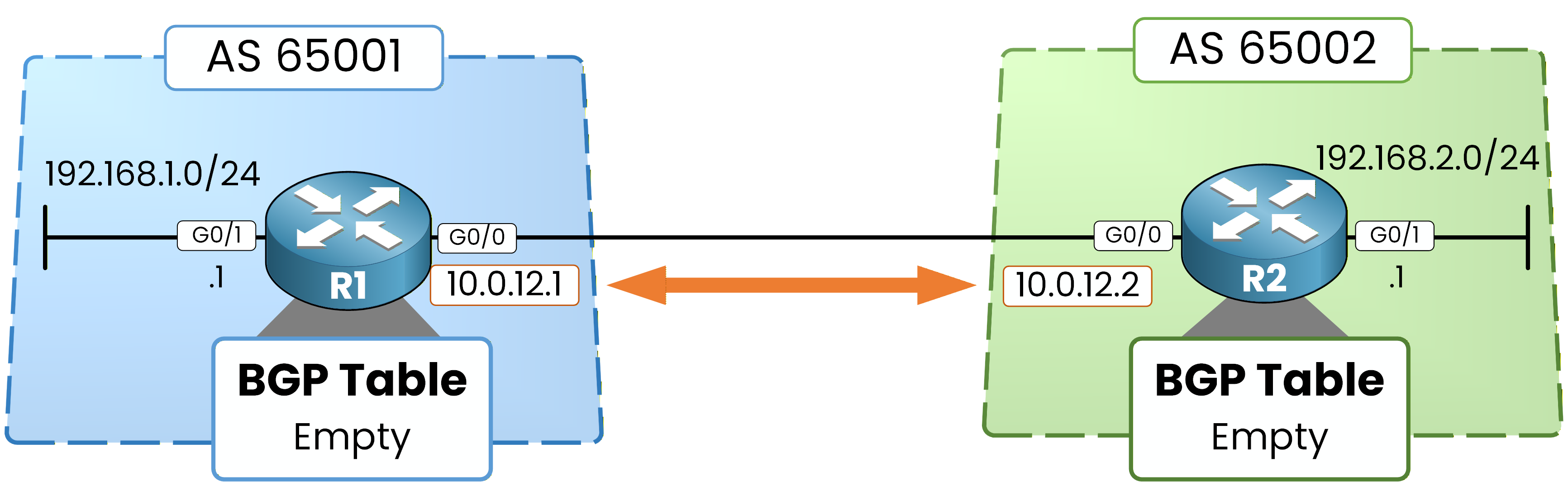
Figure 3 – Initial empty BGP tables
Both routers have:
An established BGP session
An empty BGP table
You are now ready to advertise networks.
Step 5 – Advertise Local Networks
Now you will inject each router’s LAN network into BGP.
Start with R1:
R1# conf t
Enter configuration commands, one per line.  End with CNTL/Z.
R1(config)# router bgp 65001
R1(config-router)# network 192.168.1.0 mask 255.255.255.0
R1(config-router)# end
Here, you are telling BGP:
"Advertise the 192.168.1.0/24 network into BGP."
Now configure R2:
R2# conf t
Enter configuration commands, one per line.  End with CNTL/Z.
R2(config)# router bgp 65002
R2(config-router)# network 192.168.2.0 mask 255.255.255.0
R2(config-router)# end
Now R2 advertises 192.168.2.0/24.
At this point:
Each router announces its local LAN.
Route exchange can now begin.
In the next step, you will verify that these prefixes appear in the BGP table.
Answer the question below
Which command advertises a prefix into BGP?
Advertising is only half the job.
You now confirm that the prefixes crossed the link and made it into each router's tables.Step 6 – Verify Route Exchange
Now that both routers are advertising their local networks, you must verify that the routes are being exchanged correctly.
You will inspect the BGP table again.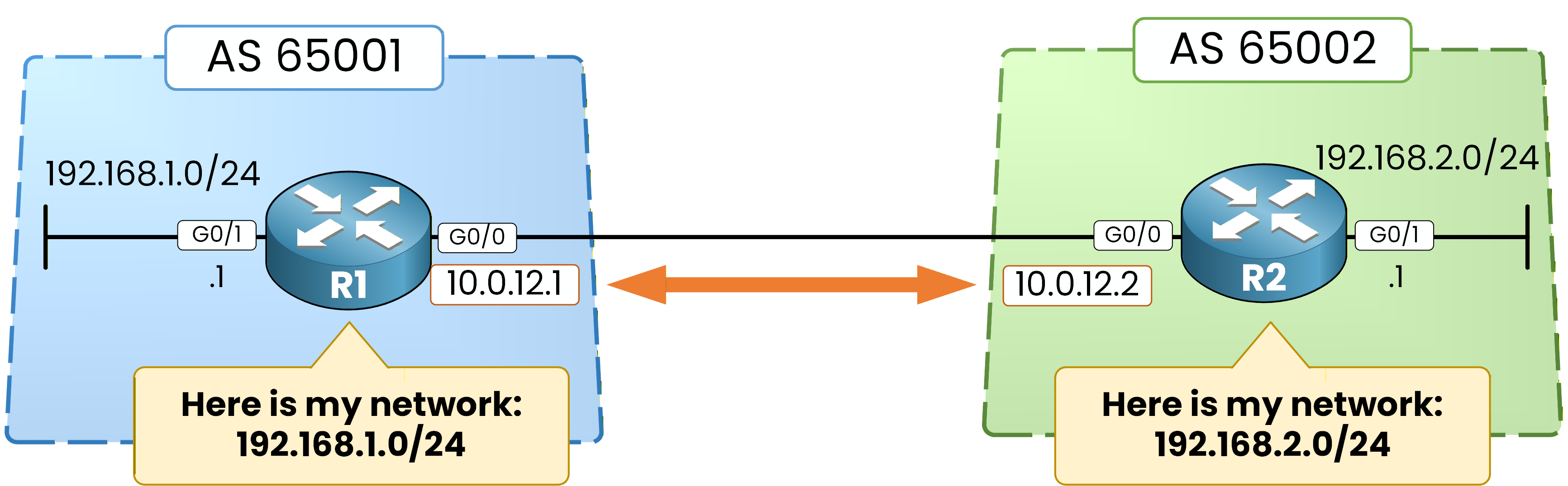
Figure 4 – Local network advertisement
This figure represents the moment where each router advertises its LAN prefix into BGP.
Now check R1:
R1# show bgp ipv4 unicast
BGP table version is 3, local router ID is 192.168.1.1
Status codes: s suppressed, d damped, h history, * valid, > best, i - internal,
              r RIB-failure, S Stale, m multipath, b backup-path, f RT-Filter,
              x best-external, a additional-path, c RIB-compressed,
              t secondary path,
Origin codes: i - IGP, e - EGP, ? - incomplete
RPKI validation codes: V valid, I invalid, N Not found

     Network          Next Hop            Metric LocPrf Weight Path
 *>   192.168.1.0      0.0.0.0                  0         32768 i
 *>   192.168.2.0      10.0.12.2                0             0 65002 i
You can observe two important entries:
192.168.1.0 → This is the local network.
192.168.2.0 → This was learned from AS 65002.
Look carefully at the columns:
Next Hopshows where the route is reachable.Pathshows the originating AS.*>means the route is valid and selected as the best path.
Now verify the same behavior on R2:
R2# show bgp ipv4 unicast
BGP table version is 3, local router ID is 192.168.2.1
Status codes: s suppressed, d damped, h history, * valid, > best, i - internal,
              r RIB-failure, S Stale, m multipath, b backup-path, f RT-Filter,
              x best-external, a additional-path, c RIB-compressed,
              t secondary path,
Origin codes: i - IGP, e - EGP, ? - incomplete
RPKI validation codes: V valid, I invalid, N Not found

     Network          Next Hop            Metric LocPrf Weight  Path
 *>   192.168.1.0      10.0.12.1                0             0 65001 i
 *>   192.168.2.0      0.0.0.0                  0         32768 i
Here you see the mirrored result:
R2 now knows about 192.168.1.0.
The AS path shows 65001.
The next hop is 10.0.12.1.
This confirms that route exchange between the two Autonomous Systems is functioning correctly.
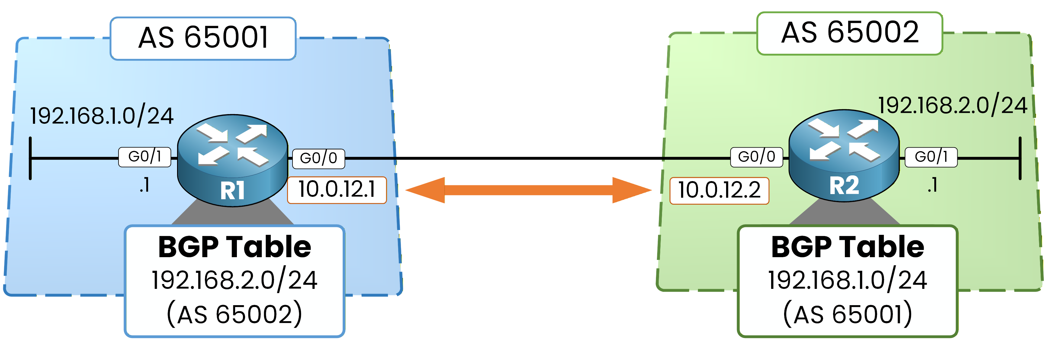
Figure 5 – eBGP route exchange
Both routers now advertise and learn each other’s LAN networks.
The BGP tables are populated.Step 7 – Verify Routing Table
Having routes in the BGP table does not automatically mean they are installed in the routing table.
Now you will verify that BGP has inserted the learned routes into the RIB.On R1:
R1# show ip route bgp
Codes: L - local, C - connected, S - static, R - RIP, M - mobile, B - BGP
       D - EIGRP, EX - EIGRP external, O - OSPF, IA - OSPF inter area
       N1 - OSPF NSSA external type 1, N2 - OSPF NSSA external type 2
       E1 - OSPF external type 1, E2 - OSPF external type 2
       i - IS-IS, su - IS-IS summary, L1 - IS-IS level-1, L2 - IS-IS level-2
       ia - IS-IS inter area, * - candidate default, U - per-user static route
       o - ODR, P - periodic downloaded static route, H - NHRP, l - LISP
       a - application route
       + - replicated route, % - next hop override, p - overrides from PfR

Gateway of last resort is not set

B     192.168.2.0/24 [20/0] via 10.0.12.2, 00:02:04
This line confirms:
The route is marked with
B(learned via BGP).The next hop is 10.0.12.2.
The Administrative Distance is 20 (default for eBGP).
Now check R2:
R2# show ip route bgp
Codes: L - local, C - connected, S - static, R - RIP, M - mobile, B - BGP
       D - EIGRP, EX - EIGRP external, O - OSPF, IA - OSPF inter area
       N1 - OSPF NSSA external type 1, N2 - OSPF NSSA external type 2
       E1 - OSPF external type 1, E2 - OSPF external type 2
       i - IS-IS, su - IS-IS summary, L1 - IS-IS level-1, L2 - IS-IS level-2
       ia - IS-IS inter area, * - candidate default, U - per-user static route
       o - ODR, P - periodic downloaded static route, H - NHRP, l - LISP
       a - application route
       + - replicated route, % - next hop override, p - overrides from PfR

Gateway of last resort is not set

B     192.168.1.0/24 [20/0] via 10.0.12.1, 00:03:02
You can confirm:
R2 has installed the route to 192.168.1.0.
The next hop is R1.
The route is active in the routing table.
At this point:
The BGP session is established.
Routes are exchanged.
Routes are installed in the routing table.
Answer the question below
What is the Administrative Distance of an eBGP route?
Tables are populated.
The final proof is traffic actually flowing between the two LANs.Step 8 – Ping from the Enterprise
Now, you will verify end-to-end connectivity.
This confirms that traffic can actually flow between the two Autonomous Systems.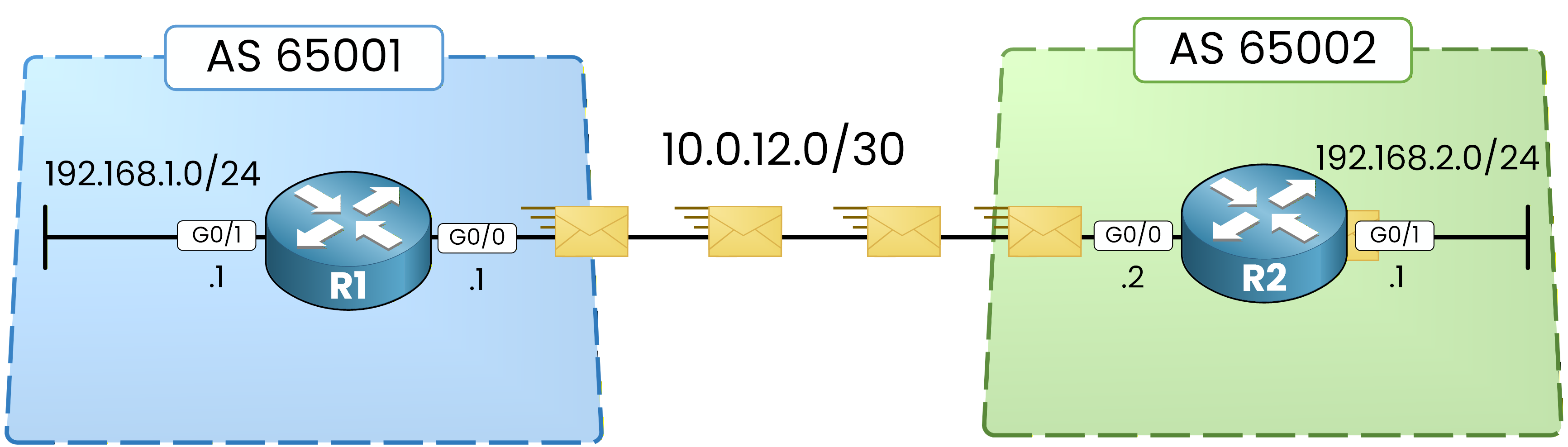
Figure 6 – Ping from R1 to 192.168.2.1
From R1, send an ICMP echo to the LAN interface of R2.
R1# ping 192.168.2.1
Type escape sequence to abort.
Sending 5, 100-byte ICMP Echos to 192.168.2.1, timeout is 2 seconds:
!!!!!
Success rate is 100 percent (5/5), round-trip min/avg/max = 1/2/4 ms
The
!!!!!output indicates that all packets were successfully delivered and replies were received.Step 9 – Ping from the ISP
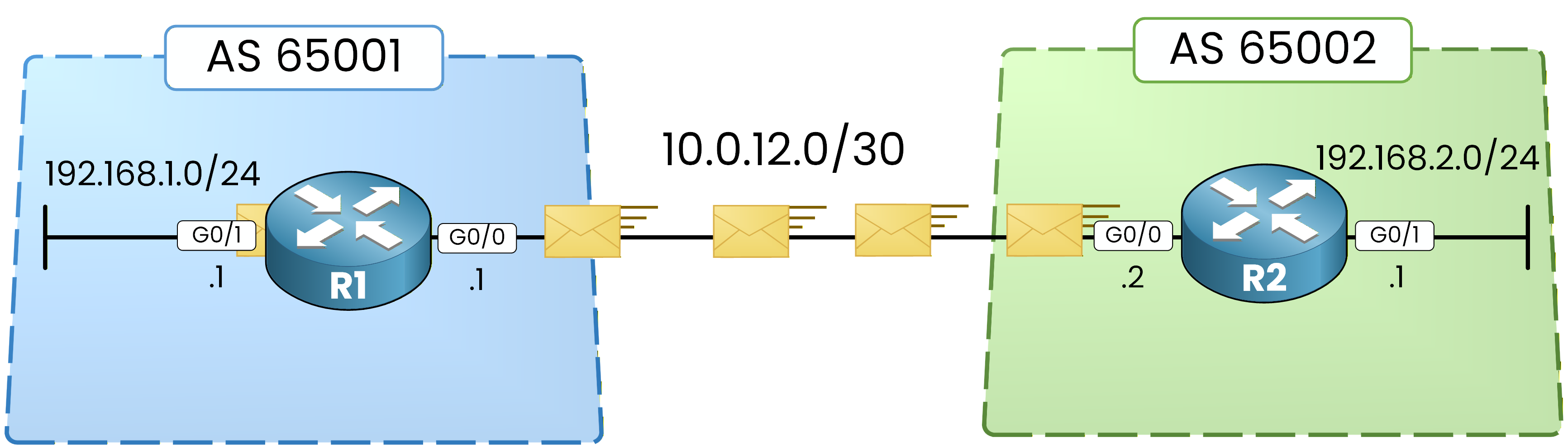
Figure 7 - Ping from R2 to 192.168.1.1
Now test connectivity in the opposite direction.
R2# ping 192.168.1.1
Type escape sequence to abort.
Sending 5, 100-byte ICMP Echos to 192.168.1.1, timeout is 2 seconds:
!!!!!
Success rate is 100 percent (5/5), round-trip min/avg/max = 1/2/4 ms
Again, all packets are successfully received.
This confirms bidirectional communication between:AS 65001
AS 65002
At this point, your eBGP configuration is fully operational.
This is the traditional BGP configuration model. In the next lesson, you will rebuild this exact session using the modern address-family model.
Answer the question below
Does an established BGP session automatically mean routes exist?