In this lesson, you are going to configure R3 as the Designated Router (DR) and R4 as the Backup Designated Router (BDR) on a shared Ethernet segment.
Then you will break the DR on purpose and watch who takes its place.The Four Routers
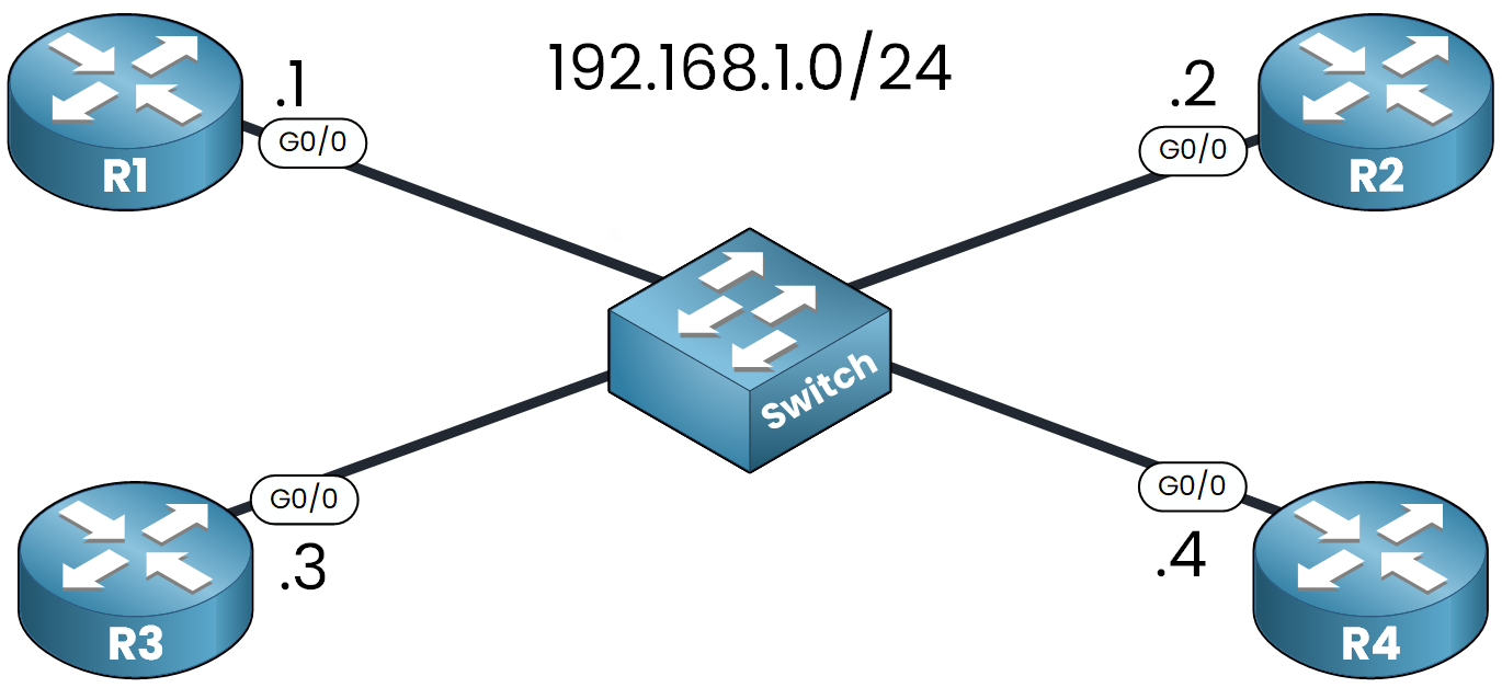
Figure 1 – Topology used for the configuration of DR and BDR
Our topology includes four routers:
R1: 192.168.1.1
R2: 192.168.1.2
R3: 192.168.1.3
R4: 192.168.1.4
All routers are connected to the 192.168.1.0/24 subnet through their GigabitEthernet0/0 interface.
No router-id is configured, so each router uses its G0/0 address as Router ID.OSPF Configuration on All Routers
On each router, enable OSPF and advertise the shared network. Start with R1:
R1# conf t
Enter configuration commands, one per line.  End with CNTL/Z.
R1(config)# router ospf 1
R1(config-router)# network 192.168.1.0 0.0.0.255 area 0
R1(config-router)# end
Repeat the exact same three commands on R2, R3 and R4.
The network statement includes G0/0 in OSPF and immediately triggers the DR/BDR election.Answer the question below
Which subnet do all four routers share on G0/0?
At this stage, you have not configured any OSPF priority.
All routers are using the default priority of 1.Reading the Neighbor Table
On R1, check which roles the election handed out:
R1# show ip ospf neighbor

Neighbor ID      Pri  State          Dead Time   Address      Interface
192.168.1.3       1   FULL/BDR       00:00:23    192.168.1.3  GigabitEthernet0/0
192.168.1.4       1   FULL/DR        00:00:23    192.168.1.4  GigabitEthernet0/0
192.168.1.2       1   2WAY/DROTHER   00:00:23    192.168.1.2  GigabitEthernet0/0
Neighbor ID 192.168.1.4, which is R4, is seen as the DR. Neighbor ID 192.168.1.3, which is R3, is seen as the BDR.
R2 stays in 2WAY with R1, because both are DROTHERs.Why R4 Won
When priorities are equal, OSPF uses the highest Router ID to elect the DR.
The router with the second-highest Router ID becomes the BDR.R4 has the highest Router ID, 192.168.1.4, and is elected DR
R3 has the next highest Router ID, 192.168.1.3, and is elected BDR
This is not the result you want. R3 should be the DR.
Answer the question below
When priorities are equal, which value decides the DR?
To make R3 the new DR, you raise its OSPF priority above the others.
Then you will discover that this alone is not enough.Raising the Priority
The priority is an interface setting. On R3:
R3# conf t
Enter configuration commands, one per line.  End with CNTL/Z.
R3(config)# interface g0/0
R3(config-if)# ip ospf priority 100
R3(config-if)# end
Changing the priority alone does not affect the current election. OSPF elections are non-preemptive: once the DR and BDR are elected, they keep their role even if a router with a higher priority appears.
To trigger a new election, you need to reset the OSPF process.
Restarting OSPF
Clear the OSPF process on R3:
R3# clear ip ospf process
Reset ALL OSPF processes? [no]: yes
%OSPF-5-ADJCHG: Process 1, Nbr 192.168.1.4 on GigabitEthernet0/0 from FULL to DOWN, Neighbor Down: Adjacency forced to reset
%OSPF-5-ADJCHG: Process 1, Nbr 192.168.1.1 on GigabitEthernet0/0 from FULL to DOWN, Neighbor Down: Adjacency forced to reset
This command resets all adjacencies on R3 and forces a new DR/BDR election on the segment.
Verifying the New Election
After OSPF reconverges, check again from R1:
R1# show ip ospf neighbor

Neighbor ID   Pri    State         Dead Time  Address      Interface
192.168.1.4    1     FULL/BDR      00:00:24   192.168.1.4  GigabitEthernet0/0
192.168.1.3    100   FULL/DR       00:00:24   192.168.1.3  GigabitEthernet0/0
192.168.1.2    1     2WAY/DROTHER  00:00:24   192.168.1.2  GigabitEthernet0/0
R3 is now the DR thanks to its priority of 100, and R4 is the BDR.
You can confirm the role directly on R3:R3# show ip ospf interface g0/0 GigabitEthernet0/0 is up, line protocol is up Internet address is 192.168.1.3/24, Area 0 Process ID 1, Router ID 192.168.1.3, Network Type BROADCAST, Cost: 1 Transmit Delay is 1 sec, State DR, Priority 100 Designated Router (ID) 192.168.1.3, Interface address 192.168.1.3 Backup Designated Router (ID) 192.168.1.4, Interface address 192.168.1.4 Timer intervals configured, Hello 10, Dead 40, Wait 40, Retransmit 5 Hello due in 00:00:00 Index 1/1, flood queue length 0 Next 0x0(0)/0x0(0) Last flood scan length is 1, maximum is 1 Last flood scan time is 0 msec, maximum is 0 msec Neighbor Count is 3, Adjacent neighbor count is 3 Adjacent with neighbor 192.168.1.4 (Backup Designated Router) Adjacent with neighbor 192.168.1.2 Adjacent with neighbor 192.168.1.1 Suppress hello for 0 neighbor(s)As the DR, R3 is adjacent with all three other routers.
A DROTHER would only list the DR and the BDR here.Answer the question below
Which command triggers a new DR/BDR election?
When the DR fails, the current BDR automatically becomes the new DR.
Then a new BDR is elected among the remaining DROTHERs.You are going to see it happen.
Before the Failure
This is the state of the segment right now:
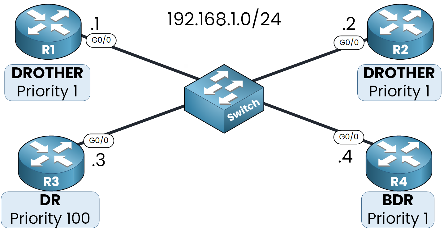
Figure 2 – R3 is DR, R4 is BDR, R1 and R2 are DROTHERs
Now imagine R3 goes down. The expected result is below:
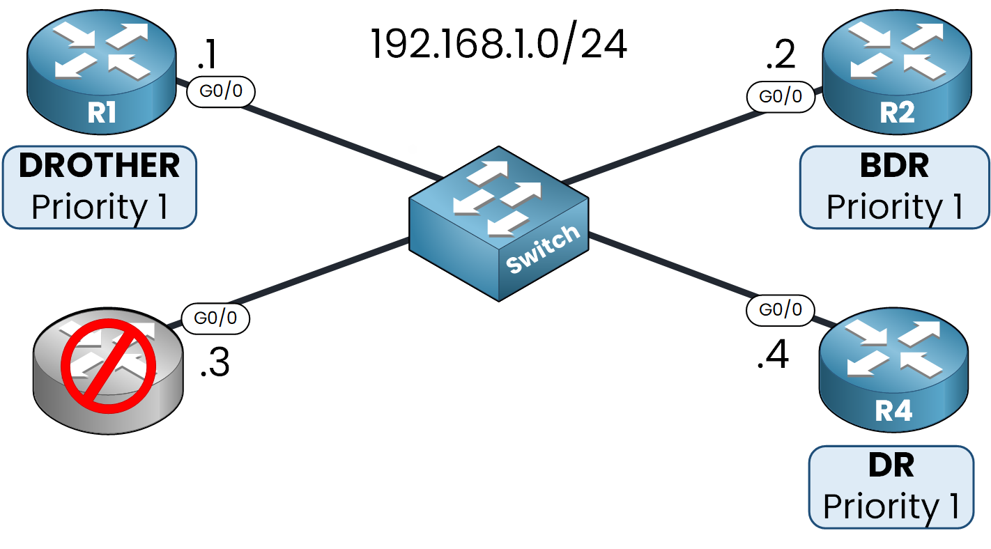
Figure 3 – R3 fails, R4 becomes DR and a new BDR is elected
Simulating the DR Failure
To simulate the failure, shut down the OSPF interface of R3:
R3# conf t
Enter configuration commands, one per line.  End with CNTL/Z.
R3(config)# interface g0/0
R3(config-if)# shutdown

%LINK-5-CHANGED: Interface GigabitEthernet0/0, changed state to administratively down
%LINEPROTO-5-UPDOWN: Line protocol on Interface GigabitEthernet0/0, changed state to down
Once the interface is down, R3 stops sending Hello packets. OSPF does not remove the adjacency right away: the other routers wait for the dead timer, 40 seconds by default.
After that, R4 is promoted to DR and one of the DROTHERs is elected as the new BDR.Verifying from R1
Wait for the dead timer, then check the neighbor table on R1:
R1# show ip ospf neighbor

Neighbor ID     Pri   State       Dead Time   Address         Interface
192.168.1.4       1   FULL/DR     00:00:35    192.168.1.4     GigabitEthernet0/0
192.168.1.2       1   FULL/BDR    00:00:35    192.168.1.2     GigabitEthernet0/0
R4 is now the DR
R2 has become the new BDR, and R1 now reaches FULL with it
R3 no longer appears because its adjacency was removed after the dead timer expired
Notice that R4 was not re-elected on priority or Router ID. It was promoted because it was the BDR. That is the whole point of keeping a backup ready.
Now do it again in the next lab, without the guide.
Answer the question below
Which router takes over when the DR fails?