In this lab, you'll learn how to configure Network Time Protocol (NTP) so your devices can keep accurate and synchronized time. Clock synchronization is essential in networking because logs, monitoring tools, and security features depend on precise timestamps.
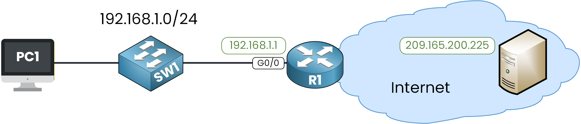
Figure 1 - NTP Lab Configuration Topology
This lab will guide you through configuring and verifying NTP.
You’ll see how a router learns time from an external server and then provides synchronized time to a switch.Lab Overview
In this lab, you will complete the following tasks:
Step 1 – Verify Initial Clock and Connectivity
Step 2 – Configure Timezone and Manual Clock
Step 3 – Configure SW1 as an NTP Client
Step 4 – Configure R1 to Sync with an External NTP Server
Step 5 – Verify NTP Client Synchronization on SW1
Step 6 – Convert R1 into an NTP Master
Let’s Get Started
Try to complete the tasks on your own. Each step is designed to guide you through the process, and if you get stuck, the explanations below will help you understand exactly what to do.
Let’s go!
Answer the question below
Click 'Complete' to continue
First, let’s check whether R1 can reach the external NTP server on the internet.
We can use the ping command:R1# ping 209.165.200.225 Type escape sequence to abort. Sending 5, 100-byte ICMP Echos to 209.165.200.225, timeout is 2 seconds: !!!!! Success rate is 100 percent (5/5), round-trip min/avg/max = 0/0/1 msGreat, communication is working.
This confirms that R1 has IP reachability to the public NTP server, which is required before it can synchronize its clock using NTP.Check the Initial NTP State
Now let’s look at the NTP status on R1:
R1# show ntp status
%NTP is not enabled.
NTP is disabled by default on Cisco devices.
It only starts running after you configure an NTP server or enable NTP master, so this output is completely normal at this stage.
Let’s check SW1 as well:SW1# show ntp status %NTP is not enabled.This result is expected since we haven’t configured NTP yet.
Check the Device Clocks
Now let’s take a look at the device clocks. Here is the output on SW1:
SW1# show clock detail
*0:1:54.990 UTC Mon Mar 1 1993
Time source is hardware calendar
And on R1:
R1# show clock detail
*0:1:48.709 UTC Mon Mar 1 1993
Time source is hardware calendar
You can see that:
The date is incorrect (1993), which is normal when no valid time source is available.
The line Time source is hardware calendar indicates that the device is simply using its internal clock.
In the next step, we’ll set the timezone and manually adjust the clock so both devices start from a consistent time before configuring NTP.
Let’s continue!
Answer the question below
What is the current time source?
Before using NTP, let’s see how to configure the local time manually on a Cisco device.
This helps you understand how the clock works before we automate everything with NTP.Set the Timezone
R1# conf t
Enter configuration commands, one per line.  End with CNTL/Z.
R1(config)# clock timezone UTC 0
R1(config)# exit
We set the router to UTC with an offset of 0.
Set the Local Clock
Now let’s manually configure the date and time on R1:
R1# clock set 10:52:00 13 December 2025Verify:
R1# show clock detail
10:52:3.63 UTC Sat Dec 13 2025
Time source is user configuration
The clock is now correctly set, and the device shows Time source is user configuration, meaning the time was set manually.
Now apply the same configuration on SW1:
SW1# conf t
Enter configuration commands, one per line.  End with CNTL/Z.
SW1(config)# clock timezone UTC 0
SW1(config)# exit
SW1# clock set 10:52:10 13 December 2025
And verify:
SW1# show clock detail
10:52:2.131 UTC Sat Dec 13 2025
Time source is user configuration
Both devices now have a consistent manual clock.
Manually configuring time is useful for labs, but in real networks clocks drift over time.
This is exactly why NTP is needed.Let’s continue and start configuring NTP.
Answer the question below
What is the time source now?
Here is the NTP hierarchy we will configure in this lab:
SW1 gets its time from R1, and R1 gets its time from the public NTP server.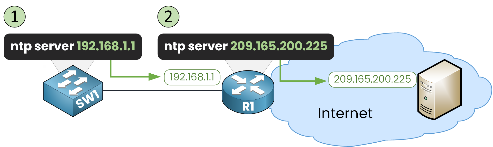
Figure 2 - NTP Configuration Steps
Configure SW1 to Use R1 as its NTP Server
SW1# conf t
Enter configuration commands, one per line.  End with CNTL/Z.
SW1(config)# ntp server 192.168.1.1
SW1(config)# end
Check the Initial NTP State on SW1
Once the configuration is applied, we can check the NTP status:
SW1# show ntp status
Clock is unsynchronized, stratum 16, no reference clock
nominal freq is 250.0000 Hz, actual freq is 249.9990 Hz, precision is 2**24
reference time is 00000000.00000000 (00:00:00.000 UTC Mon Jan 1 1990)
clock offset is 0.00 msec, root delay is 0.00  msec
root dispersion is 0.00 msec, peer dispersion is 0.00 msec.
loopfilter state is 'FSET' (Drift set from file), drift is - 0.000001193 s/s system poll interval is 4, never updated.
The clock is still unsynchronized, and the device remains stratum 16.
This is normal because R1 is not synchronized yet, so SW1 has no valid time source.Check the NTP Associations
SW1# show ntp associations

address         ref clock       st   when     poll    reach  delay          offset            disp
 ~192.168.1.1   .INIT.          16   -        64      0      0.00           0.00              0.12
 * sys.peer, # selected, + candidate, - outlyer, x falseticker, ~ configured
Here’s what this tells us:
The ~ symbol indicates that 192.168.1.1 is a configured NTP server.
The .INIT. state means SW1 has not yet received any valid NTP packets from R1.
SW1 stays at stratum 16 because it is still unsynchronized.
Everything here is expected at this point in the lab.
Next, we need to configure R1 so it can synchronize with the external NTP server.Let’s continue.
Answer the question below
What is SW1’s stratum now?
Now that SW1 is ready to learn its time from R1, we first need to configure R1 to synchronize with an external NTP server on the internet. Once R1 has accurate time, it will automatically act as an NTP server for the rest of the network.
Configure the External NTP Server on R1
R1# conf t
Enter configuration commands, one per line.  End with CNTL/Z.
R1(config)# ntp server 209.165.200.225
R1(config)# end
Check the Initial NTP Status
Right after applying the configuration, R1 is still unsynchronized:
R1# show ntp status
Clock is unsynchronized, stratum 16, no reference clock
nominal freq is 250.0000 Hz, actual freq is 249.9990 Hz, precision is 2**24
reference time is 00000000.00000000 (00:00:00.000 UTC Mon Jan 1 1990)
clock offset is 0.00 msec, root delay is 0.00  msec
root dispersion is 0.00 msec, peer dispersion is 0.00 msec.
loopfilter state is 'FSET' (Drift set from file), drift is - 0.000001193 s/s system poll interval is 4, never updated.
This is completely normal.
NTP needs several packet exchanges before it can trust an external source. If you check again after a few seconds, the output may still be the same.Check the NTP status again:
R1# show ntp status
Clock is synchronized, stratum 2, reference is 209.165.200.225
nominal freq is 250.0000 Hz, actual freq is 249.9990 Hz, precision is 2**24
reference time is ECB3D89F.000001C5 (1:42:55.453 UTC Tue Dec 13 2025)
clock offset is 0.00 msec, root delay is 0.00  msec
root dispersion is 27.21 msec, peer dispersion is 0.24 msec.
loopfilter state is 'CTRL' (Normal Controlled Loop), drift is - 0.000001193 s/s system poll interval is 6, last update was 2 sec ago.
As you can see, R1 is now synchronized with the external NTP server 209.165.200.225.
It has become a stratum 2 device. Remember that the public NTP server is stratum 1, so this matches the stratum hierarchy we learned earlier.Let’s also verify the local clock:
R1# show clock detail
1:49:54.259 UTC Tue Dec 13 2025
Time source is NTP
Next, verify the NTP associations:
R1# show ntp associations

address            ref clock       st   when     poll    reach  delay          offset            disp
*~209.165.200.225  127.127.1.1     1    32       64      373    2.00           0.00              0.48
 * sys.peer, # selected, + candidate, - outlyer, x falseticker, ~ configured
R1 has correctly selected 209.165.200.225 as its NTP peer and is now fully synchronized.
It is ready to provide accurate time to SW1.Answer the question below
What is the reference clock used by R1?
At this stage, SW1 is already configured to use R1 as its NTP server.
Now that R1 is synchronized with the external NTP source, SW1 should also be able to synchronize through R1.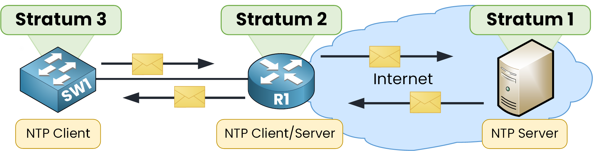
Figure 3 - NTP Architecture
Check that SW1 is now synchronized
Start by checking the clock:
SW1# show clock detail
1:51:16.701 UTC Tue Dec 13 2025
Time source is NTP
Perfect, the time source is now NTP, which confirms that SW1 successfully received time information from R1.
Check the NTP associations
SW1# show ntp associations

address         ref clock       st   when     poll    reach  delay          offset            disp
*~192.168.1.1   209.165.200.225 2    19       64      377    0.00           0.00              0.48
 * sys.peer, # selected, + candidate, - outlyer, x falseticker, ~ configured
Here’s what this tells us:
• SW1 is synchronized with 192.168.1.1 (R1).
• R1 itself is synchronized with 209.165.200.225, shown under the reference clock column.
• R1 is stratum 2, so SW1 becomes stratum 3.Finally, let’s check the NTP status:
SW1# show ntp status
Clock is synchronized, stratum 3, reference is 192.168.1.1
nominal freq is 250.0000 Hz, actual freq is 249.9990 Hz, precision is 2**24
reference time is ECB3DA84.00000091 (1:51:0.145 UTC Tue Dec 13 2025)
clock offset is 0.00 msec, root delay is 0.00  msec
root dispersion is 44.39 msec, peer dispersion is 0.48 msec.
loopfilter state is 'CTRL' (Normal Controlled Loop), drift is - 0.000001193 s/s system poll interval is 6, last update was 22 sec ago.
SW1 is fully synchronized, with R1 as its NTP reference.
Your NTP hierarchy is now functioning exactly as expected!Answer the question below
What is SW1’s stratum now?
Now that R1 is synchronized with the external NTP server, we will change its role.
In this final step, R1 will stop using the public NTP source and instead act as the internal NTP master for the entire network.
This ensures that devices can still maintain a consistent time even if the external NTP source becomes unreachable.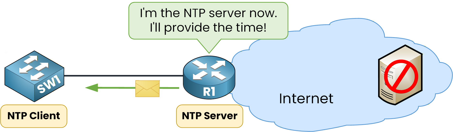
Figure 4 - NTP Master Concept
Configure R1 as the NTP Master
To switch R1 to master mode, remove the external NTP server configuration and enable
ntp master:R1# conf t Enter configuration commands, one per line. End with CNTL/Z. R1(config)# no ntp server 209.165.200.225 R1(config)# ntp master R1(config)# endBy default, the
ntp mastercommand sets the router to stratum 8.Verify R1 as the New Time Source
After a short delay, check R1’s NTP status:
R1# show ntp status
Clock is synchronized, stratum 8, reference is 127.127.1.1
nominal freq is 250.0000 Hz, actual freq is 249.9990 Hz, precision is 2**24
reference time is AF1ED22A.000001A1 (0:11:22.417 UTC Mon Mar 1 1993)
clock offset is 0.00 msec, root delay is 0.00  msec
root dispersion is 0.00 msec, peer dispersion is 0.48 msec.
loopfilter state is 'CTRL' (Normal Controlled Loop), drift is - 0.000001193 s/s system poll interval is 6, last update was 11 sec ago.
You’ll notice two important points:
• The router is synchronized as stratum 8.
• The reference clock is 127.127.1.1, which represents the local clock (R1 now uses its own hardware clock as the source of truth).This is exactly what we expect from an NTP master.
Verify That SW1 Synchronizes to the New Master
Now let’s check SW1:
SW1# show ntp status
Clock is synchronized, stratum 9, reference is 192.168.1.1
nominal freq is 250.0000 Hz, actual freq is 249.9990 Hz, precision is 2**24
reference time is AF1ED224.00000393 (0:11:16.915 UTC Mon Mar 1 1993)
clock offset is 0.00 msec, root delay is 0.00  msec
root dispersion is 10.87 msec, peer dispersion is 0.24 msec.
loopfilter state is 'CTRL' (Normal Controlled Loop), drift is - 0.000001193 s/s system poll interval is 5, last update was 4 sec ago.
SW1 has now become stratum 9, meaning it is learning time from R1 (stratum 8).
Everything is functioning correctly in the new hierarchy.Before we move to the lab summary, keep this in mind:
NTP is a slow protocol.
Answer the question below
What is R1’s stratum now?
Great job completing the NTP Configuration Lab!
In this lab, you learned how to give your network accurate and synchronized time, which is essential for logs, security, monitoring and troubleshooting. You configured devices step by step, verified synchronization and built a real NTP hierarchy between R1 and SW1.
Here are the key commands you should remember:
Set timezone
R1(config)# clock timezone UTC 0Set the clock manually
R1# clock set HH:MM:SS DAY MONTH YEARConfigure an NTP client
R1(config)# ntp server <ip-address>Configure an NTP master
R1(config)# ntp master [stratum]Verify NTP
R1# show ntp status
R1# show ntp associations
Thank you for completing this lab. You’re progressing really well.
Whenever you’re ready, continue with the next lesson and keep building your skills.Answer the question below
Click 'Complete' to continue