In this lab, you will learn how to configure 802.1Q trunking between two switches so VLANs can extend across multiple devices.
This is the topology we will use to practice the concept of 802.1Q Trunking.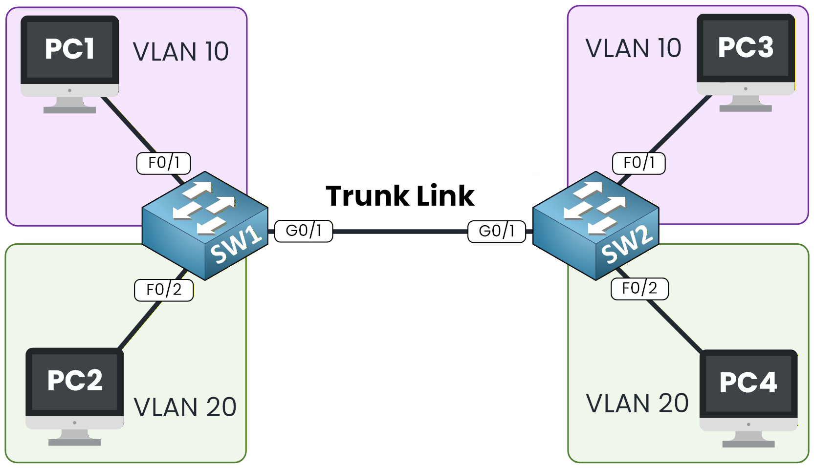
Figure 1 – 802.1Q Configuration Topology
This lab will guide you through the configuration, verification, and testing of 802.1Q trunks so you understand exactly how VLANs propagate between switches.
The switch connections are already in place, so you can focus entirely on the VLAN and trunk configuration.
Addressing used in this lab:
PC1 (VLAN 10) → 10.0.1.1 /24
PC3 (VLAN 10) → 10.0.1.3 /24
PC2 (VLAN 20) → 10.0.2.2 /24
PC4 (VLAN 20) → 10.0.2.4 /24Notice that PC1 and PC3 share the same subnet, and PC2 and PC4 share another one. Each VLAN stays inside a single subnet, so no router is needed in this lab. The trunk alone is enough to carry VLAN 10 and VLAN 20 traffic between the two switches. If you rebuild this topology in Packet Tracer, use exactly these addresses and masks, otherwise your pings will time out.
Lab Overview
Here’s the structure we will follow throughout this lab:
Step 1 – Configure VLANs and Access Ports on SW1
Step 2 – Configure VLANs and Access Ports on SW2
Step 3 – Configure 802.1Q Trunking
Step 4 – Verify Trunk BehaviorLet’s get started!
Answer the question below
Which two VLANs will you configure in this lab?
To begin, we need to create the two VLANs used in this topology: VLAN 10 and VLAN 20.
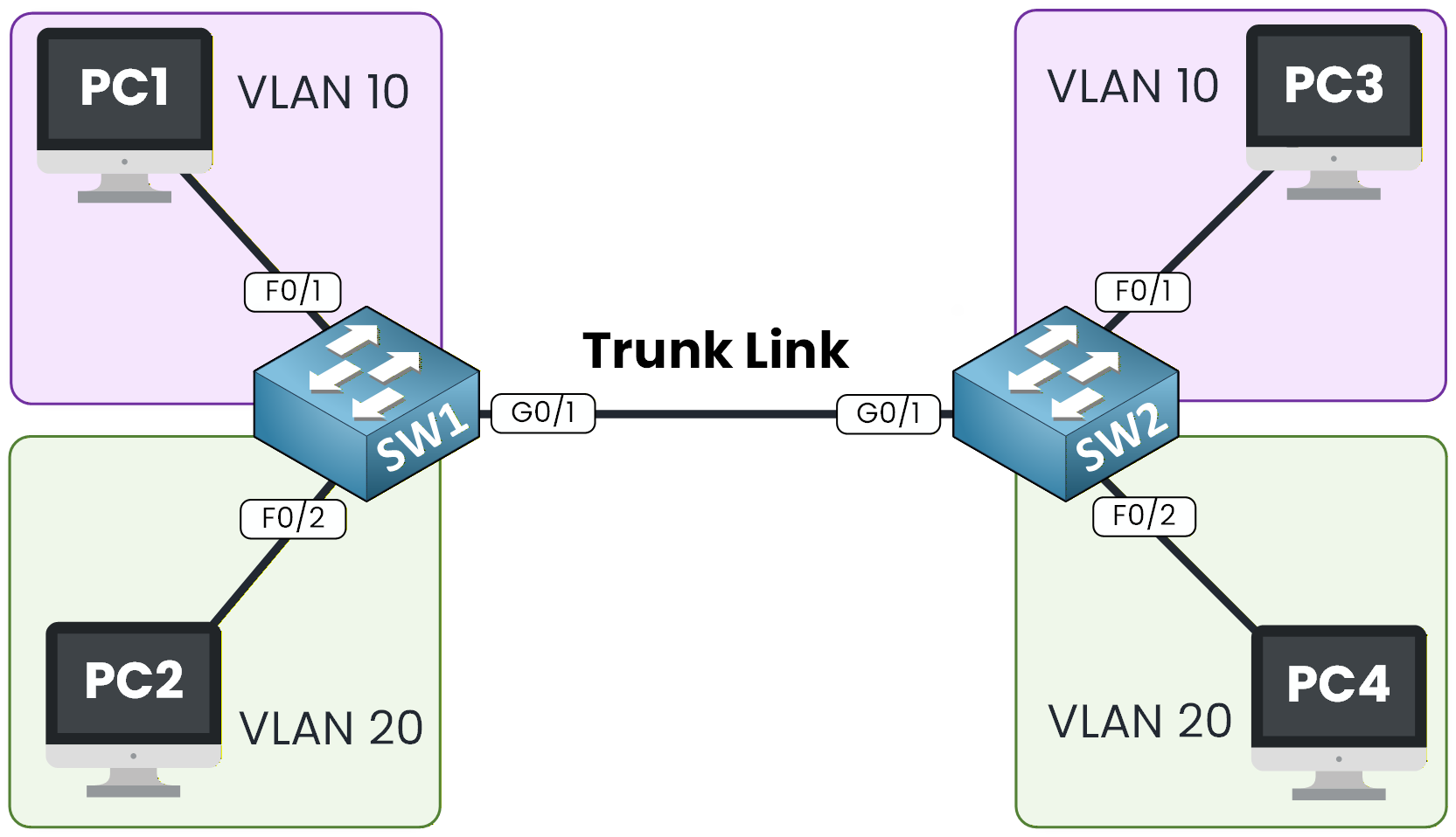
Figure 2 – 802.1Q Topology Example
Create VLAN 10 and VLAN 20
The process of creating a VLAN is simple.
You only need to enter the VLAN number, and you can optionally assign a name to make the configuration easier to read.SW1# conf t Enter configuration commands, one per line. End with CNTL/Z. SW1(config)# vlan 10 SW1(config-vlan)# name Sales SW1(config-vlan)# exit SW1(config)# vlan 20 SW1(config-vlan)# name Tech SW1(config-vlan)# endThen, after creating VLAN 10 and VLAN 20, we can verify that the VLANs are present.
On the switch, type the commandshow vlan briefSW1# show vlan brief VLAN Name Status Ports ---- -------------------------------- --------- ------------------------------- 1 default active Fa0/1, Fa0/2, Fa0/3, Fa0/4 Fa0/5, Fa0/6, Fa0/7, Fa0/8 Fa0/9, Fa0/10, Fa0/11, Fa0/12 Fa0/13, Fa0/14, Fa0/15, Fa0/16 Fa0/17, Fa0/18, Fa0/19, Fa0/20 Fa0/21, Fa0/22, Fa0/23, Fa0/24 Gig0/1, Gig0/2 10 Sales active 20 Tech active 1002 fddi-default active 1003 token-ring-default active 1004 fddinet-default active 1005 trnet-default activeOur two VLANs are now created, and we must assign them to the correct ports.
Assign Ports to the Correct VLANs
We assign VLAN 10 to the interface connected to PC1, and VLAN 20 to the interface connected to PC2.
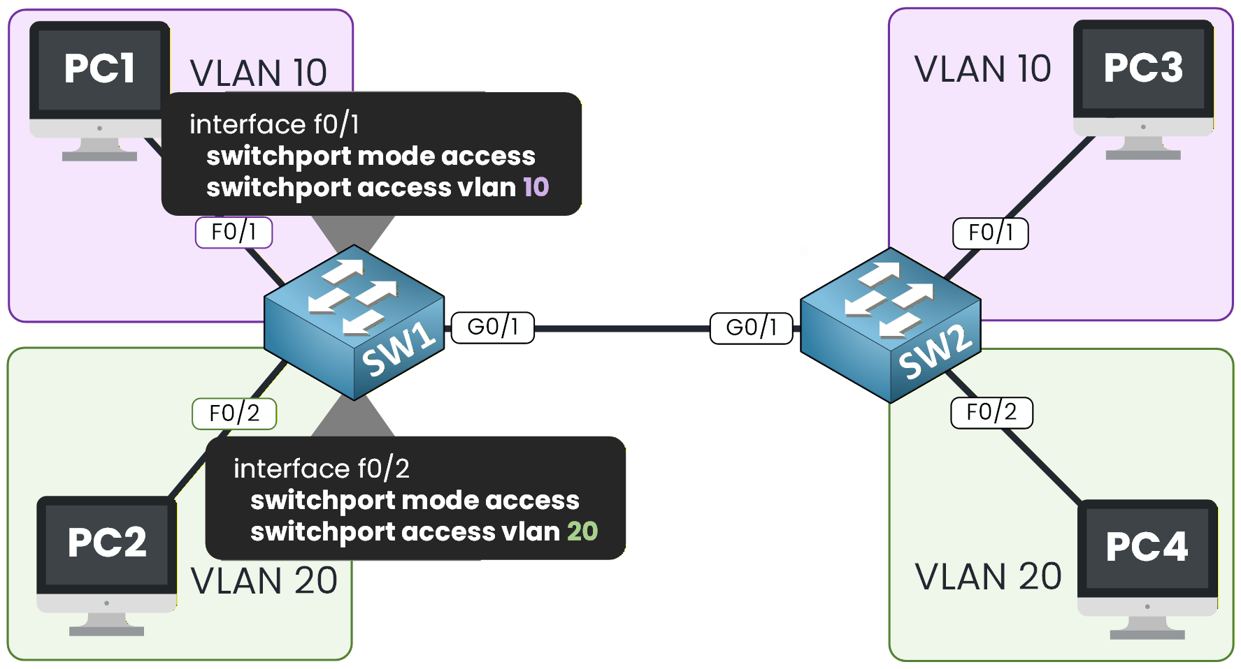
Figure 3 – VLAN Access on SW1
Take a look at Figure 3 to see how the access VLAN configuration should look.
SW1# conf t
Enter configuration commands, one per line.  End with CNTL/Z.
SW1(config)# int f0/1
SW1(config-if)# switchport mode access
SW1(config-if)# switchport access vlan 10
SW1(config-if)# exit

SW1(config)# int f0/2
SW1(config-if)# switchport mode access
SW1(config-if)# switchport access vlan 20
SW1(config-if)# end
Verify the VLAN Assignment
We can verify this again using:
SW1# show vlan brief

VLAN Name                             Status    Ports
---- -------------------------------- --------- -------------------------------
1    default                          active    Fa0/3, Fa0/4, Fa0/5, Fa0/6
                                                Fa0/7, Fa0/8, Fa0/9, Fa0/10
                                                Fa0/11, Fa0/12, Fa0/13, Fa0/14
                                                Fa0/15, Fa0/16, Fa0/17, Fa0/18
                                                Fa0/19, Fa0/20, Fa0/21, Fa0/22
                                                Fa0/23, Fa0/24, Gig0/1, Gig0/2
10   Sales                            active    Fa0/1
20   Tech                             active    Fa0/2
1002 fddi-default                     active
1003 token-ring-default               active
1004 fddinet-default                  active
1005 trnet-default                    active
Perfect, the PCs are now assigned to the correct VLANs.
We need to do the same on SW2 before moving on to the 802.1Q configuration.Answer the question below
Which command assigns interface Fa0/1 to VLAN 10?
Now let’s do the exact same configuration on SW2.
Just like before, we need to create VLAN 10 and VLAN 20, then assign the correct interfaces to each VLAN.Create VLAN 10 and VLAN 20
SW2# conf t
Enter configuration commands, one per line.  End with CNTL/Z.
SW2(config)# vlan 10
SW2(config-vlan)# name Sales
SW2(config-vlan)# exit

SW2(config)# vlan 20
SW2(config-vlan)# name Tech
SW2(config-vlan)# exit
At this point, both VLANs exist on the switch but have no ports assigned to them yet.
Assign Ports to the Correct VLANs
According to Figure 4, we can see that PC3 is in VLAN 10, and PC4 is in VLAN 20. So we need to make sure we apply the VLAN to the correct interface.
The appropriate commands are shown below.
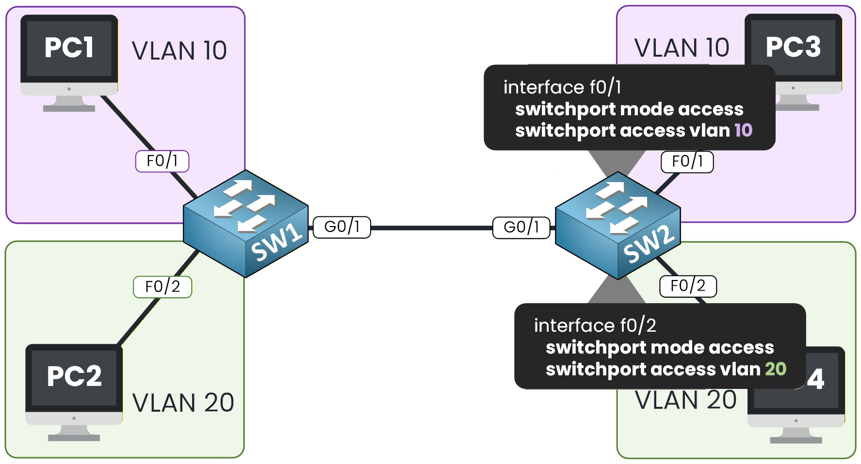
Figure 4 – VLAN Access on SW2
Let's do that on SW2.
SW2(config)# int f0/1
SW2(config-if)# switchport mode access
SW2(config-if)# switchport access vlan 10
SW2(config-if)# exit

SW2(config)# int f0/2
SW2(config-if)# switchport mode access
SW2(config-if)# switchport access vlan 20
SW2(config-if)# end
Verify the VLAN Assignment
We need to verify the VLAN association:
SW2# show vlan brief

VLAN Name                             Status    Ports
---- -------------------------------- --------- -------------------------------
1    default                          active    Fa0/3, Fa0/4, Fa0/5, Fa0/6
                                                Fa0/7, Fa0/8, Fa0/9, Fa0/10
                                                Fa0/11, Fa0/12, Fa0/13, Fa0/14
                                                Fa0/15, Fa0/16, Fa0/17, Fa0/18
                                                Fa0/19, Fa0/20, Fa0/21, Fa0/22
                                                Fa0/23, Fa0/24, Gig0/1, Gig0/2
10   Sales                            active    Fa0/1
20   Tech                             active    Fa0/2
1002 fddi-default                     active
1003 token-ring-default               active
1004 fddinet-default                  active
1005 trnet-default                    active
It's all good now, let's focus on the 802.1Q Trunking configuration together.
Answer the question below
Which command displays the VLANs configured on SW2?
Let's now configure the 802.1Q trunk link between SW1 and SW2.
This trunk is essential because it allows VLAN 10 and VLAN 20 traffic to move across both switches.
In Figure 5, the purple and green lines represent the VLANs that will be carried on the trunk once we enable it.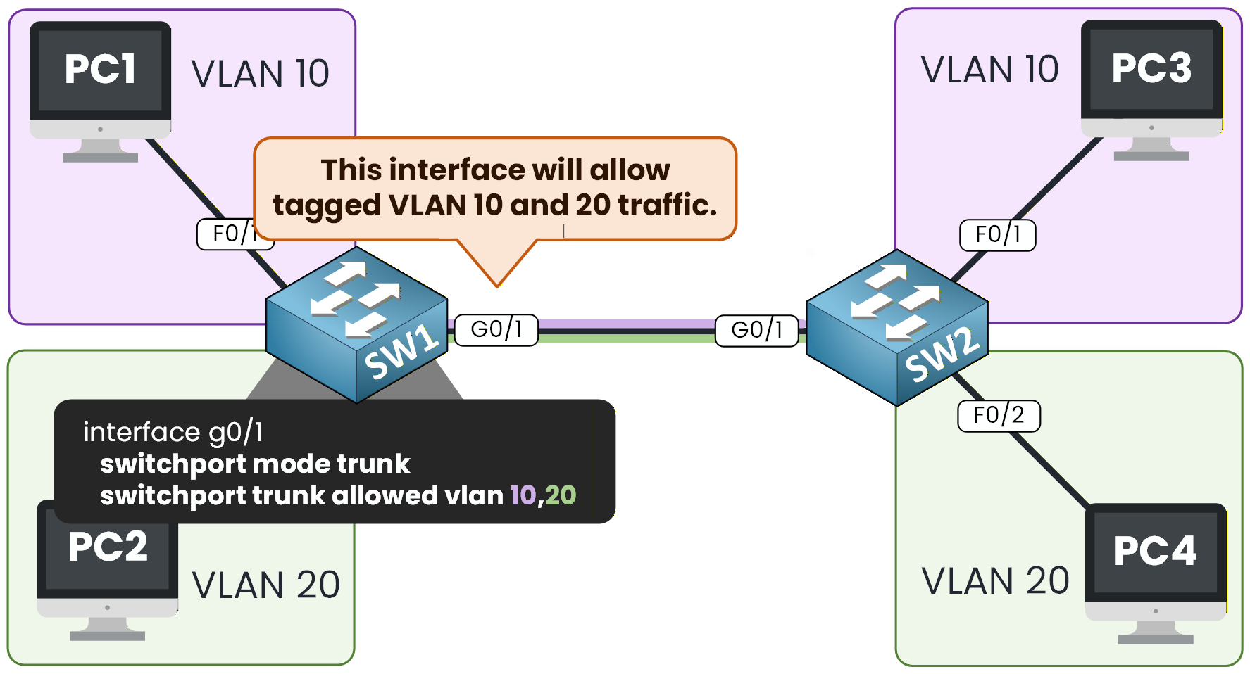
Figure 5 – Trunk Configuration on SW1
Configure the Trunk on SW1
We will start by configuring trunking on SW1.
The commands shown in Figure 5 are exactly what we need to apply.From global configuration mode, we select interface
G0/1and enable trunking:SW1# conf t Enter configuration commands, one per line. End with CNTL/Z. SW1(config)# int g0/1 SW1(config-if)# switchport mode trunk %LINEPROTO-5-UPDOWN: Line protocol on Interface GigabitEthernet0/1, changed state to down %LINEPROTO-5-UPDOWN: Line protocol on Interface GigabitEthernet0/1, changed state to upThe interface briefly goes down and comes back up once trunk mode is activated.
Now that trunking is enabled, we can specify which VLANs must be allowed on this link.
Let’s first look at the available command options:SW1(config-if)# switchport trunk ? allowed Set allowed VLAN characteristics when interface is in trunking mode native Set trunking native characteristics when interface is in trunking mode SW1(config-if)# switchport trunk allowed ? vlan Set allowed VLANs when interface is in trunking mode SW1(config-if)# switchport trunk allowed vlan ? WORD VLAN IDs of the allowed VLANs when this port is in trunking mode add add VLANs to the current list all all VLANs except all VLANs except the following none no VLANs remove remove VLANs from the current listIn our lab, we only need VLAN 10 and VLAN 20, so we apply:
SW1(config-if)# switchport trunk allowed vlan 10,20
SW1(config-if)# end
We simply separate the VLAN numbers with a comma.
Verify the Trunk Configuration on SW1
Now let’s check that both VLANs are allowed on the trunk:
SW1# show interface trunk
Port        Mode         Encapsulation  Status        Native vlan
Gig0/1      on           802.1q         trunking      1

Port        Vlans allowed on trunk
Gig0/1      10,20

Port        Vlans allowed and active in management domain
Gig0/1      10,20

Port        Vlans in spanning tree forwarding state and not pruned
Gig0/1      10,20
On Vlans allowed on trunk, we clearly see VLAN 10 and VLAN 20.
This confirms that the trunk is correctly configured on SW1.You can also see that the Native VLAN is 1. This is the default value, and we will study it in detail in a later lesson.
To make the trunk link operational, we now need to apply the same configuration on the other side of the link, on SW2.
Configure the Trunk on SW2
On SW2, we use the exact same commands.
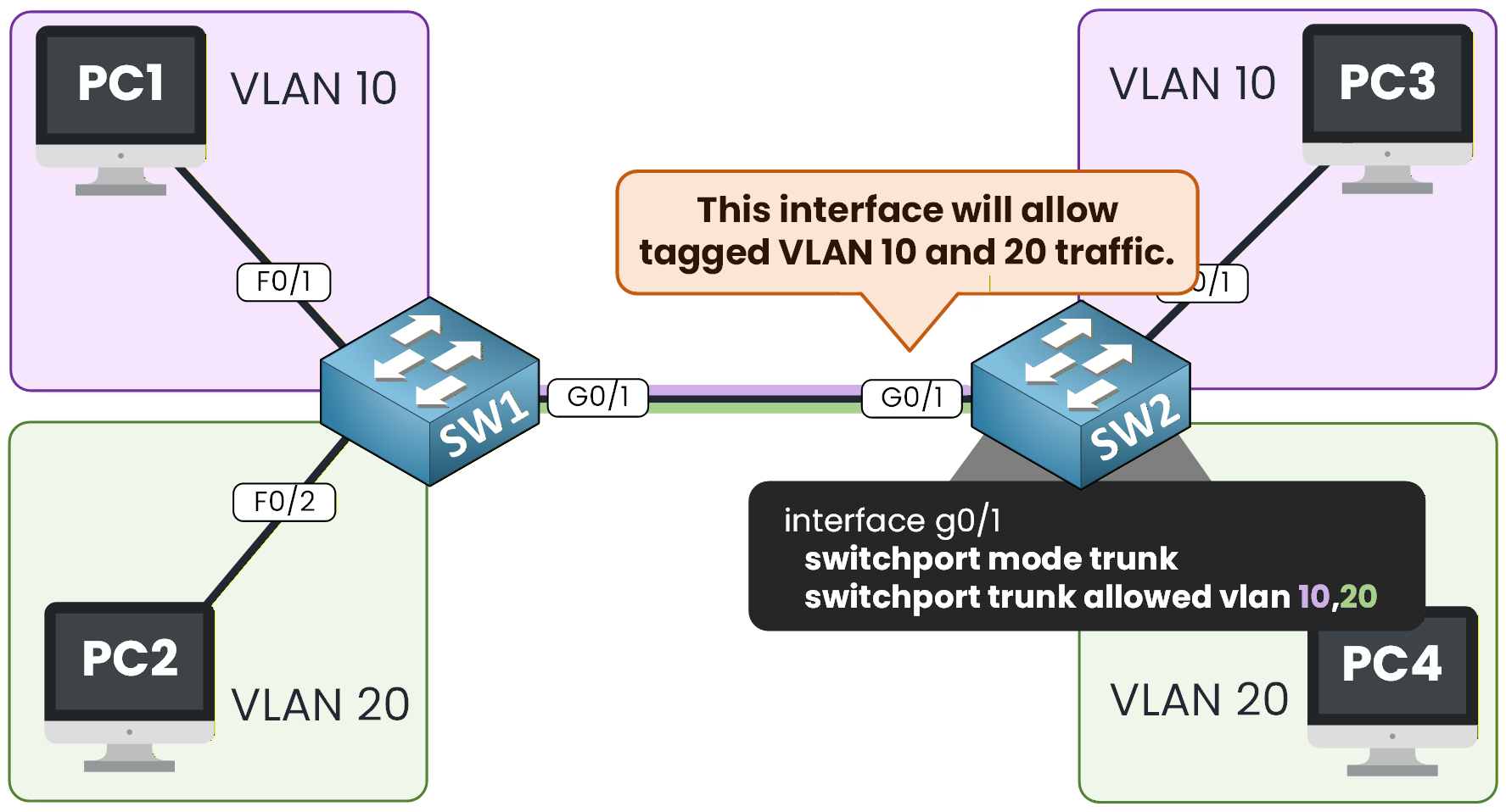
Figure 6 – Trunk Configuration on SW2
SW2(config)# int g0/1
SW2(config-if)# switchport mode trunk
SW2(config-if)# switchport trunk allowed vlan 10,20
SW2(config-if)# end
Verify the Trunk on SW2
Once the configuration is applied, we verify that VLAN 10 and VLAN 20 are allowed on the trunk:
SW2# show interfaces trunk
Port        Mode         Encapsulation  Status        Native vlan
Gig0/1      on           802.1q         trunking      1

Port        Vlans allowed on trunk
Gig0/1      10,20

Port        Vlans allowed and active in management domain
Gig0/1      10,20

Port        Vlans in spanning tree forwarding state and not pruned
Gig0/1      10,20
At this point, both sides of the trunk are configured and the link is fully functional.
Adding a VLAN to an Existing Trunk
In production, trunk links often already carry several VLANs. If VLAN 10 and VLAN 20 are currently allowed and you need to add VLAN 30, you can simply add it to the existing list instead of replacing it.
SW1(config)# int g0/1
SW1(config-if)# switchport trunk allowed vlan add 30
This command adds VLAN 30 to the allowed VLANs without removing the others, and you will encounter it frequently in real environments.
In our lab, we will not apply this command because we want to test communication only for VLAN 10 and VLAN 20. But keep it in mind, as it is very common in production networks.
Now that you are familiar with this behavior, you can verify that VLAN 10 and VLAN 20 work correctly across the trunk. Make sure both switches are configured as trunk ports, then verify that devices in the same VLAN can communicate.
Answer the question below
What command allows only VLAN 10 and VLAN 20 on the trunk link?
We will start with VLAN 10, then test VLAN 20, and confirm that the tagged traffic is correctly forwarded between SW1 and SW2.
PC1 to PC3 (VLAN 10 Communication)
Let’s begin by testing connectivity between PC1 (VLAN 10) on SW1 and PC3 (VLAN 10) on SW2.
C:\> ping 10.0.1.3

Pinging 10.0.1.3 with 32 bytes of data:

Reply from 10.0.1.3: bytes=32 time<1ms TTL=128
Reply from 10.0.1.3: bytes=32 time<1ms TTL=128
Reply from 10.0.1.3: bytes=32 time<1ms TTL=128
Reply from 10.0.1.3: bytes=32 time<1ms TTL=128

Ping statistics for 10.0.1.3:
    Packets: Sent = 4, Received = 4, Lost = 0 (0% loss),
Approximate round trip times in milli-seconds:
    Minimum = 0ms, Maximum = 0ms, Average = 0ms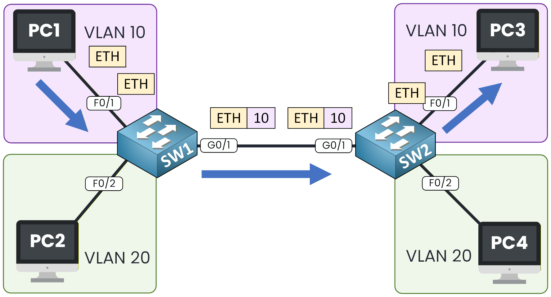
Figure 7 – VLAN 10 Tagged Traffic Flow
The ping works perfectly, meaning VLAN 10 traffic is correctly tagged on SW1, carried over the trunk, and received by SW2.
PC2 to PC4 (VLAN 20 Communication)
Now let’s do the same test for VLAN 20, between PC2 and PC4, which are also located on different switches.
C:\> ping 10.0.2.4

Pinging 10.0.2.4 with 32 bytes of data:

Reply from 10.0.2.4: bytes=32 time<1ms TTL=128
Reply from 10.0.2.4: bytes=32 time<1ms TTL=128
Reply from 10.0.2.4: bytes=32 time<1ms TTL=128
Reply from 10.0.2.4: bytes=32 time<1ms TTL=128

Ping statistics for 10.0.2.4:
    Packets: Sent = 4, Received = 4, Lost = 0 (0% loss),
Approximate round trip times in milli-seconds:
    Minimum = 0ms, Maximum = 0ms, Average = 0ms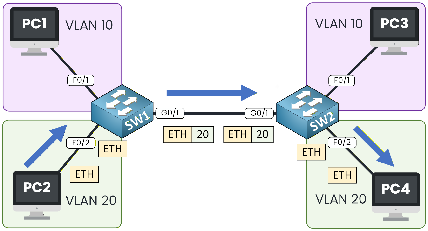
Figure 8 – VLAN 20 Tagged Traffic Flow
Again, the communication is successful.
This confirms that VLAN 20 traffic is properly tagged and forwarded across the 802.1Q trunk.Answer the question below
True or False: On an 802.1Q trunk, the switch knows a frame's VLAN from a tag inserted into the frame.
Congratulations, you have completed the 802.1Q Trunking Lab!
This lab is an essential step in your CCNA learning path, because trunking is at the core of how VLANs extend across multiple switches in real networks.You now understand how to create VLANs, assign access ports, activate an 802.1Q trunk, and verify that tagged VLAN traffic flows correctly between switches.
Below, you will find the main commands used in this lab and their meaning.
Useful Commands to Remember
switchport mode access
⇒ Forces the port to operate as an access port.switchport access vlan 10
⇒ Assigns the port to VLAN 10.switchport mode trunk
⇒ Enables 802.1Q trunking on the interface.switchport trunk allowed vlan 10,20
⇒ Allows VLAN 10 and VLAN 20 on the trunk link.switchport trunk allowed vlan add 30
⇒ Adds VLAN 30 to the existing allowed VLAN list without removing the previous VLANs.show vlan brief
⇒ Displays all VLANs and their associated ports.show interfaces trunk
⇒ Shows the trunk status and which VLANs are allowed and active.You've seen every command needed to bring a trunk up. Let's continue with the 802.1Q Trunking lab, where you'll configure the trunk and confirm that VLAN traffic crosses it.
Answer the question below
How do you add VLAN 99 to a trunk link that already allows VLANs?