CIDR (Classless Inter-Domain Routing) is a method introduced in 1993 by the IETF to improve IPv4 address allocation and reduce address waste.
Before CIDR, IPv4 used a classful addressing system, where networks were limited to three fixed prefix sizes:Class A → fixed /8 prefix
Class B → fixed /16 prefix
Class C → fixed /24 prefix
This rigid structure led to significant address waste, especially when organizations received far more addresses than needed.
In 1985, subnetting was introduced, allowing Class A, B, and C networks to be divided into smaller segments.
For example, a Class A network could be split into Class B– or Class C–sized blocks.To visualize this evolution, look at Figure 1 below.
It shows how IPv4 moved from Classes, to Subnetting, and finally to CIDR.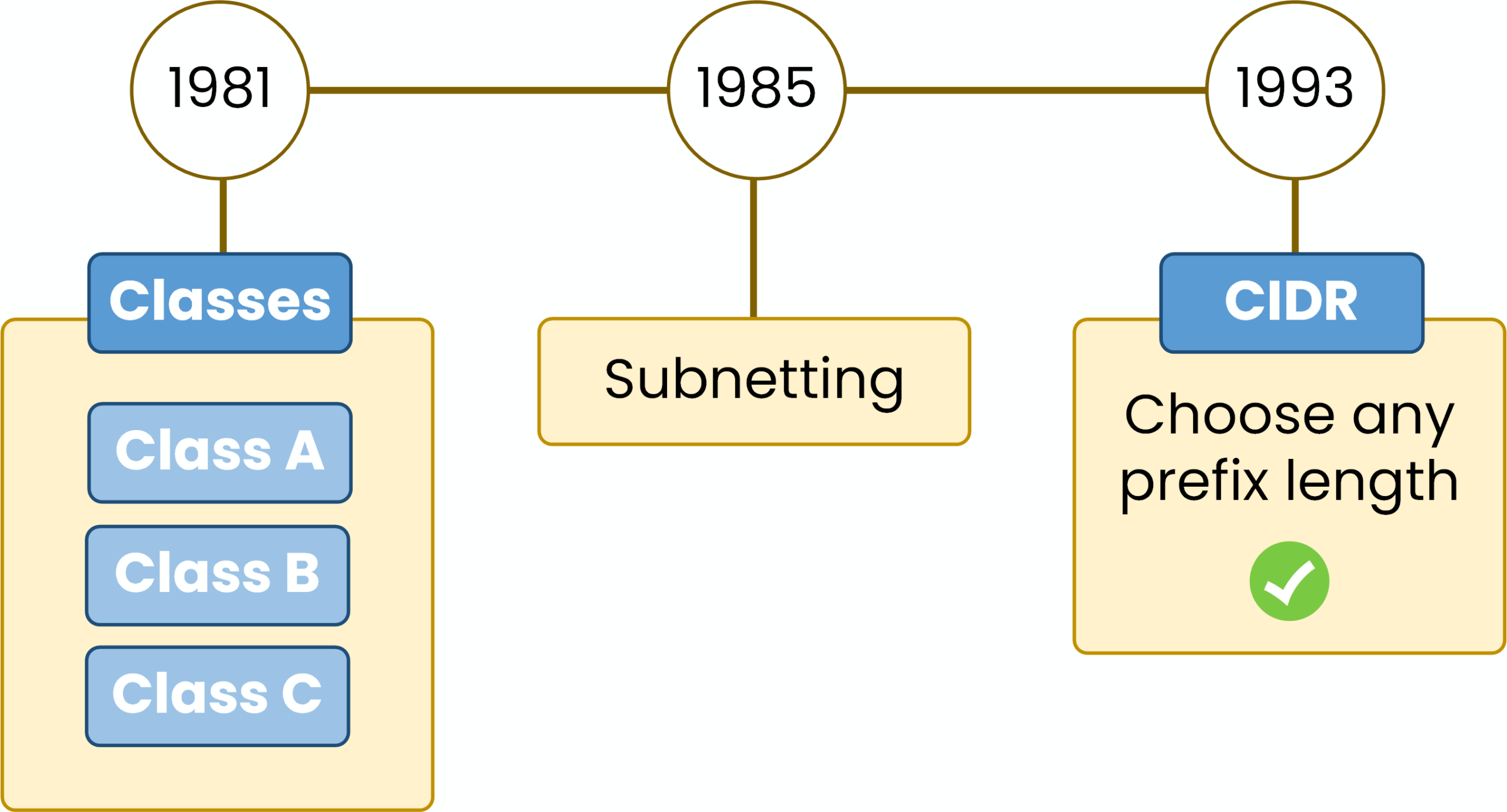
Figure 1 – IPv4 evolution: classes, subnetting, CIDR.
Even with subnetting, one limitation remained:
you still couldn’t choose any prefix length. Networks were always tied to /8, /16, or /24 based on their original class.CIDR removed these restrictions in 1993 by eliminating address classes entirely.
From that point on, networks could use any prefix length such as /20, /21, /27, or /30 making IPv4 addressing far more flexible and efficient.Answer the question below
What does CIDR mean?
The prefix length is the number that appears after the slash in an IPv4 address, such as /24 in 198.51.100.0/24.
It tells you how many bits are used for the network portion of the address.The remaining bits form the host portion, which identifies devices inside the network.
Examples:
/24→ 24 network bits, 8 host bits/25→ 25 network bits, 7 host bits/30→ 30 network bits, 2 host bits
The prefix length also maps directly to the subnet mask:
/24= 255.255.255.0/25= 255.255.255.128/26= 255.255.255.192
CIDR uses this notation because it lets you create networks of any size, instead of being limited by class-based boundaries.
Answer the question below
What does the prefix length indicate?
Every IPv4 address is divided into two logical parts:
Network portion → identifies the network
Host portion → identifies devices inside that network
The prefix length defines exactly where this separation occurs.
For example, in 198.51.100.0/24:
The first 24 bits are the network portion
The remaining 8 bits are the host portion
You can see this division clearly in the diagram below.
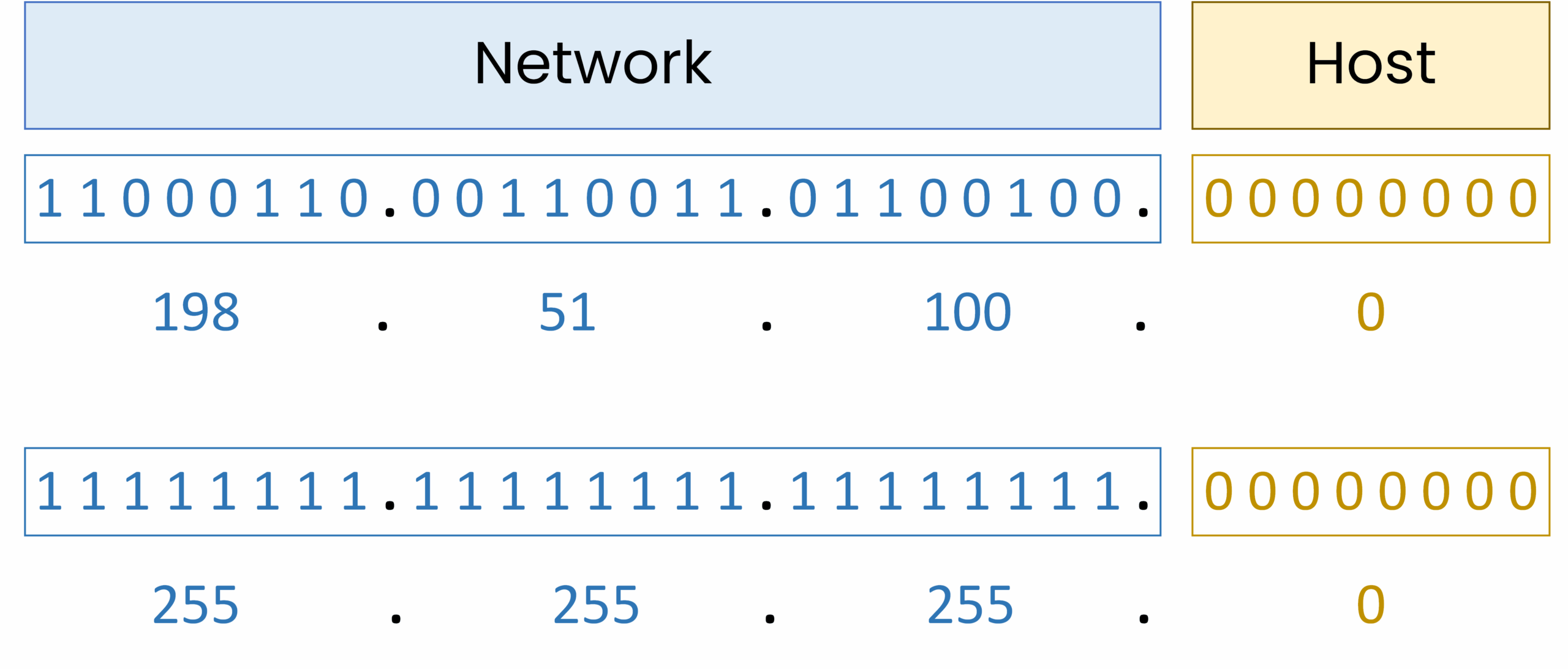
Figure 2 – IPv4 198.51.100.0/24 with subnet mask, showing network and host bits.
All devices in this network share the same first 24 bits.
Only the host bits change to create unique IP addresses.This separation is essential because CIDR works by adjusting how many bits belong to the network and how many remain for hosts.
Answer the question below
In a /24 network, how many bits are used for hosts?
Viewing Network and Host Portions in Cisco IOS
Now let’s see how a router interprets this separation in practice.
We configure an interface with a /24 subnet:Router# conf t Enter configuration commands, one per line. End with CNTL/Z. Router(config)# interface g0/0 Router(config-if)# ip address 198.51.100.1 255.255.255.0 Router(config-if)# no shutdown Router(config-if)# end %SYS-5-CONFIG_I: Configured from console by consoleNow verify the configuration:
Router# show ip interface g0/0
GigabitEthernet0/0 is up, line protocol is up
  Internet address is 198.51.100.1/24
Notice something important:
Even though we entered the subnet mask as 255.255.255.0,
the router displays the address using CIDR notation (/24).This confirms that:
The first 24 bits represent the network portion
The remaining 8 bits represent the host portion
Cisco IOS internally works using prefix length notation
Answer the question below
CIDR gives you full control over the size of your networks by letting you adjust the prefix length.
When you increase the prefix length (for example from /24 to /25 or /26):More bits are used for the network portion
Fewer bits remain for hosts
You create more subnets
Each subnet supports fewer devices
This flexibility is what makes CIDR far more efficient than the old classful system.
CIDR also lets you calculate exactly how many usable hosts each subnet can provide.
Use the formula below: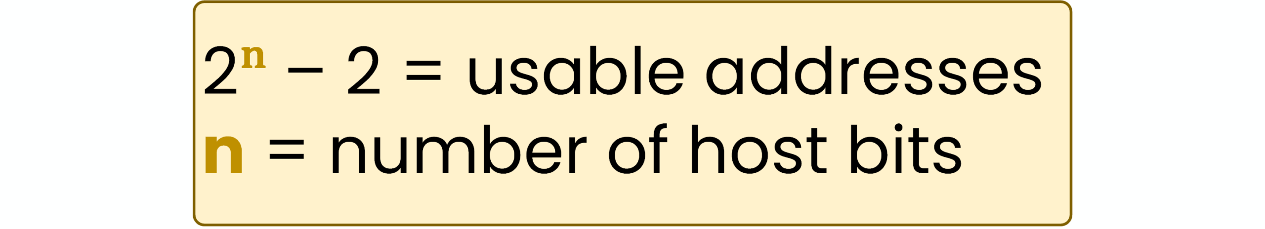
Figure 3– Formula for usable IP addresses.
Where:
n = number of host bits = (32 − prefix length)
The subtraction of 2 removes the network and broadcast addresses
This calculation helps you choose a subnet size that fits your requirements without wasting address space.
Answer the question below
If a /24 network becomes a /25, how many bits are used for the network portion?
Let’s apply the formula to the network
198.51.100.0/24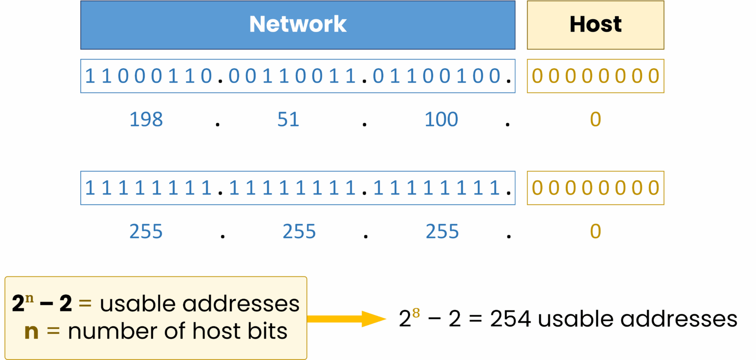
Figure 4 – Calculating usable addresses with a /24 subnet mask.
The prefix length is /24.
So:n = 32 − 24 = 8 host bits
2⁸ − 2 = 254 usable hosts
Now let’s see how increasing the prefix length (/25, /26, /27…) changes the number of usable addresses.
40 % Complete: you’re making great progress
Unlock the rest of this lesson
If you’d like to continue your CCNA journey, simply create your free account.
Access all CCNA lessons
Practice with hands-on labs
Train with Practice exams and Quizzes
Progress tracking in your dashboard
Made by network engineers - CCNP certified
learners globally
CIDR (Classless Inter-Domain Routing)
CIDR lets you size IPv4 networks precisely by choosing the right prefix length instead of wasting addresses with fixed classes. In this lesson you will plan subnets step by step and validate usable hosts with confidence.