SVI InterVLAN Routing

1. SVI InterVLAN Routing with Layer 3 Switches

SVI InterVLAN Routing is a method that allows Layer 3 switches to route traffic between VLANs without relying on an external router. By combining switching and routing capabilities within a single device, Layer 3 switches provide a faster, more scalable solution for network communication.

This type of SVI InterVLAN Routing setup is essential for networks that require efficient VLAN communication without external routing devices.

The diagram below illustrates a typical topology for implementing SVI InterVLAN Routing with a Layer 3 switch:
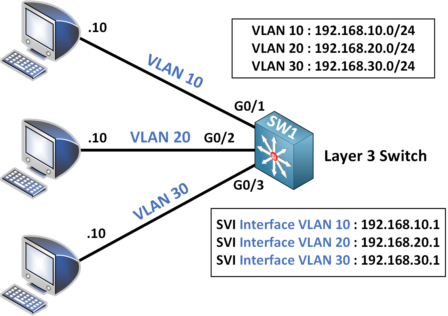
SVI InterVLAN Routing topology showing how a Layer 3 switch connects VLANs using Switch Virtual Interfaces (SVIs).

Key Topology Overview

In this setup we see differents things :

  • A SW1 (Layer 3 Switch) is connected to PCs in different VLANs (VLAN 10, VLAN 20, and VLAN 30).
  • Each VLAN is assigned an SVI (Switch Virtual Interface) to act as its gateway for Inter-VLAN Routing.

2. Configuring SVIs (Switch Virtual Interfaces)

Step 1: Create VLANs on SW1

Define each VLAN on SW1 with a unique VLAN ID:

SW1(config)# vlan 10
SW1(config-vlan)# name Sales

SW1(config)# vlan 20
SW1(config-vlan)# name Engineering

SW1(config)# vlan 30
SW1(config-vlan)# name Accounting

Step 2: Configure SVIs for Each VLAN

An SVI serves as the default gateway for devices in each VLAN. Here we need to configure an IP address for each SVI that aligns with the respective VLAN’s subnet !

  • SVI for VLAN 10:
SW1(config)# interface vlan 10
SW1(config-if)# ip address 192.168.10.1 255.255.255.0
SW1(config-if)# no shutdown
  • SVI for VLAN 20:
SW1(config)# interface vlan 20
SW1(config-if)# ip address 192.168.20.1 255.255.255.0
SW1(config-if)# no shutdown
  • SVI for VLAN 30:
SW1(config)# interface vlan 30
SW1(config-if)# ip address 192.168.30.1 255.255.255.0
SW1(config-if)# no shutdown

Step 3: Assign Access Ports to VLANs

Assign each port connected to a PC to its respective VLAN.

  • Assign G0/1 to VLAN 10:
SW1(config)# interface GigabitEthernet0/1
SW1(config-if)# switchport mode access
SW1(config-if)# switchport access vlan 10
  • Assign G0/2 to VLAN 20:
SW1(config)# interface GigabitEthernet0/2
SW1(config-if)# switchport mode access
SW1(config-if)# switchport access vlan 20
  • Assign G0/3 to VLAN 30:
SW1(config)# interface GigabitEthernet0/3
SW1(config-if)# switchport mode access
SW1(config-if)# switchport access vlan 30

3. Verification

To verify the functionality of SVI InterVLAN Routing, we are conducting a ping test… from a PC in VLAN 10 (IP address 192.168.10.10) to a PC in VLAN 30 (IP address 192.168.30.10). This test will confirm whether devices in different VLANs can communicate with each other through the configured Layer 3 switch, ensuring proper routing across VLANs.

SVI InterVLAN Routing verification by testing communication between different VLANs on a Layer 3 switch.
PC1> ping 192.168.30.10

Pinging 192.168.30.10 with 32 bytes of data:

Reply from 192.168.30.10: bytes=32 time<1ms TTL=64

Ping statistics for 192.168.30.10:
    Packets: Sent = 4, Received = 4, Lost = 0 (0% loss),
Approximate round trip times in milli-seconds:
    Minimum = <1ms, Maximum = <1ms, Average = <1ms

With this successful ping output and our configured Inter-VLAN Routing settings, we can confirm that Inter-VLAN Routing is operational, allowing communication between devices in VLAN 10 and VLAN 30 through the Layer 3 switch.